These are the assembly instructions for the DarkNet 8 Badge Kit.
This badge not only is an excellent opportunity to learn how to solder, it is also a tool that is used to communicate with other agents participating in the DarkNet contest. It can be used to pair with other agent's badges, as well as is instrumental in several of the challenges you will encounter when playing with the DarkNet.
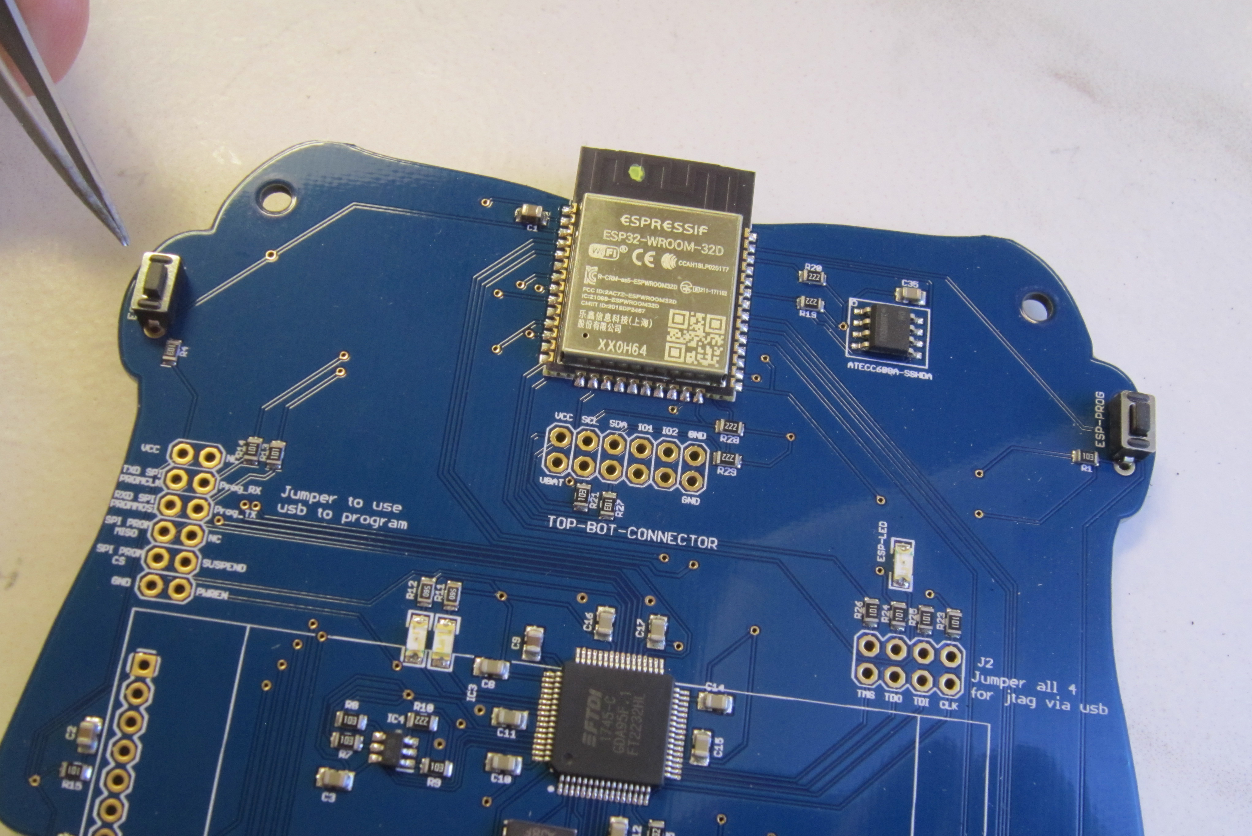
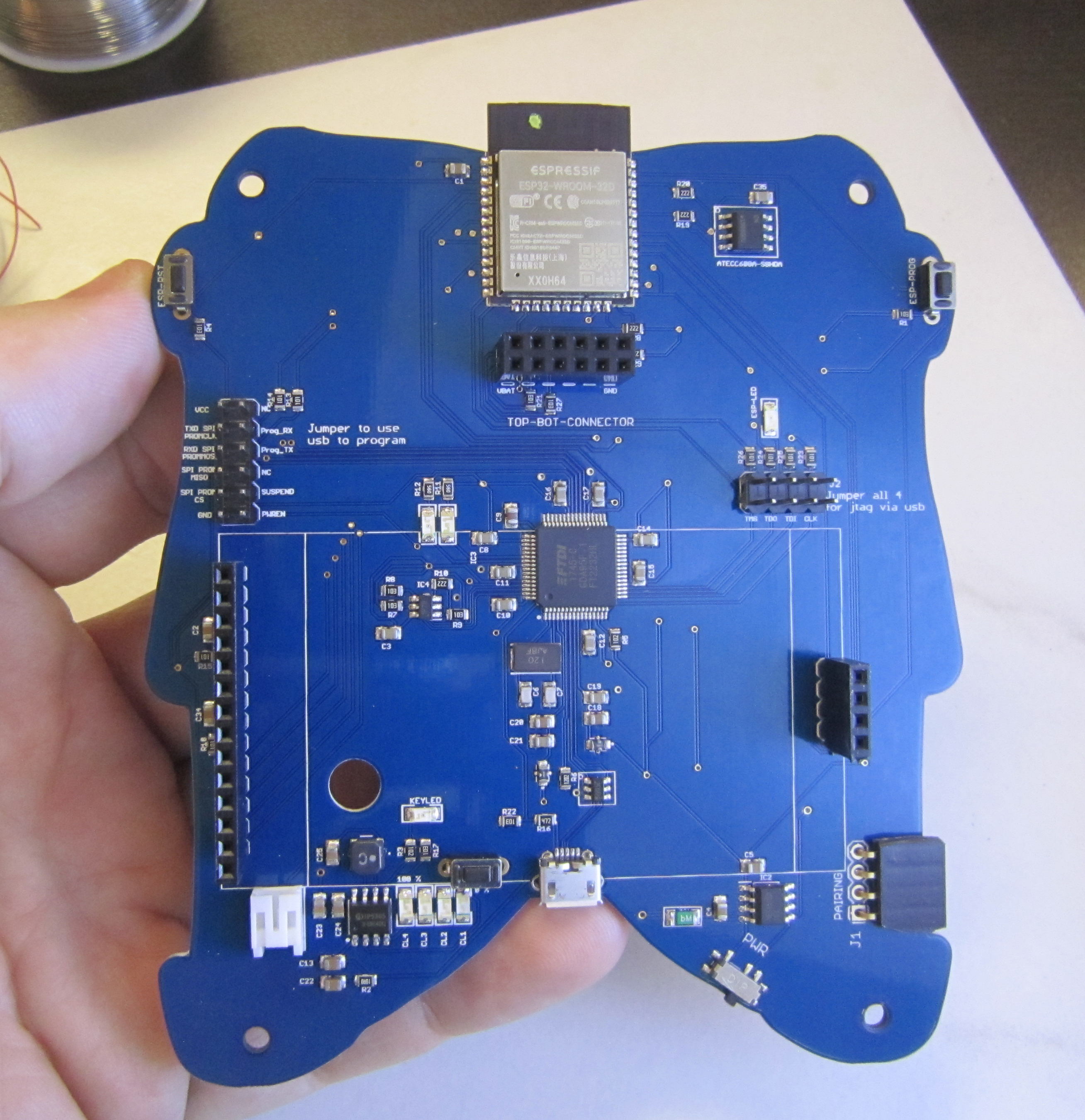
This badge was designed to be easy to solder, as well as hackable. It is based on the ESP-WROOM-32 microcontroller, and can programmed using an integrated FTDI serial debugger chip. Handling the lighting is the AVR 4809 microcontroller.
This year's badge hardware was designed by Cmdc0de, with advice help, and late night phone calls from Bunni and Krux. The firmware was developed by Cmdc0de and Gourry, with some hackery LED blinky code added by Krux. Badge look and artwork, and bottom board silk screen puzzles were done by Krux. The top board silk screen puzzle was done by Cmdc0de.
Avoid common mistakes, and read through this guide in it's entirety before beginning. The order of assembly matters for some components in this kit.
You will need the following tools to assemble this kit
- Temperature controlled soldering station
- Fine solder, 0.032" diameter or smaller
- De-soldering pump / de-soldering braid
- Flush cut wire cutters
- Pliers
- Phillips head screwdriver
- Tweezers for surface mount soldering components
- Safety glasses
- Optional: PCB vice
- Optional: Denatured alcohol to clean the board after soldering
When soldering, it is important to always follow safe work habits. Be mindful of yourself and others. The following documents address some of the safety concerns when soldering
- Soldering Safety
- Lead Soldering Safety Guidelines
- Lead-Free_Solder_Fumes_Increase_Need_for_Fume_Extraction
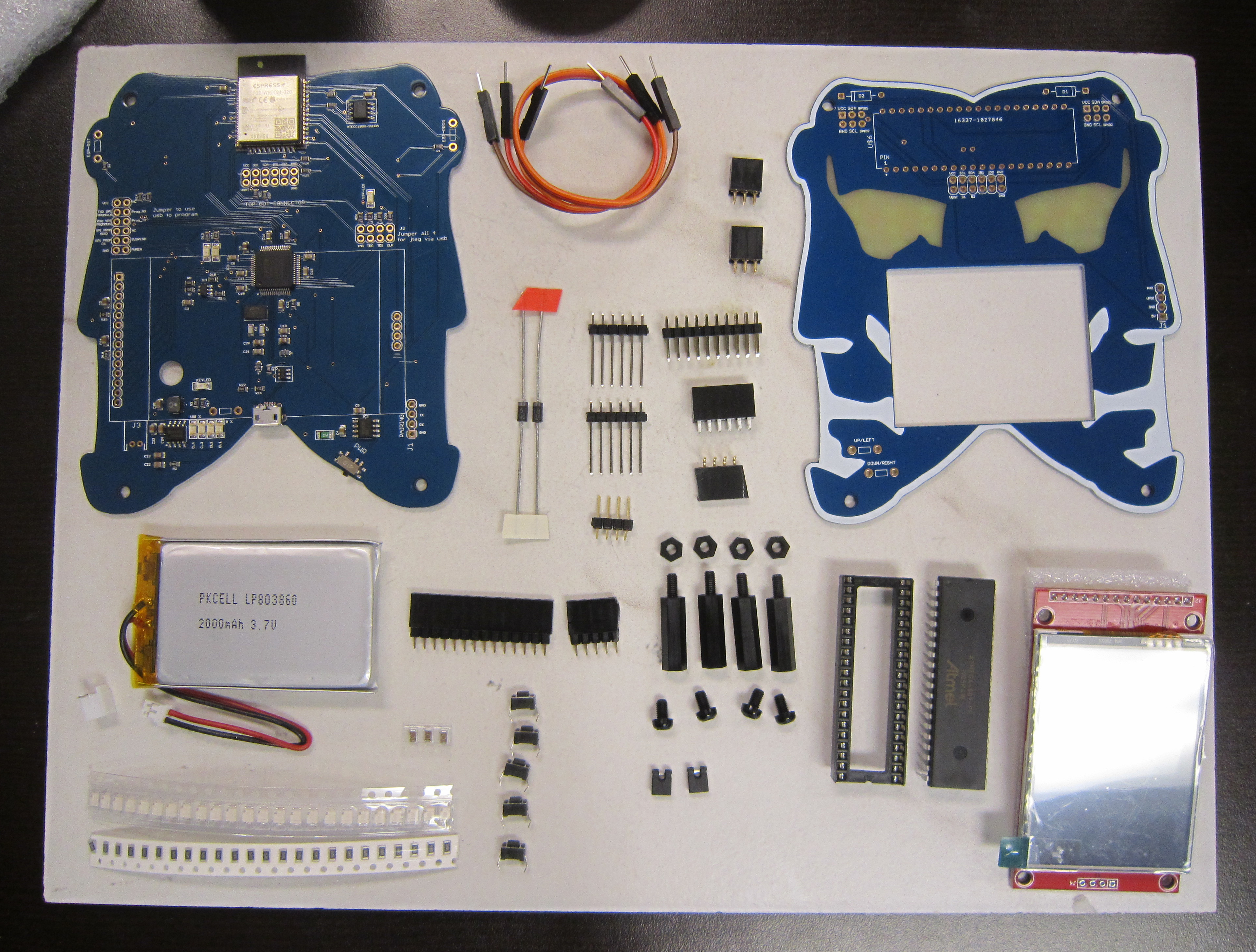
Before you get started, take a moment to ensure that all the components have been included with the kit.
Note: This is also a good time to turn on your soldering iron. For leaded solder, 320 degrees Celsius is a good working temperature.
- One Darknet Industries, Darket 8 badge top board
- One Darknet Industries, Darket 8 badge bottom board
- One 2.4" color LCD display resistive touch screen module with stylus
- One four pin male header for LCD display
- One four pin tall female header for LCD display
- One fourteen pin tall female header for LCD display
- One four pin right angle female header for badge to badge pairing
- Two tall six pin male headers for board to board communication (top board)
- one six x two female header for board to board communication (bottom board)
- One ten x two male header for programming options jumpers
- Two jumper selectors
- Two three x two female headers for SAO ports
- Three male to male jumper wires
- One fourty pin IC stocket
- One Atmel 4806 microcontroller
- Two diodes
- Three SMD capacitors
- Twentyfour SMD resistors
- Twentyfour SMD LEDs
- Five Tactile Switches
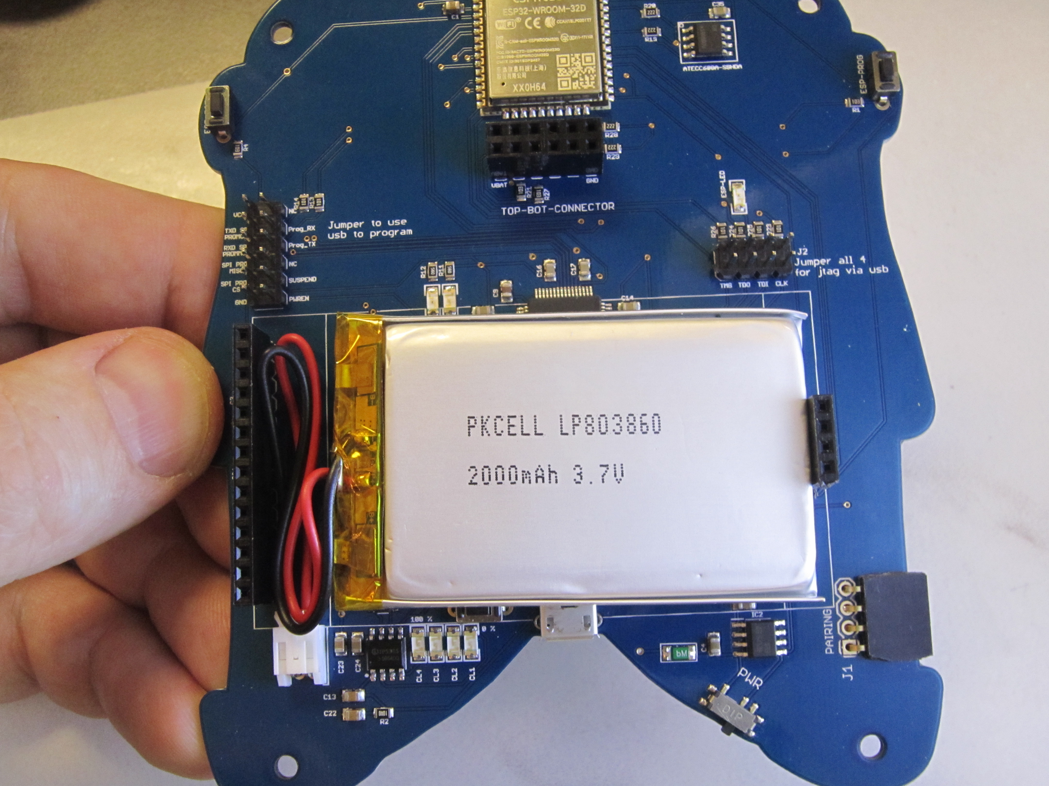
- One Lipo battery
- One JST battery connector
- Four 3mm nylon nuts
- Four 3mm nylon screws
- Four 3mm nylon washers (not pictured)
- Four nylon standoffs
- One DarkNet Lanyard
Click on any of the images for a high-resolution version.
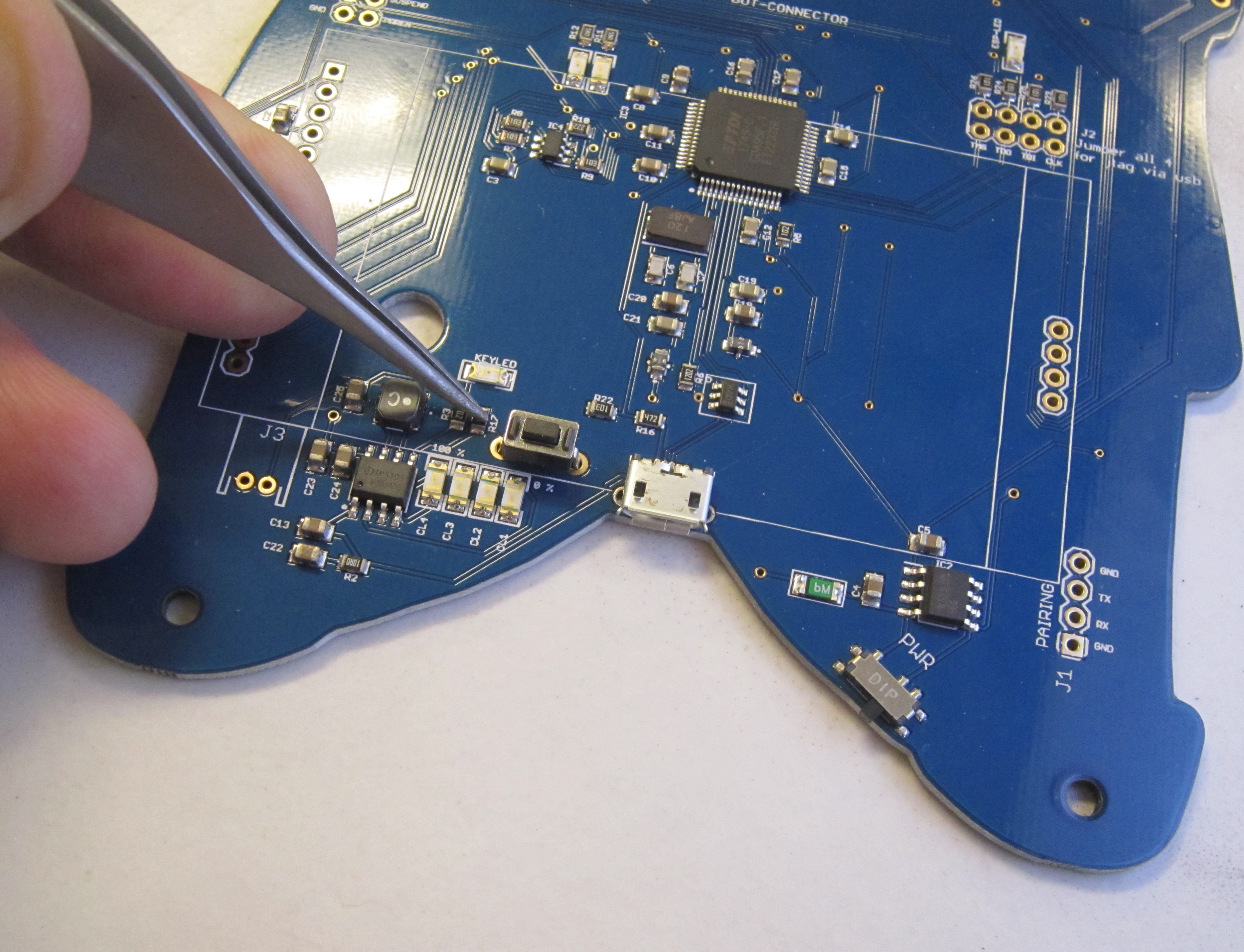
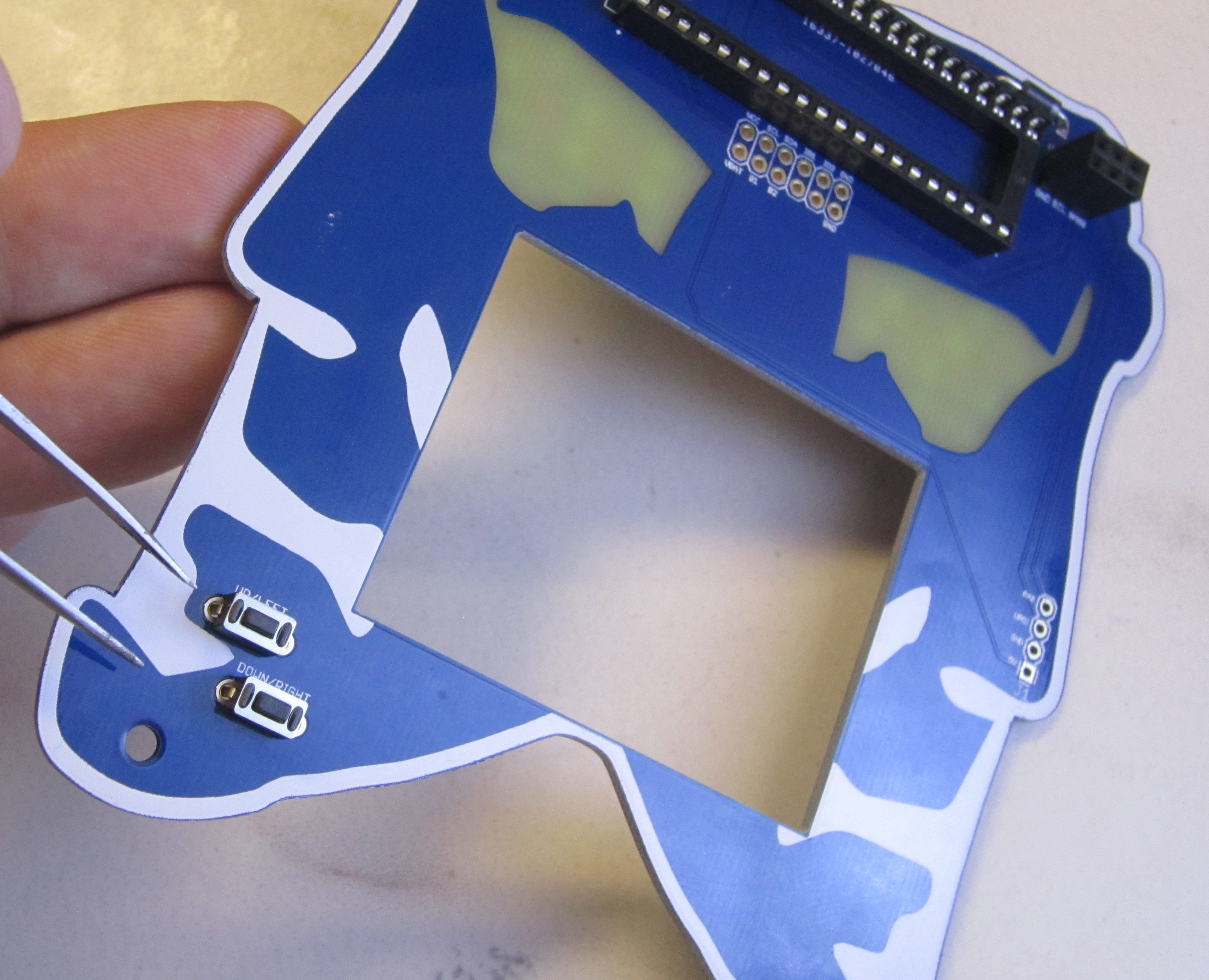
The bottom board has three momentary buttons. We'll start with the one that controls the charging circuit.
Next to the Micro USB connector is where you install the first switch. This switch is used to manually power on and off the LiPo charge circuit output. Once installed, if you tripple click the button, the LiPo charge circuit output will turn off. Under normal operation this will usually turn off automatically.
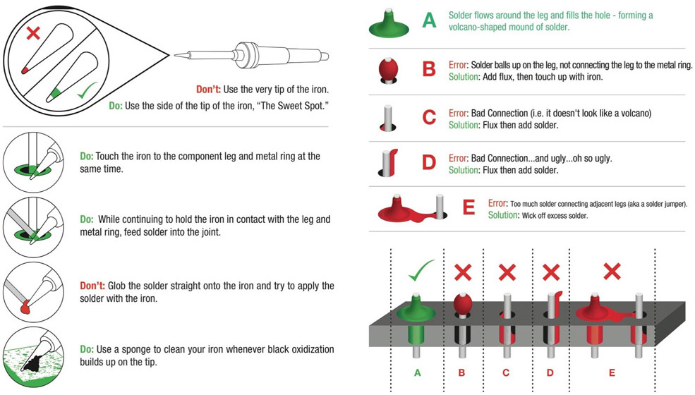
Ensure the tip of your soldering iron is always kept clean. It should be shiny in appearance. Removing the oxidation by wiping the soldering iron on a solder sponge.
When using a chisel tip as show, the flat of the tip can be used. When using a conical tip, use the section of the iron just to the side of the tip. This gives you a larger area of thermal contact and will make soldering easier.
Begin soldering by positioning the tip of the iron so that it makes firm contact with both the solder pad on the PCB and the lead of the component. This ensures that both the pad and the part both get sufficiently hot so that they are able to melt the solder and make a good electrical connection. Feed solder in sparingly on the side opposite the soldering iron. The solder should flow on the solder pad and lead of the component, forming a conical shape.
The following diagram shows more details on soldering DOs and DON'Ts
Solder the switch in place.
To aid in soldering, and to help keep the components in place, with through hole parts the leads may be splayed at a slight angle to hold the parts in place. The momentary switches usually do not require this. Though you may solder one lead, check that the part is flush with the board and then re-melt the solder while adjusting the switch position if needed. Once this is verified solder the other lead of the switch.
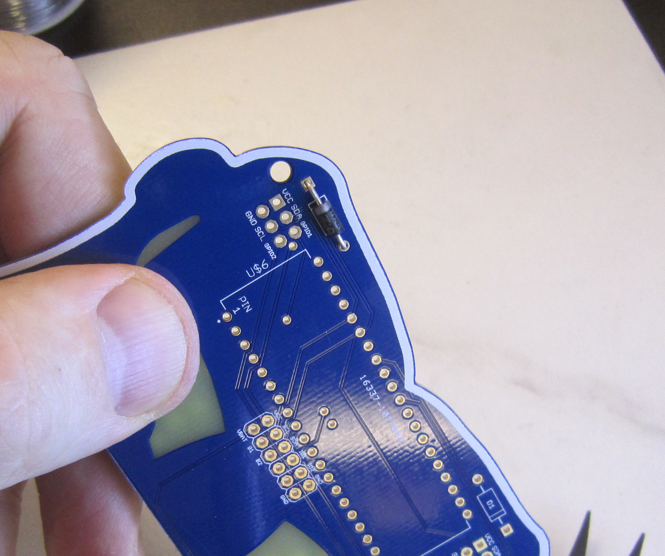
Next we'll solder the right angle pairing header. Ensure it sits flush against the PCB when soldering.
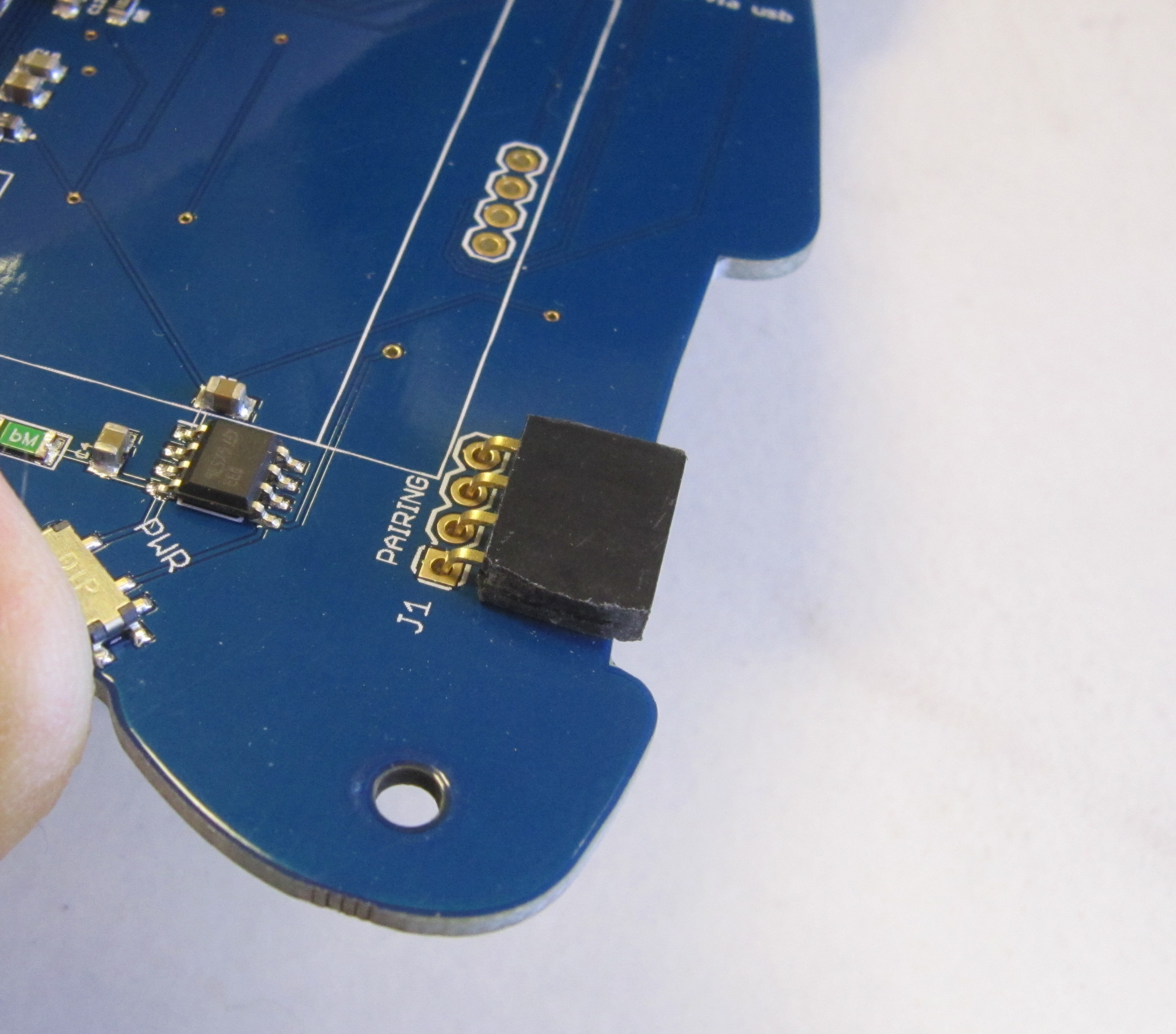
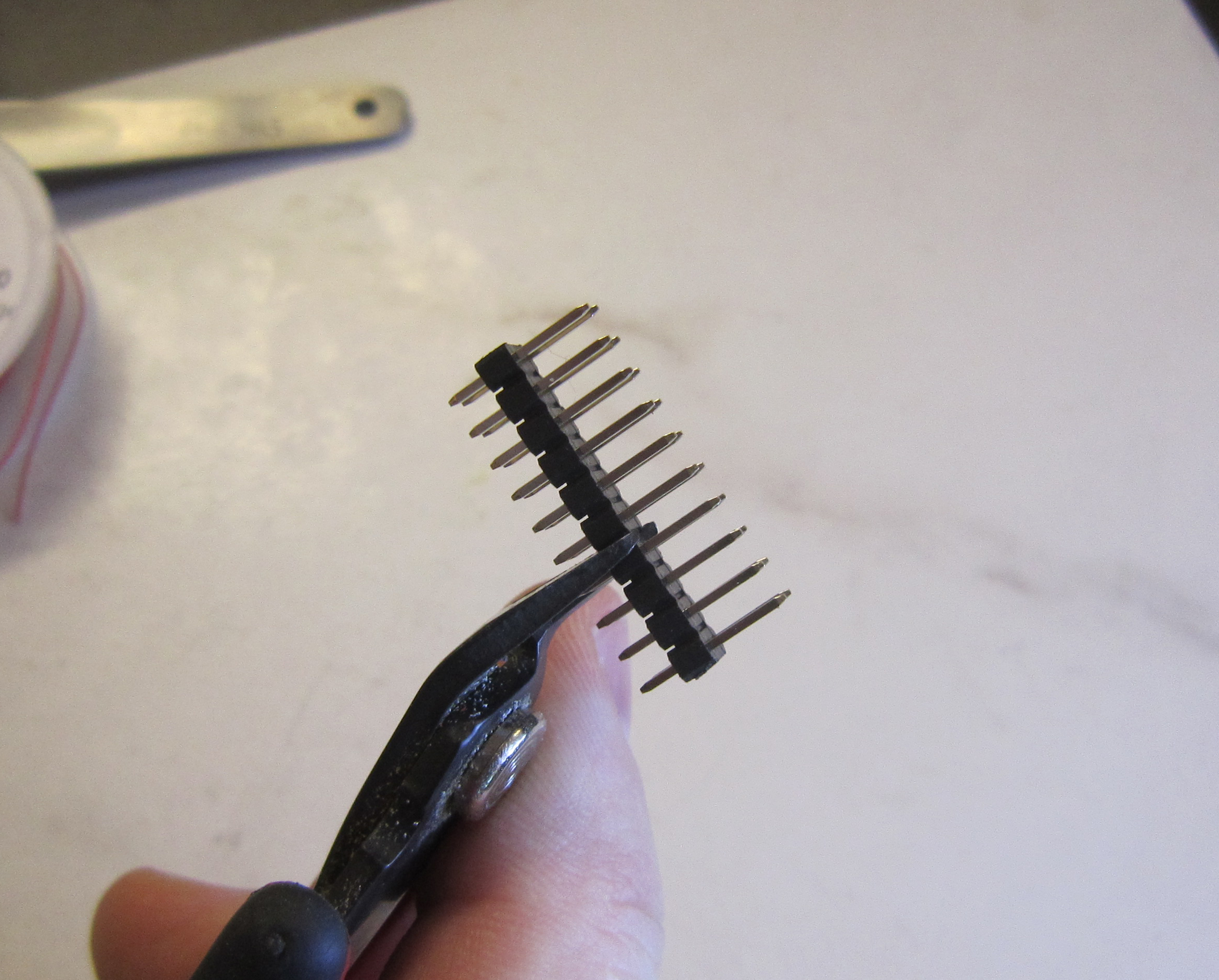
Once soldered trim the header pins using flush cutters.
Note: This is only needed for these pins. Other headers do not need to be trimmed.
Safety Tip: When cutting component leads, ensure that you are holding
the lead, or if it is too short, cover the lead when you cut the part to prevent the lead from becoming a projectile.
Not doing this can lead to eye injury for yourself or others. You can
easily do this by holding a finger tip over the lead as you cut it.
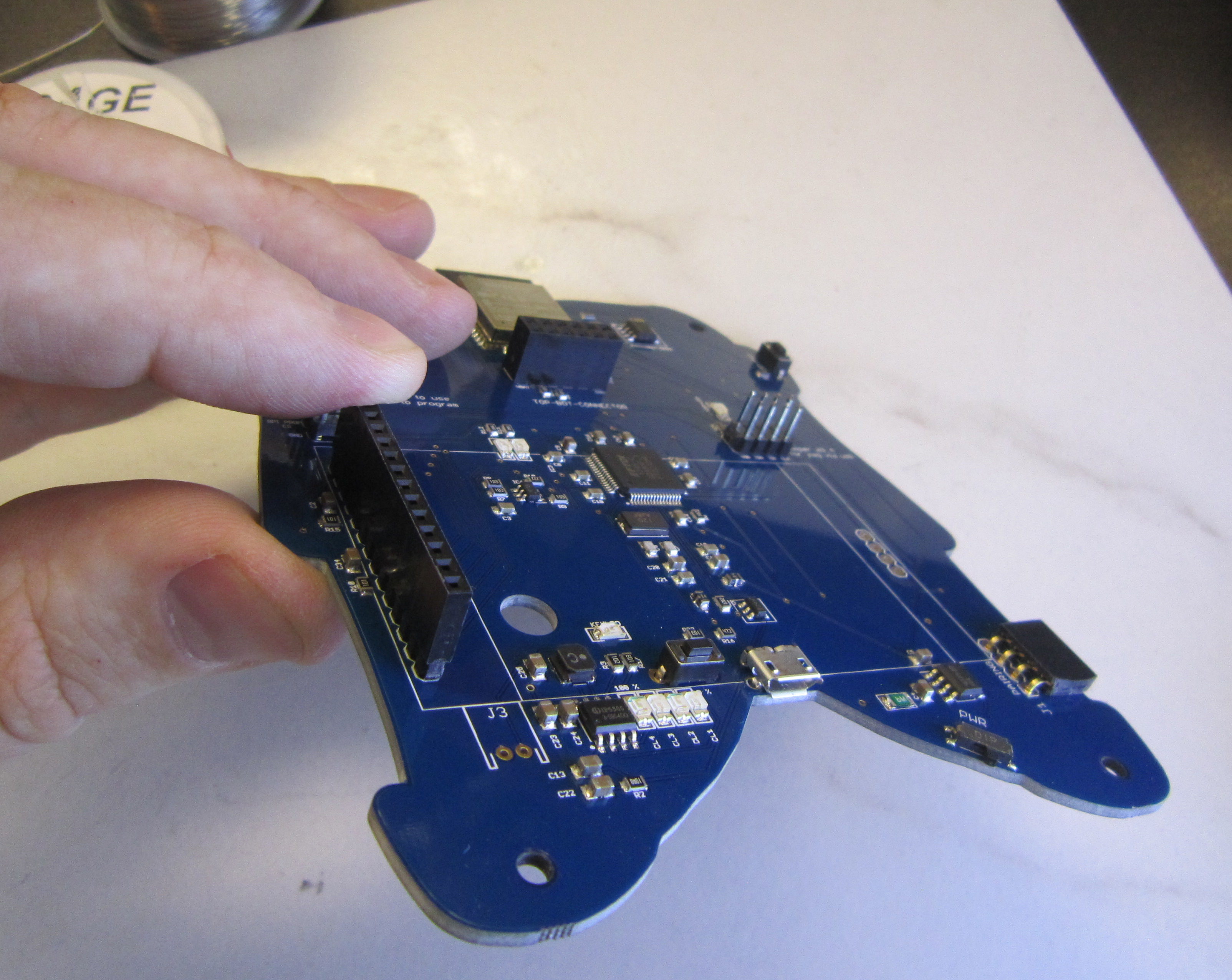
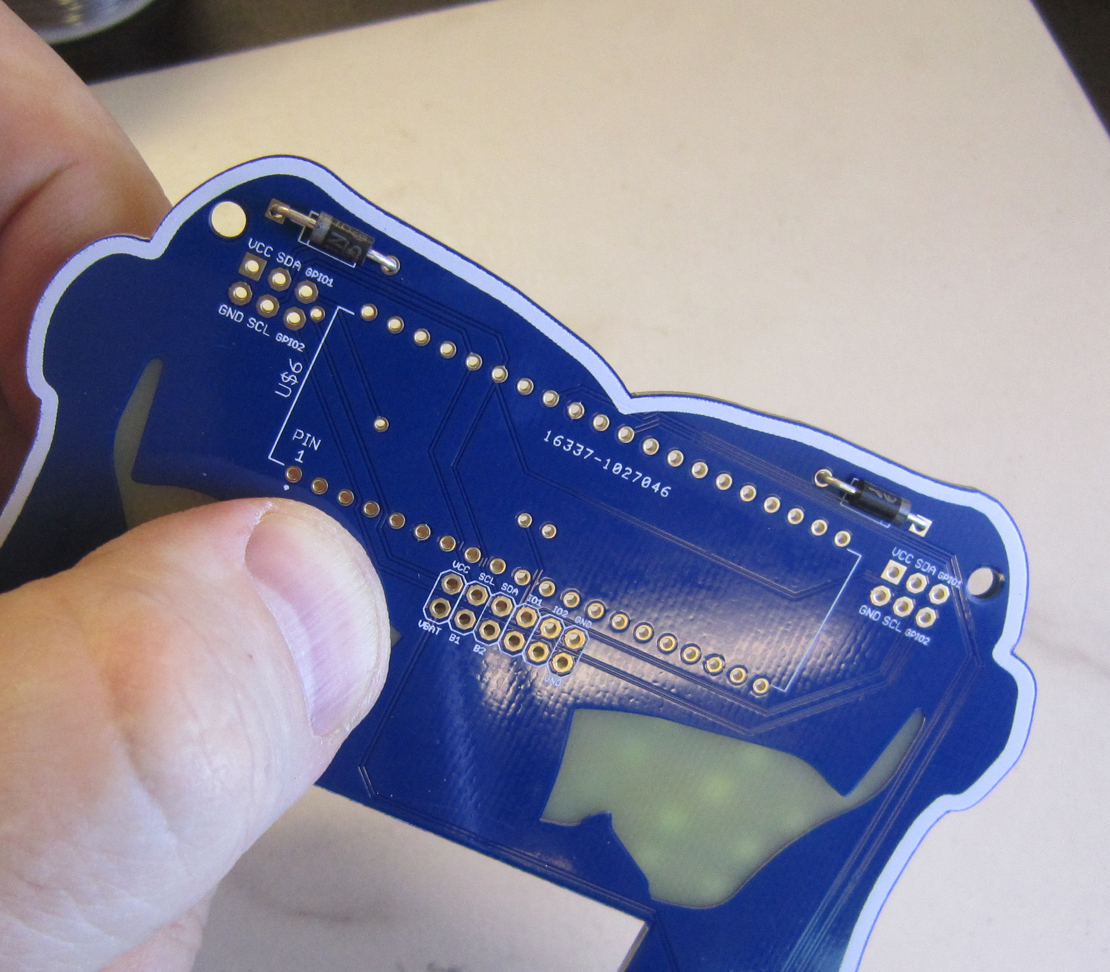
Next we'll solder the 2x6 female header for the board to board communications. By this point you should be good with ensuring parts are flush with the board by soldering a single pin, and then remelting the solder while holding the part to ensure it's placed correctly. This is importand for this part as it's required in order for the top board to mate propperly.

Included in the kit is a 2x10 male header. This needs to be carefully cut into a 2x4 male header and 2x6 male header. Cut the header in two as shown.
Install and solder the headers as shown.
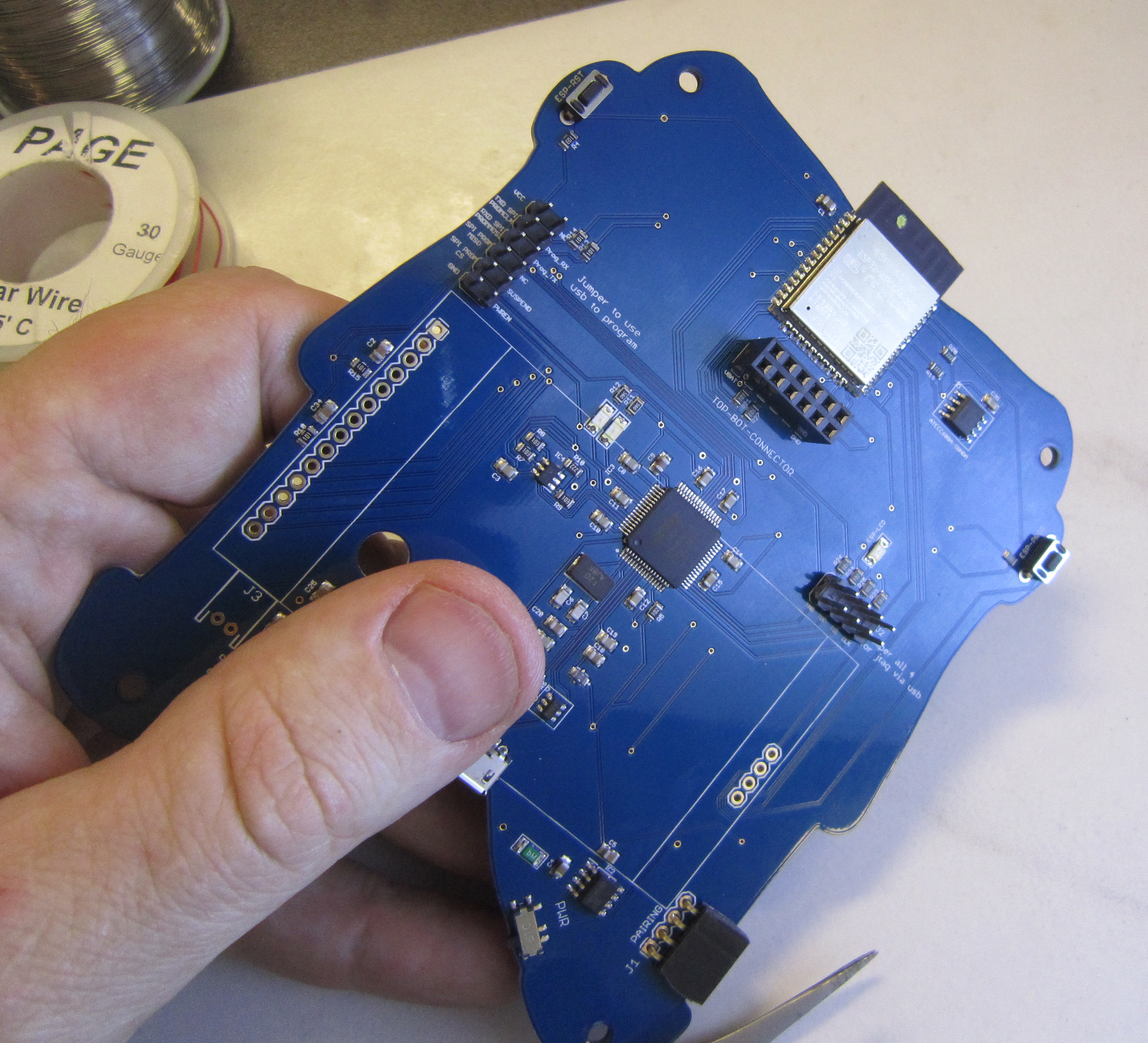
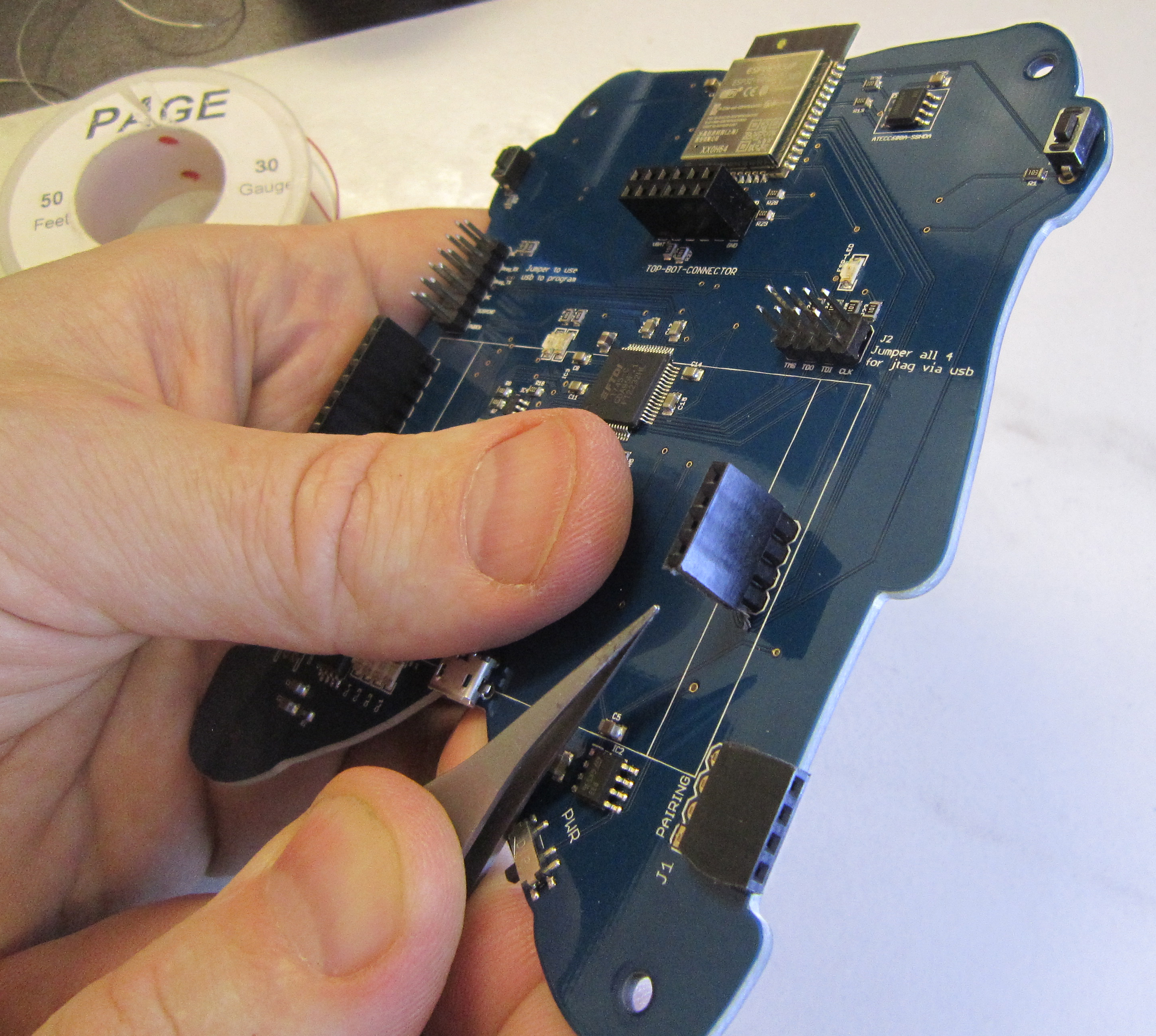
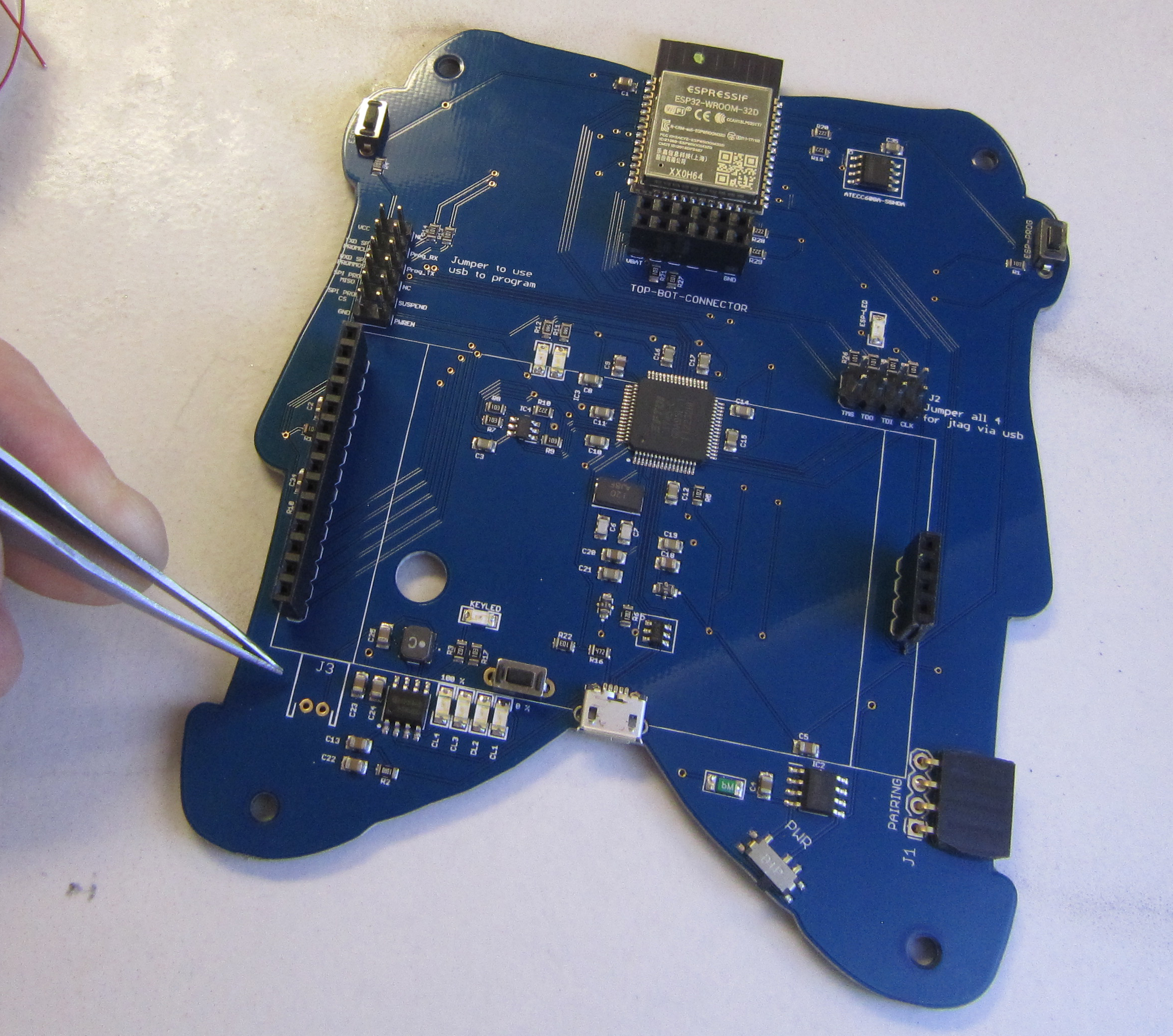
The two provided jumpers can be installed to program on Prog_RX and Prog_TX, or stored on the two pins marked NC for no connection. To program you also have to remove the top board and jumper SCL to GND on the board to board connector.
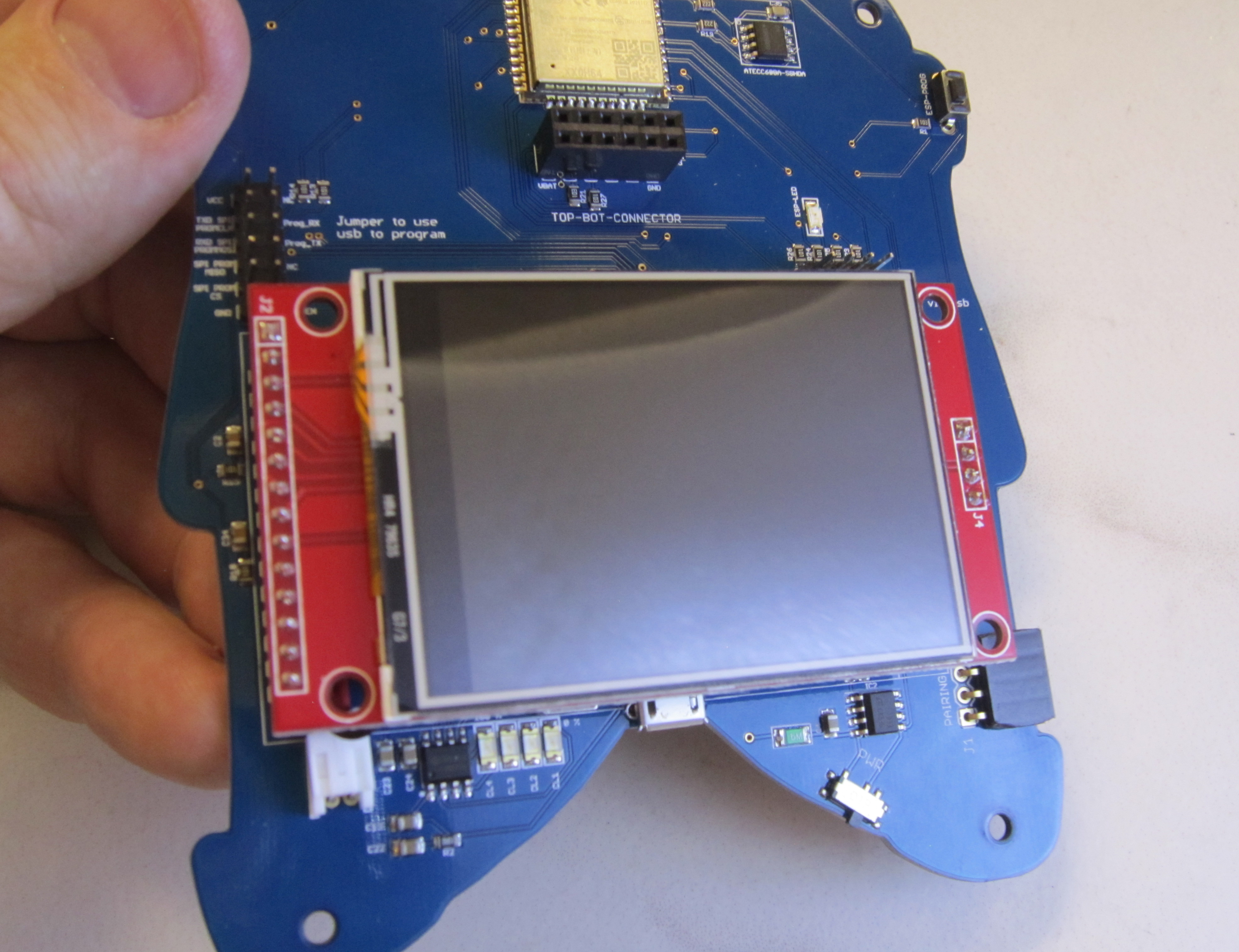
In order to make space for the LiPo battery under the display, we provided female headers which are extended to make up for manufacturing tolerances we found with the displays and batteries. Solder the two headers in place as shown.
The LiPo battery connector is located at J3. Note that this should be positioned so the plug faces toward the center of the board as indicated on the silk screen.
Now solder in the JST connector for the battery.
Trim the leads after soldering to prevent them from accidentally shorting with one another.
Next be adding the four pin header to the LCD.

Solder in place, and set the LCD aside. We will be installing the LCD in a later step.
This guide will cover one of the easier methods of surface mount soldering by hand without additional flux.
There are three bypass capacitors needed for the top board microcontroller. The SMD resistors are not polarized and can be installed in either orientation.
We'll start by tinning one of the solder pads. I am right handed, so I'm choosing the right most pad in this case. Add solder so there is a very small dome of solder.
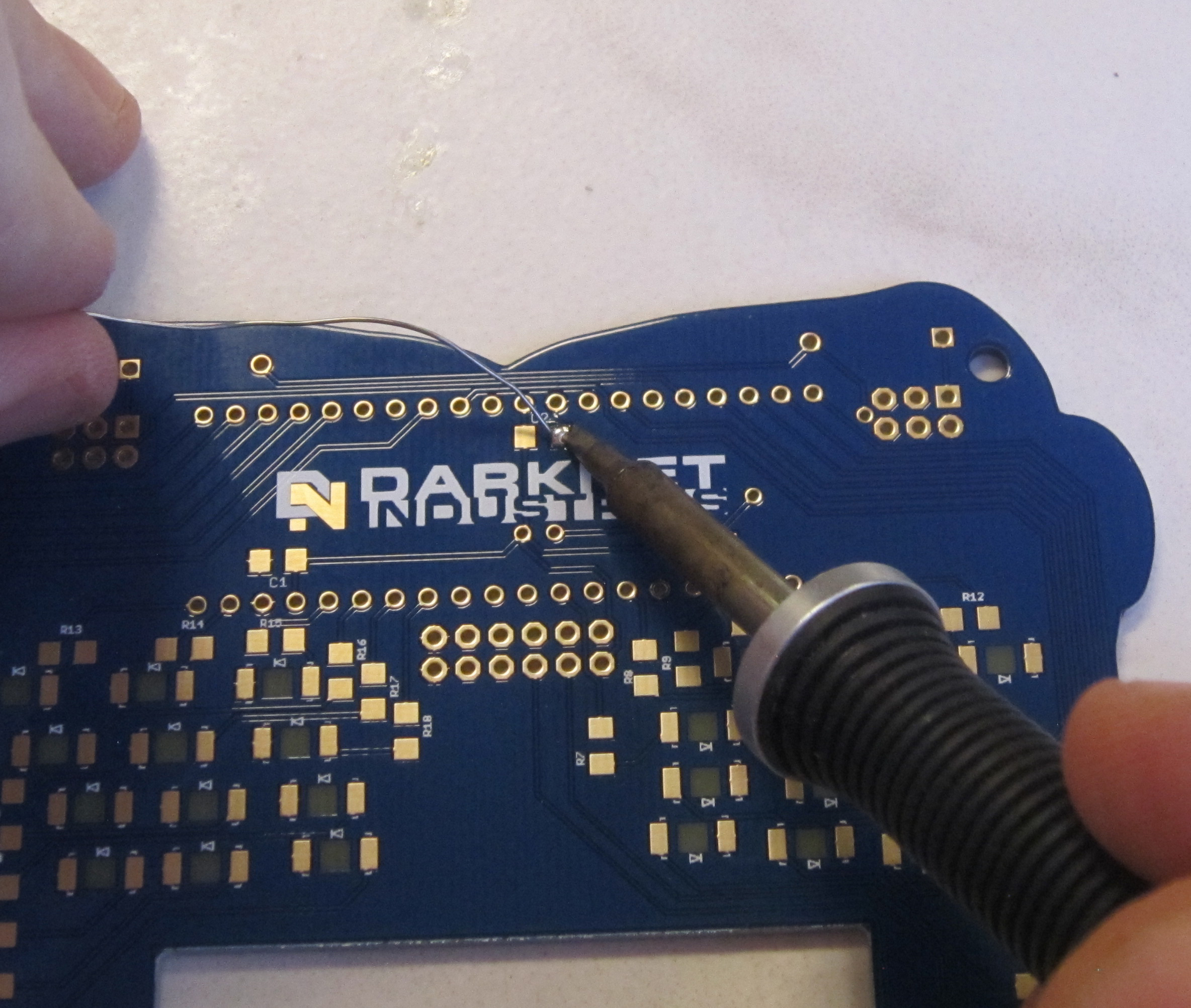
Next using tweezers hold one capacitor so you can guide it into place centered between the two SMD pads. Use your soldering iron to melt the solder on the pad you already tinned when doing this. Then remove the iron while holding the part still and in place. If the part is not centered you can melt the solder again and rework as needed. While there is flux in solder already, it can help to add a little flux if you are having problems with this step. Though you will need to clean the flux off after with alchohol if adding additional flux.
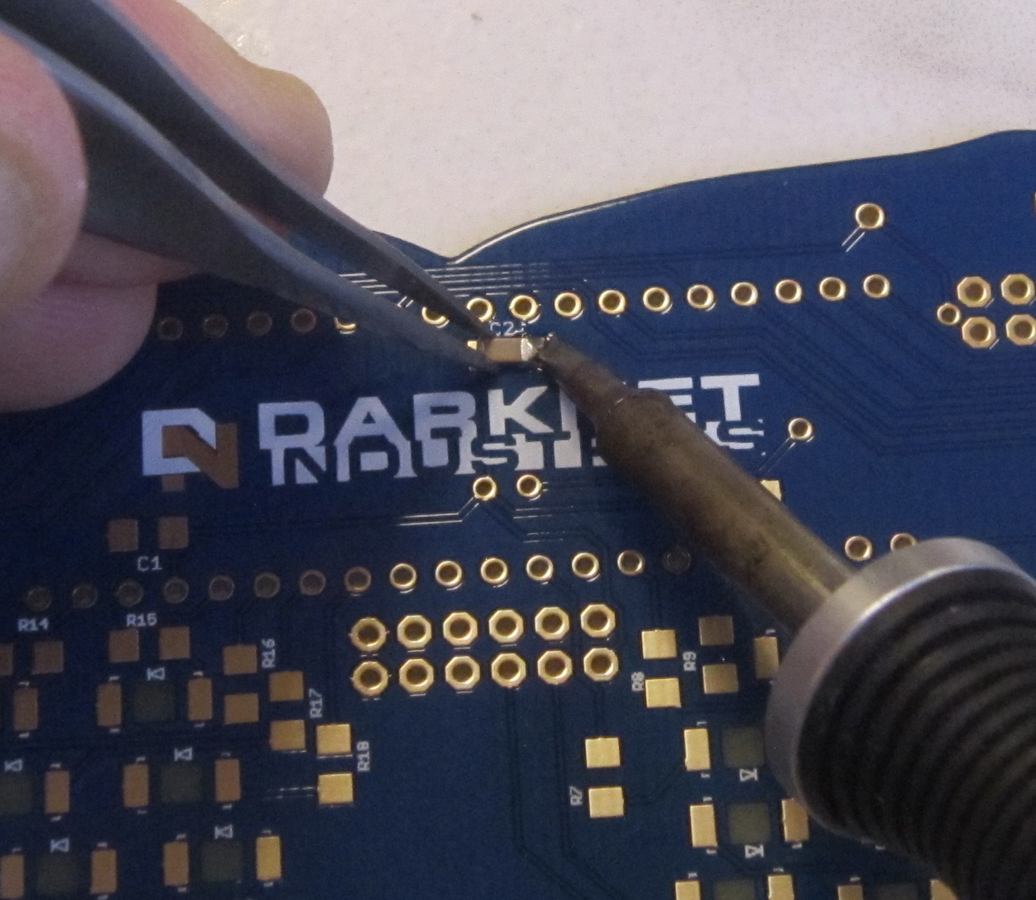
Now once the part is in place you can solder the remaining pad. If needed you can also go back and add additional solder to the first pad. Like through hole soldering you want a nice concave slope of solder which has wetted the part and the pad being soldered. If needed you can remove excess solder by either using solder braid for lots of excess, or use a clean iron to wick away small amounts.
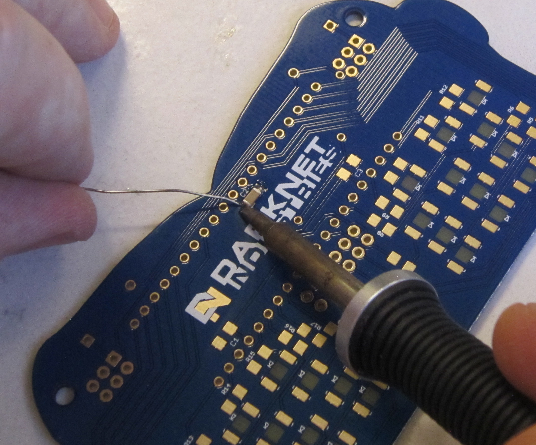
Repeat for the remaining two capacitors located on the under side of the top board MCU.
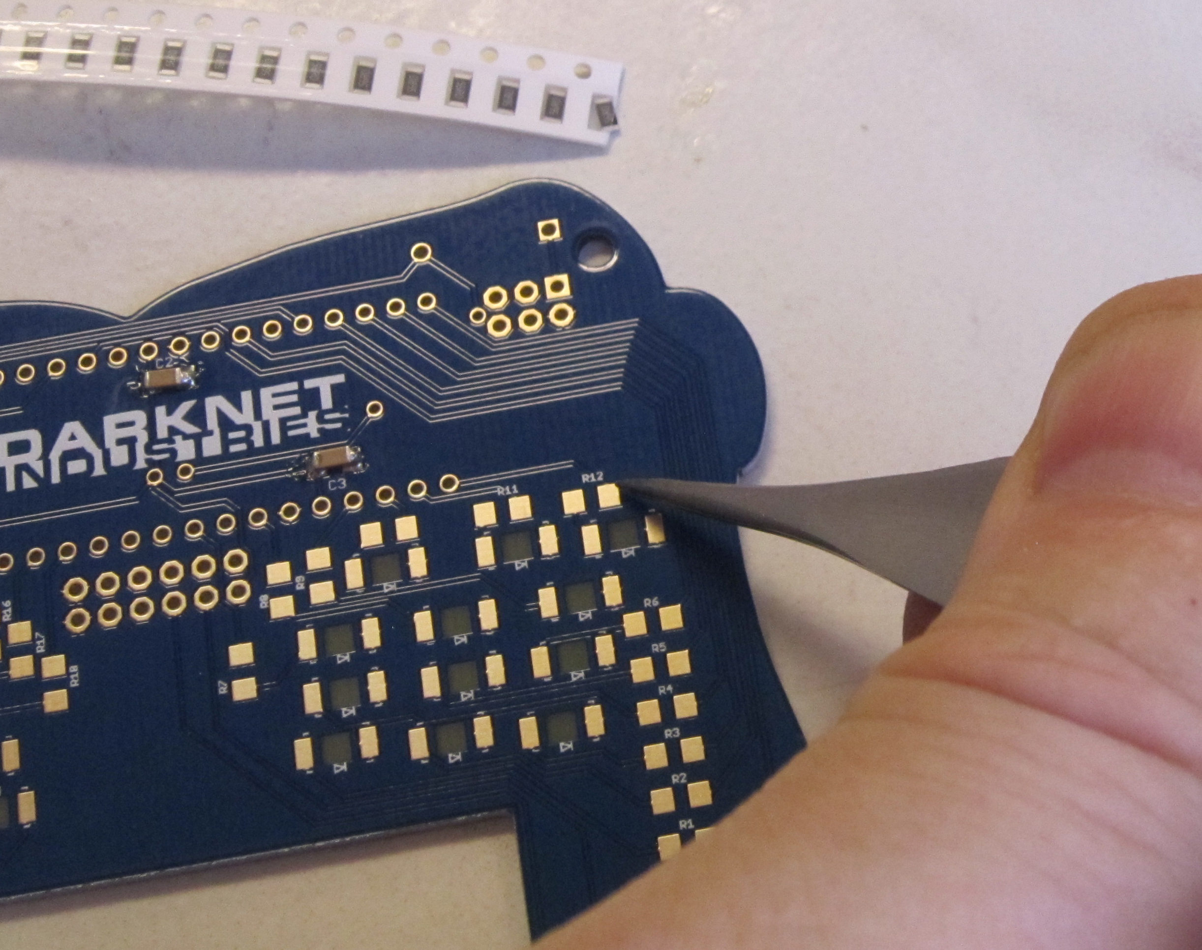
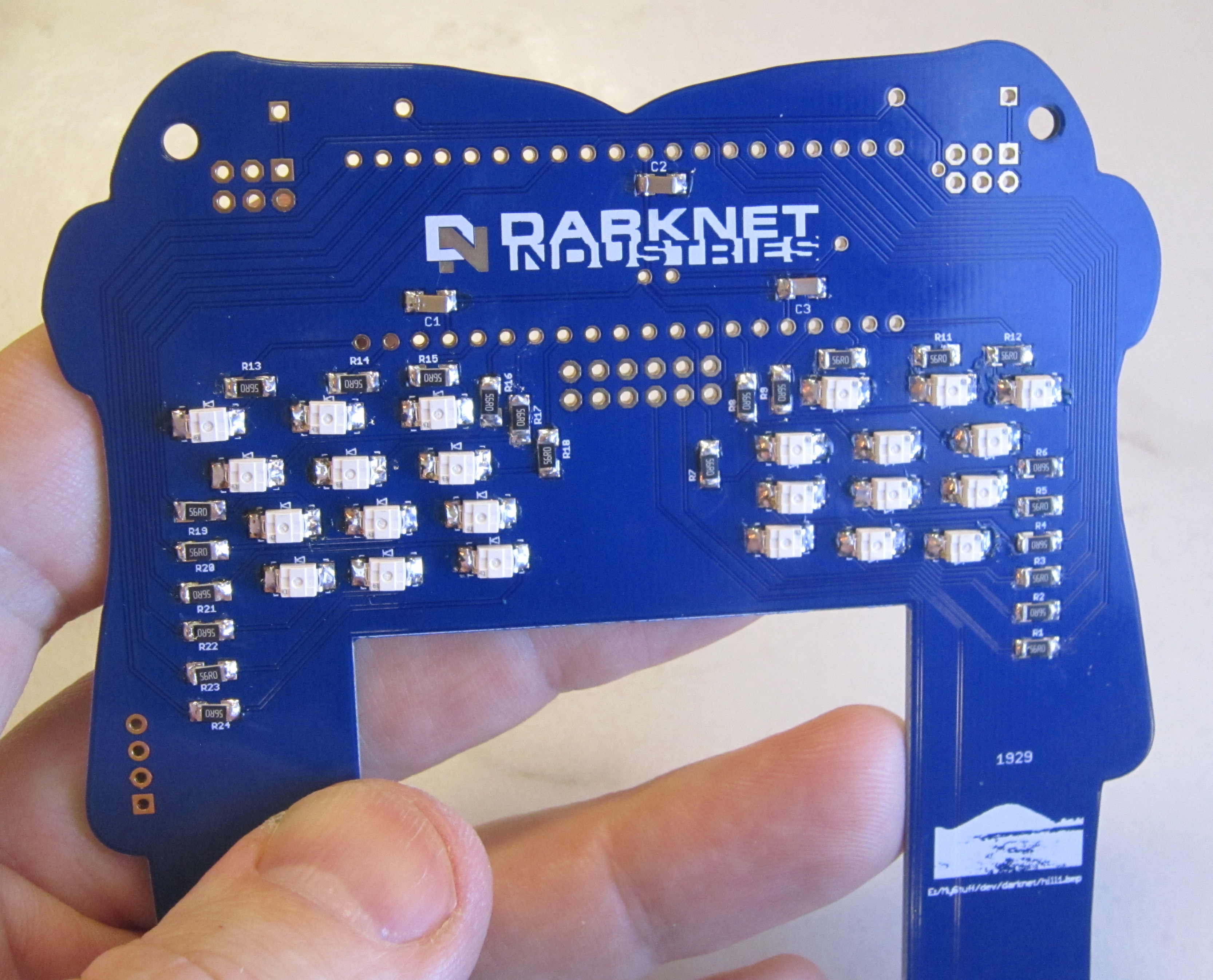
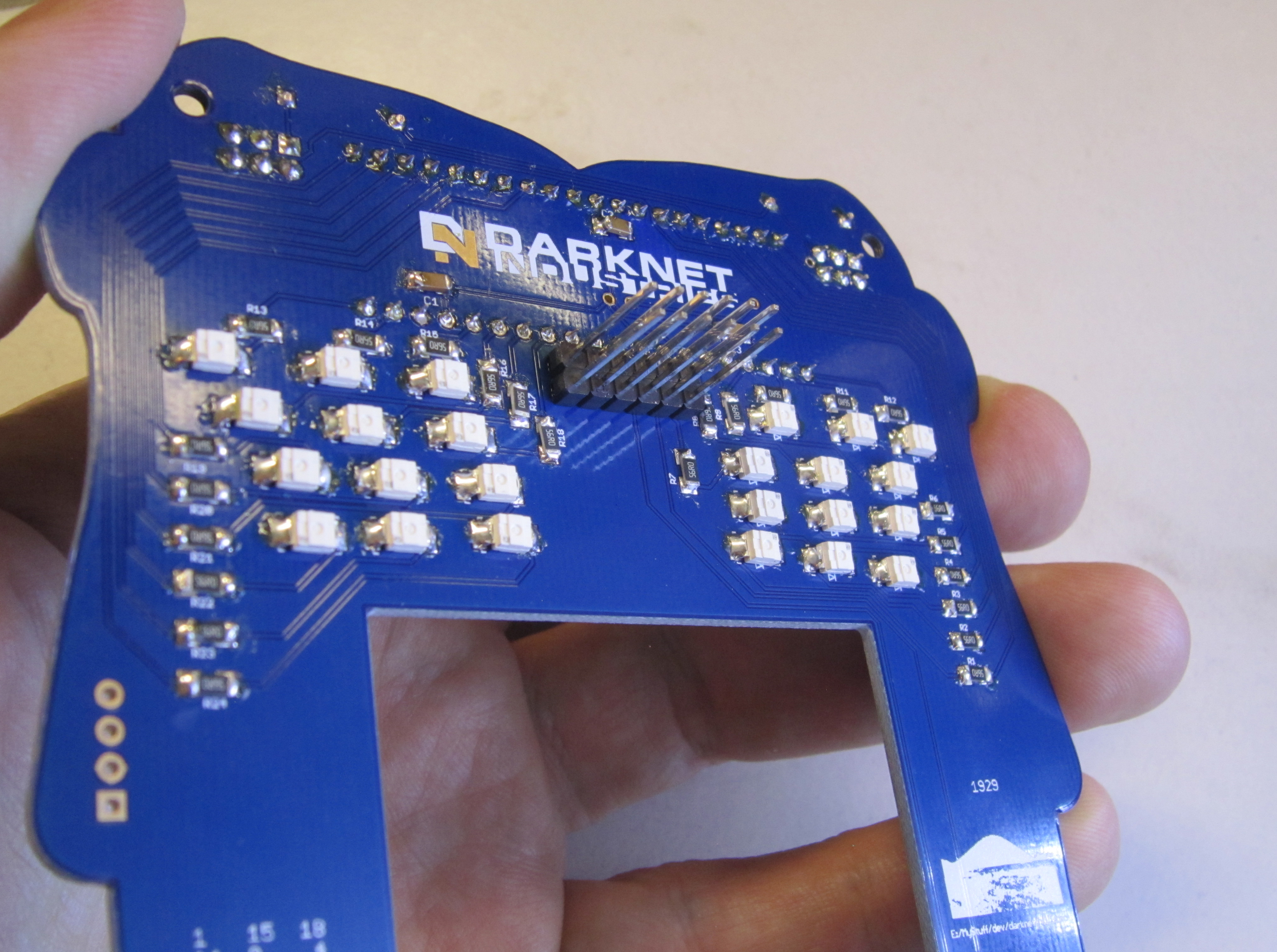
There are 24 LEDs, and each LED has it's own resistor. The resistor pads are marked with R##. There is one pad on the right hand side which is not marked but it is the same size as the other resistor pads.
As there are many resistors to solder, it helps to do the same step on all the parts. Start by laying out your resistors on your work surface so they are all face up. The top side of the resistor is black and will have small writing on it which indicates it's value. Resistors are also not polorized so they can be installed in either orientation.
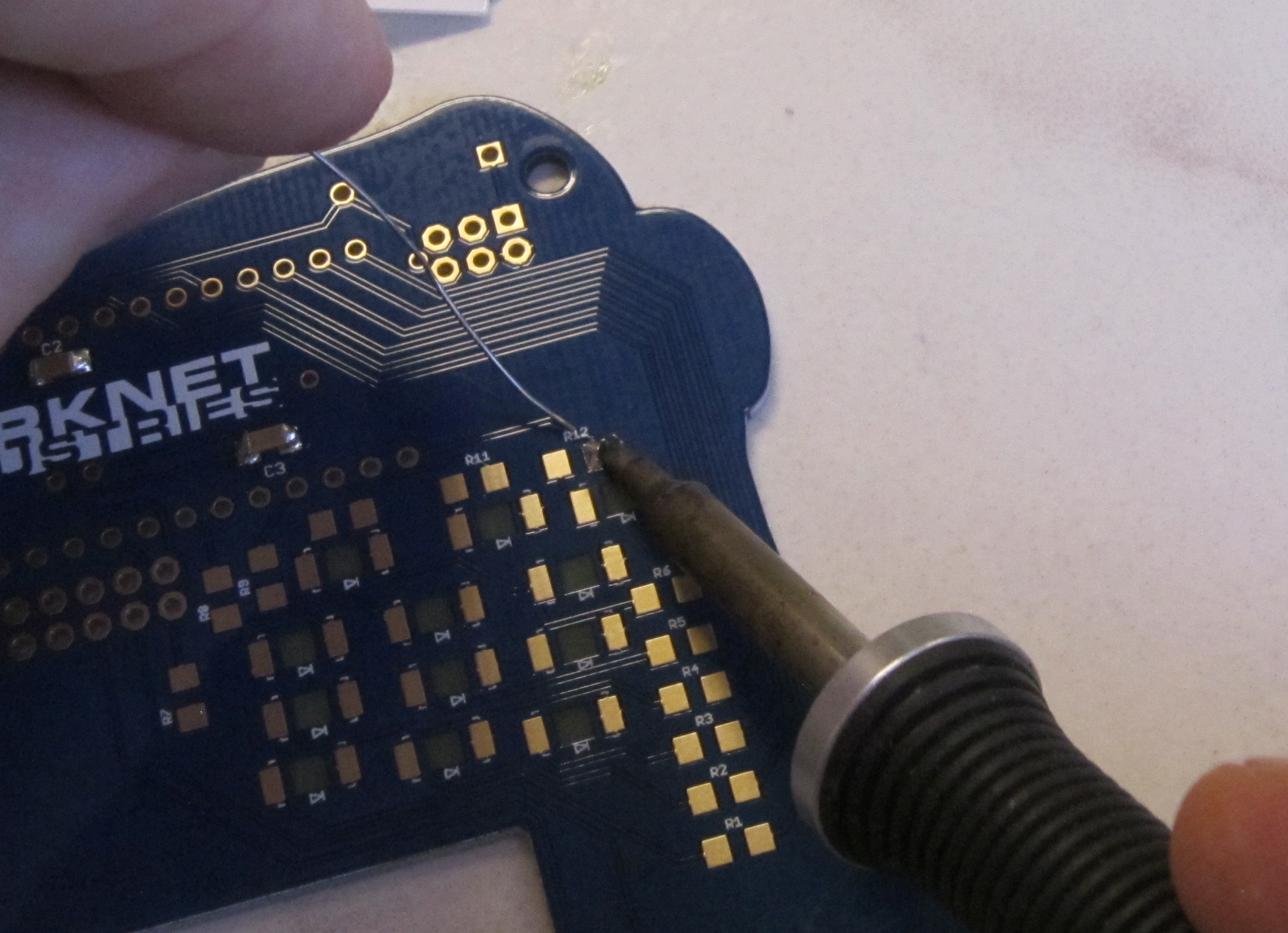
Next tin one pad on each of the 24 resistor pads.
Note that the resistors in the center are orientated vertically instead of horizontally.

Next using the same technique you used on the capacitors, solder one lead of each resistor in place.
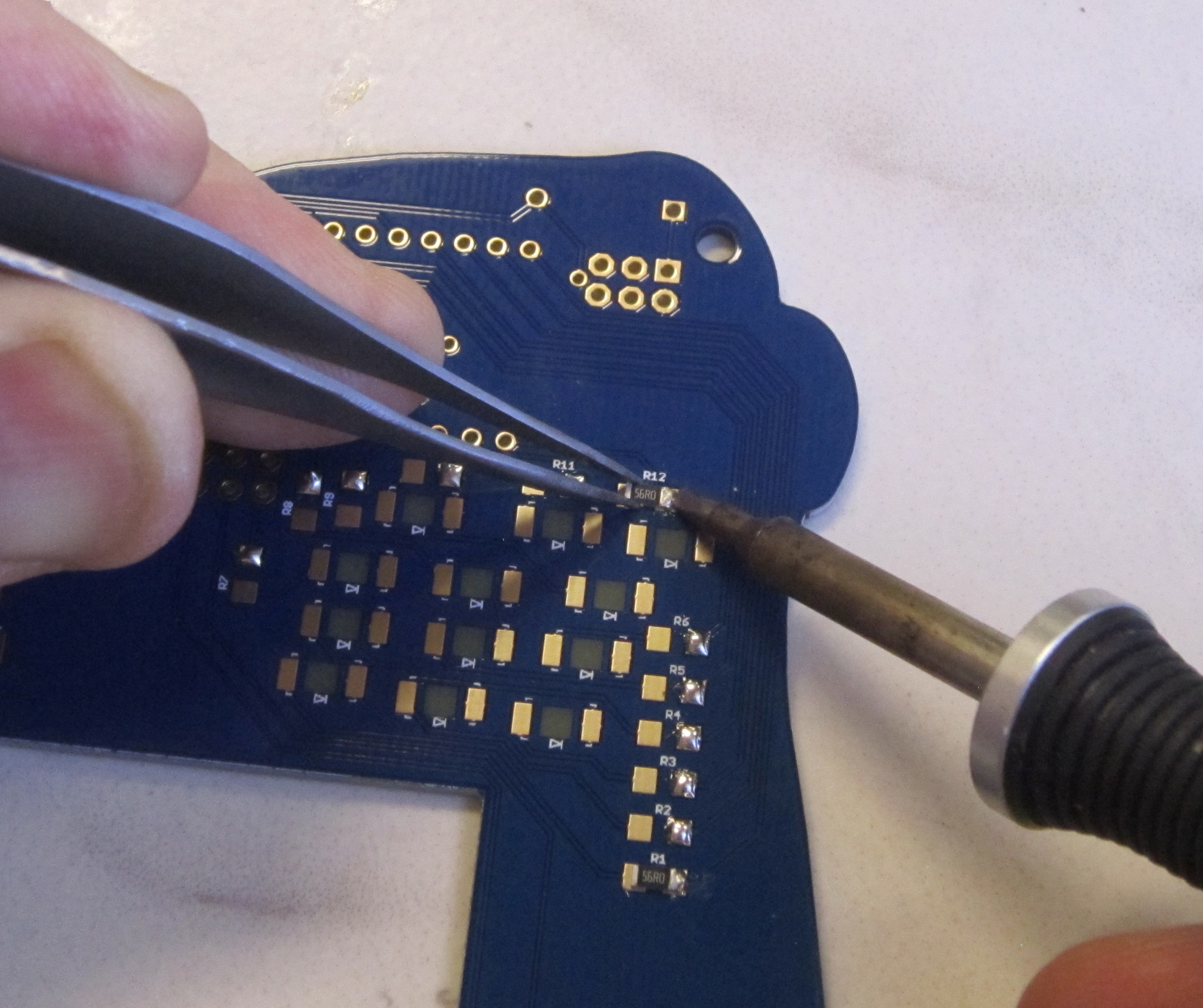
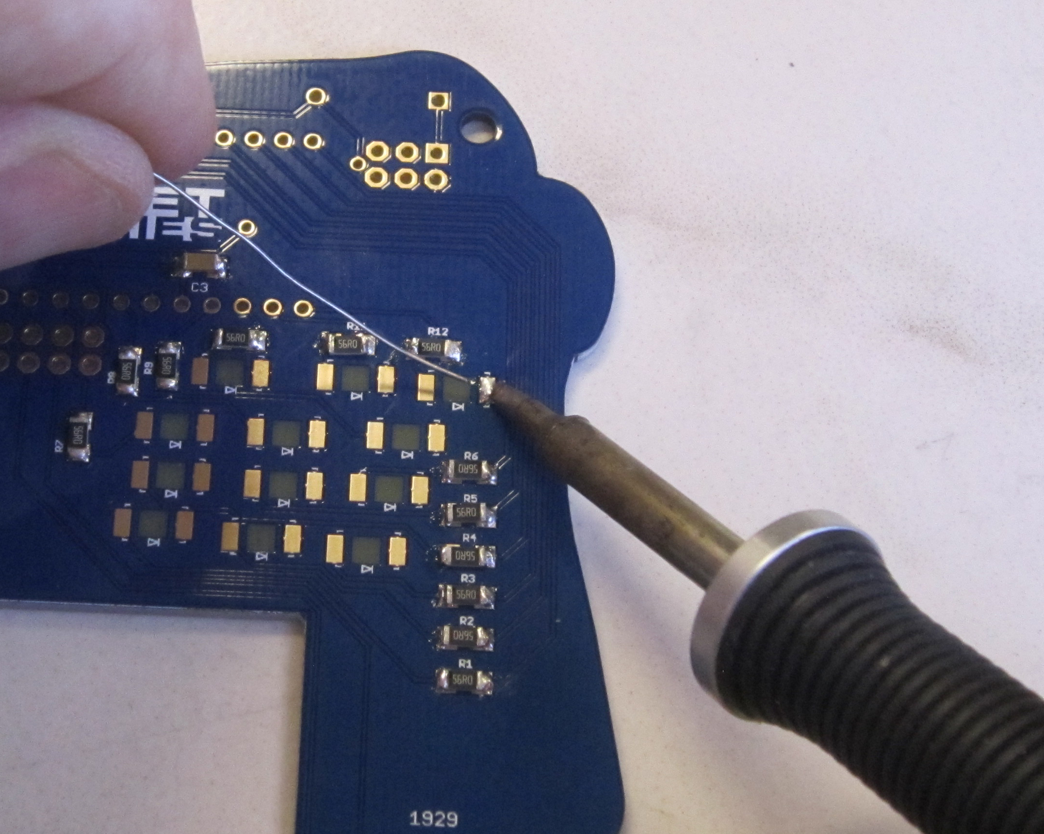
And finally solder the other pad of each resistor.
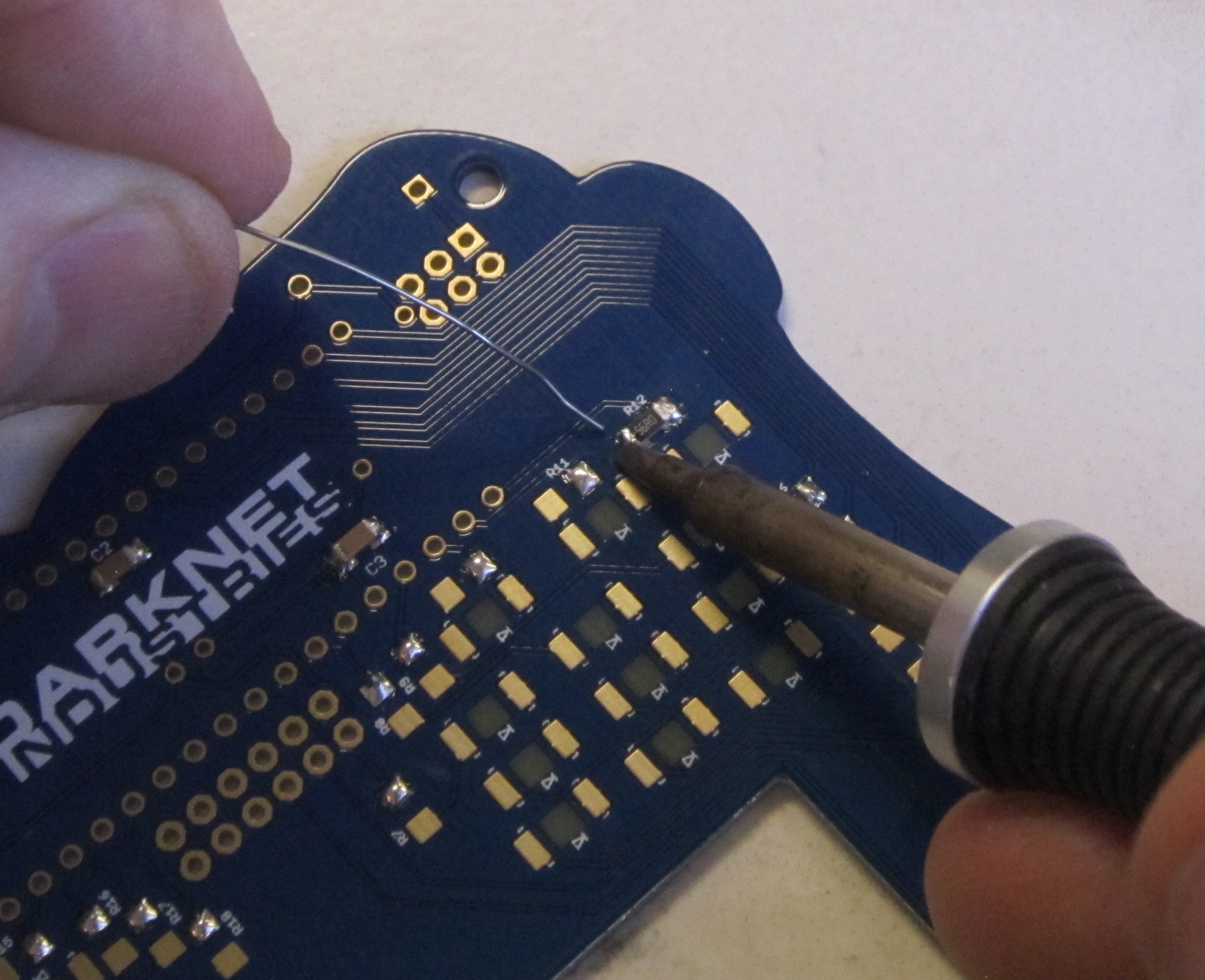
Next we'll be soldering the LEDs. Unlike the other parts, LEDs are polarized, so they will only work if soldered in the correct orientation.
Start by tinning one pad for each of the LEDs.
Next we'll organize our parts. On the LEDs you can see a small dimple in one corner which indicates the cathode.
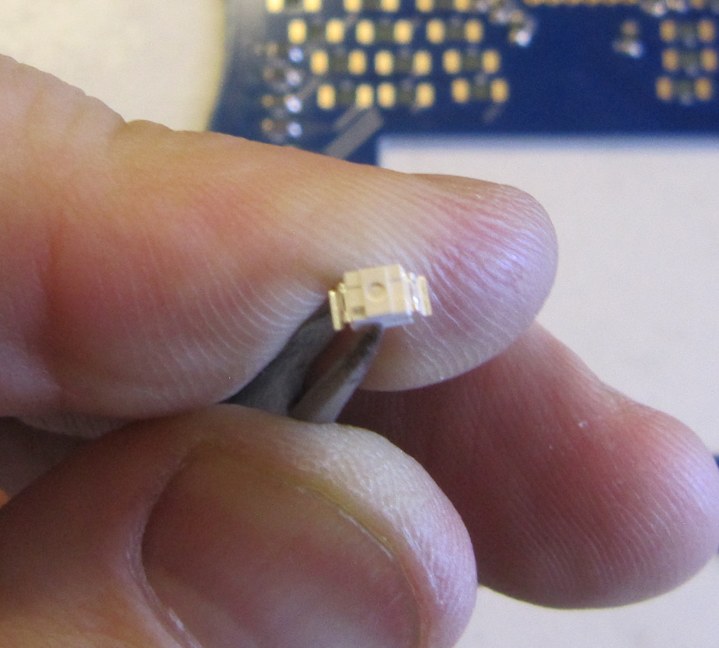
The board is also marked with the LED orientation using the diode symbol.

Note: Not all of the LEDs and Diodes are in the same orientation on this board. The LEDs on the right half of the board face one direction and the ones on the left half of the board face the opposite.
Knowing this, take a moment to arrange twelve of your LEDs on your work surface so they are all right side up, and oriented facing in the direction they will be soldered on for the right side of the board. And the same with the other twelve LEDs, but oriented for the direction they need to be facing for the left side.
Like the other SMD parts solder one lead in place for each of the LEDs. You can also choose to solder a single LED first to get the feel for soldering the LEDs before moving on to soldering the rest of them in place. I find that it helps to move the tip of the iron along the edge of the LED lead while holding the LED in place to help the solder flow nicely.
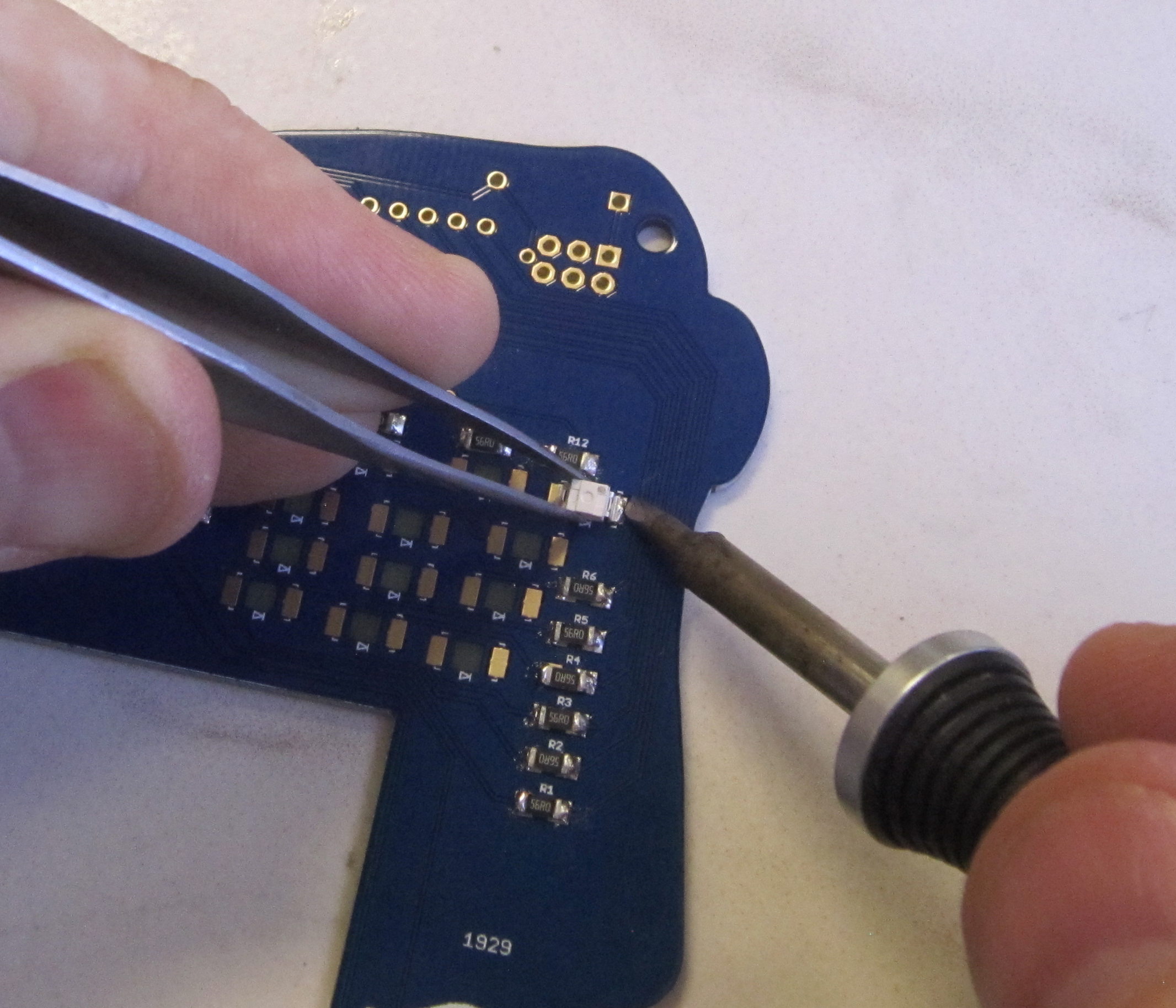
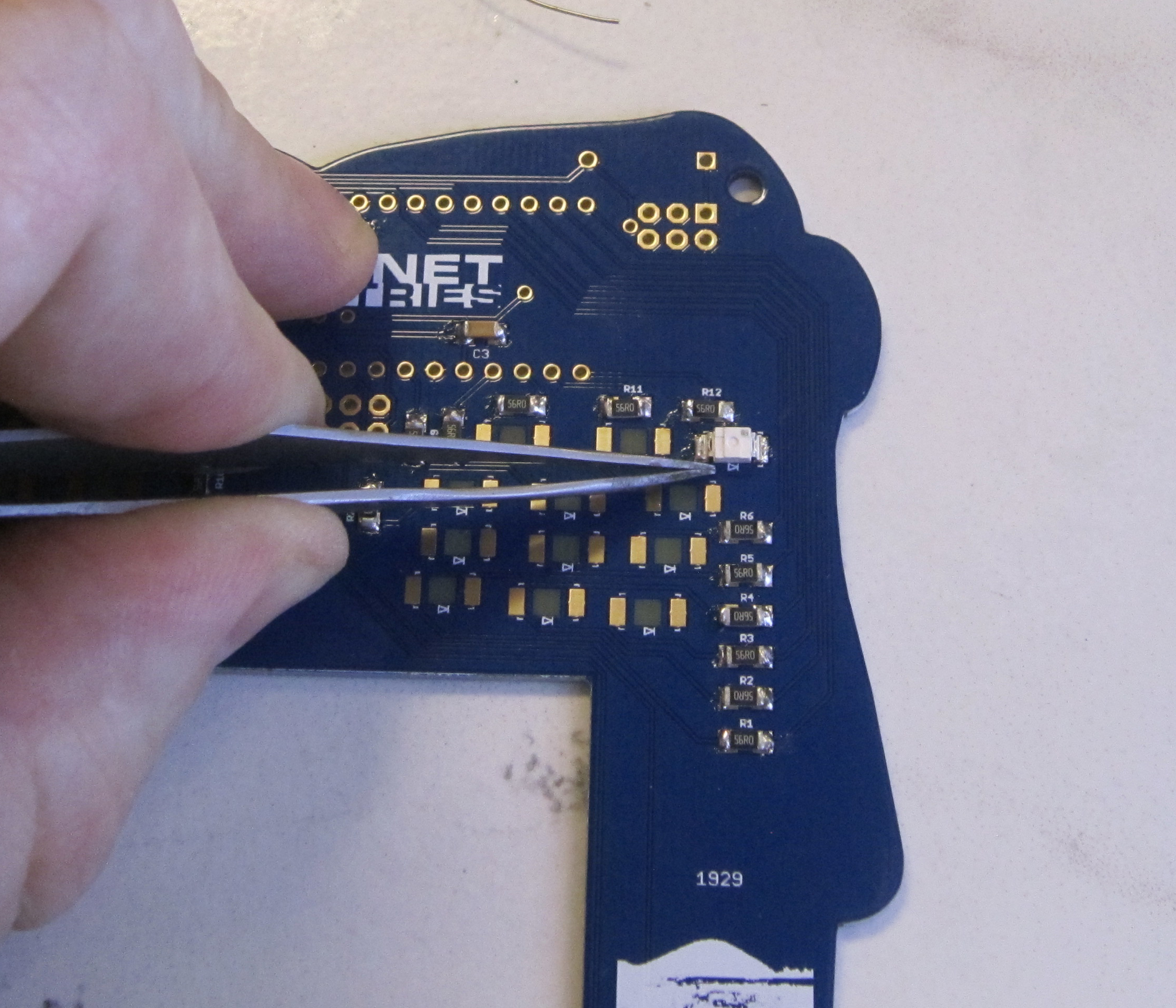
Once all your LEDs are in place, solder the other side of the LEDs.
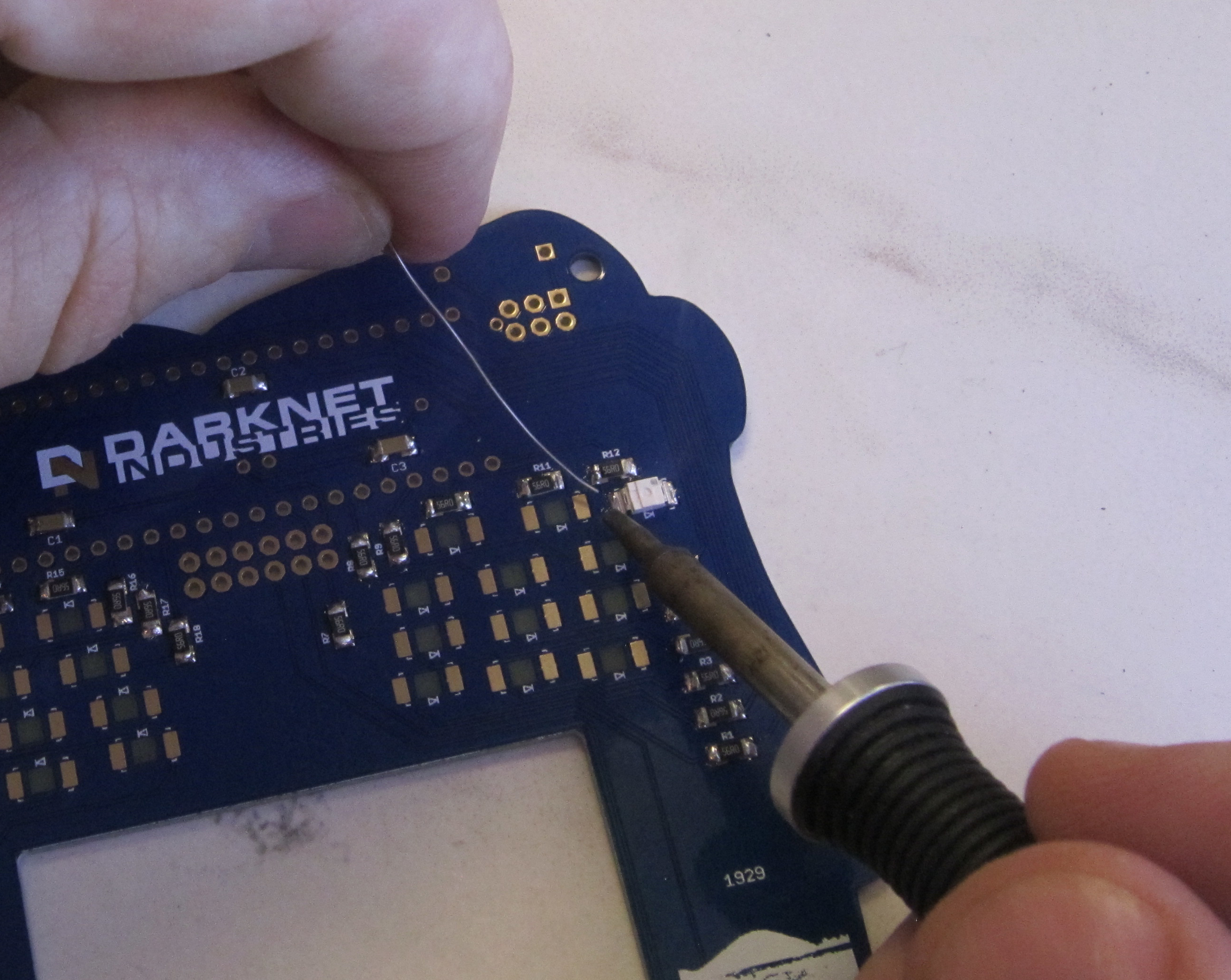
Finally once you have completed all the surface mount soldering, inspect your work to ensure that you have soldered both pads of all the components.
There are two protection diodes for the SAO connectors. Helps to prevent back feeding power into the badge and potentially damaging it. Like LEDs, the diodes also have a polarity, and are marked with a stripe indicating the cathode.
Using needle nose pliers bend the Diode as shown.
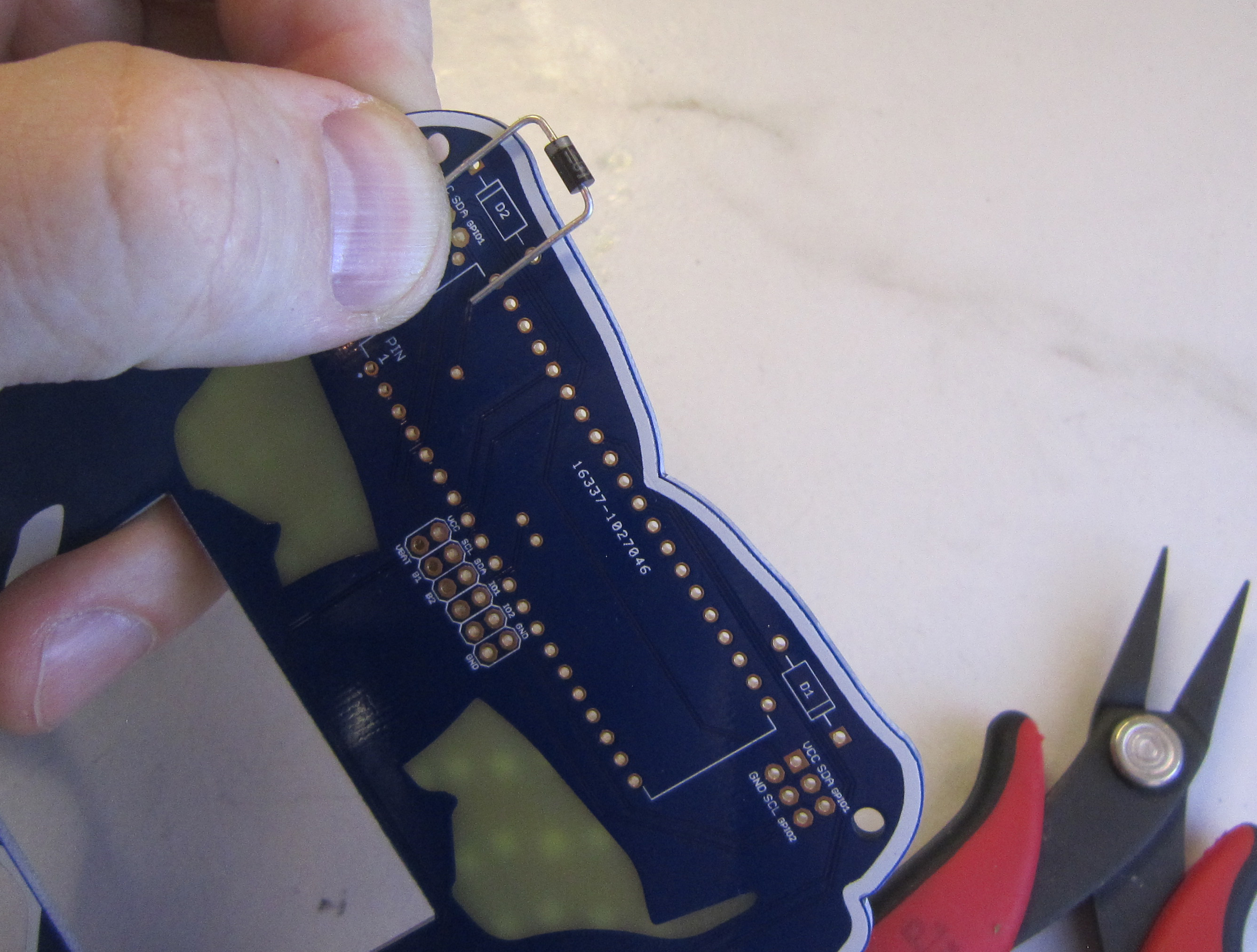
Install the diode and solder in place.
Next solder in the opposite diode, making note of it's polarity to match the silk screen.
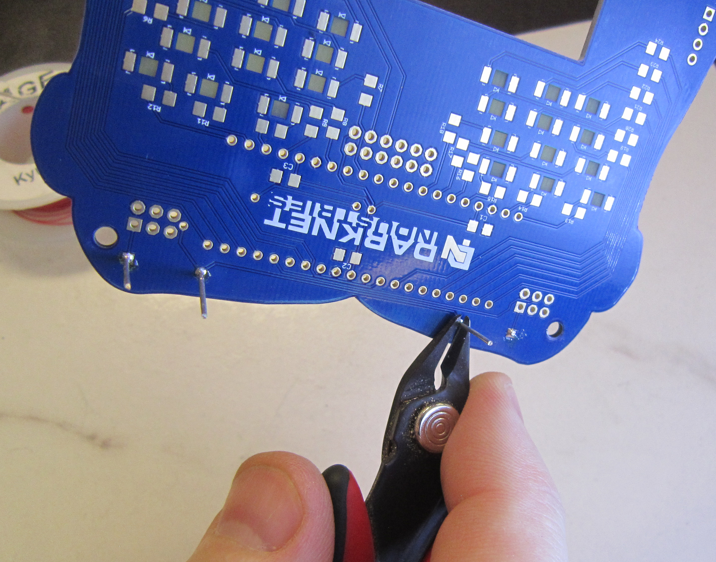
Trim the leads with flush cutters.
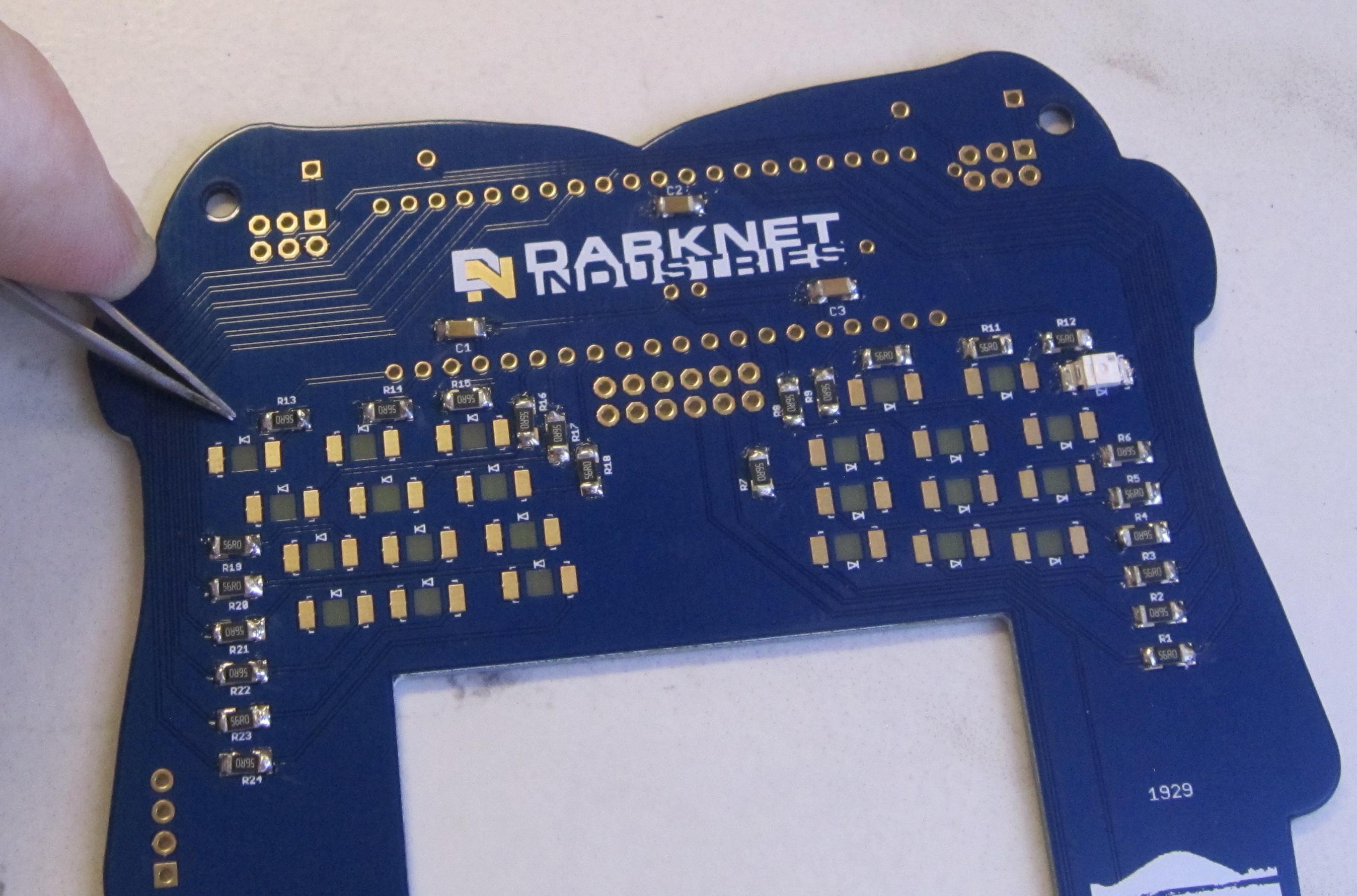
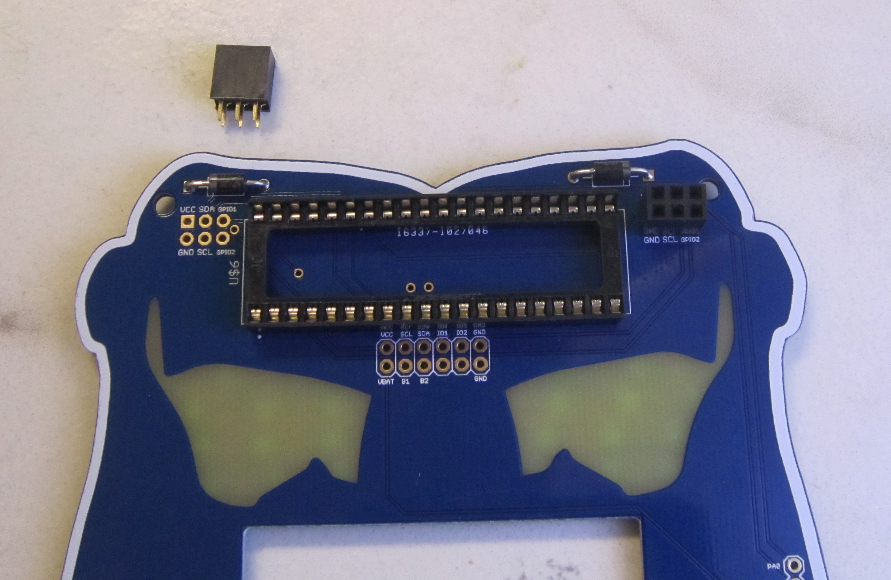
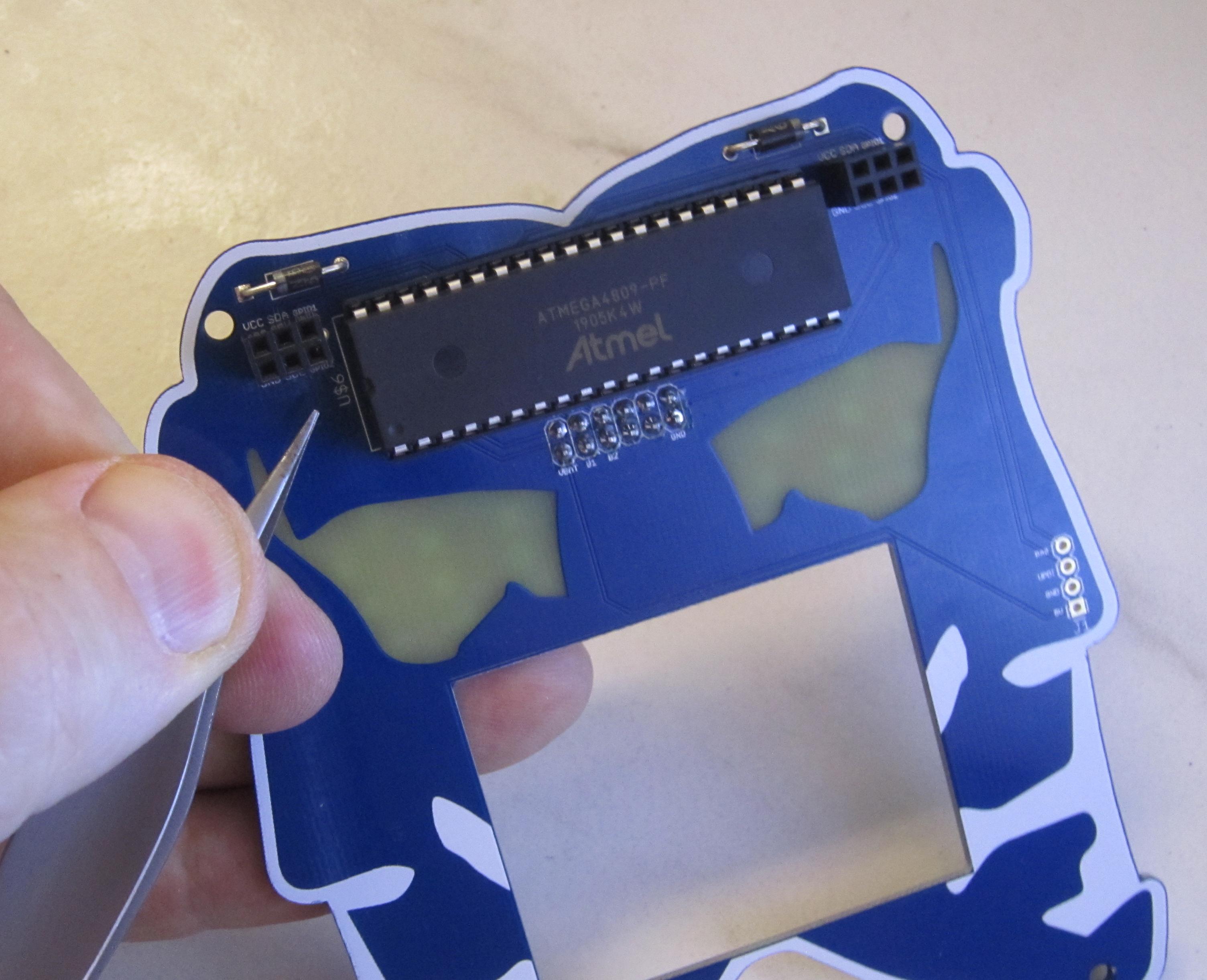
Next we'll be installing the 40 pin DIP socket. Pin 1 is marked on the silk screen as shown. This corresponds to the dimple marked on the end of the DIP socket, as well as the chip itself.

Next install the two 2x3 female SAO headers.
Solder in the two tactile momentary switches on the top board as shown.
Next we'll be installing the two six pin headers to connect the top board to the bottom board. It helps to solder these one at a time, starting with the header closest to the DIP socket. Like the other headers solder one pin in place, then if needed adjust so the header is flush and perpendicular to the board. Once soldered in place add the second six pin header.
Next install the Atmel 4809 microcontroller. Paying attention that Pin 1 is on the left hand side of the board as shown.
Carefully bend the lead of the LiPo battery as shown.
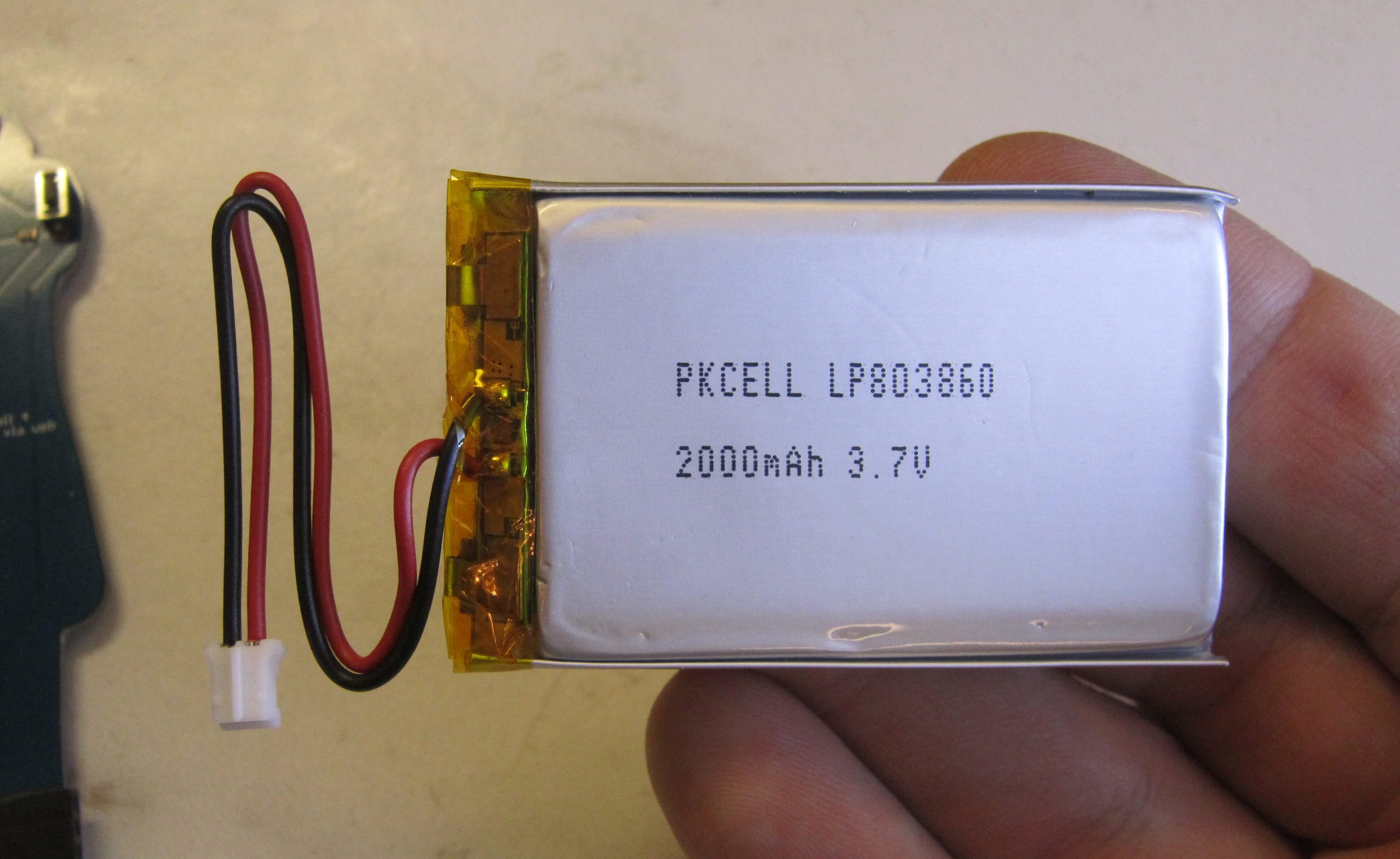
The LiPo batter is installed under the LCD. A small 3/4" x 3/4" square of thin foam tape at the bottom right corner of the battery where the PCB is flat and clear of components should be used to keep the LiPo battery in place.
Install the battery as shown.
Next plug in the display module.
Next we'll be installing the hardware to connect the top and bottom badge assemblies together.
Included are four nylon standoffs, washers, nuts and screws.
Using the nylon washer between the bottom of the standoff and the bottom board. Install and fasten the nylon nuts.
(note in this picture we didn't have the nylon washers yet, but they are required to take up the space between the top and bottom boards when everything is assembled)
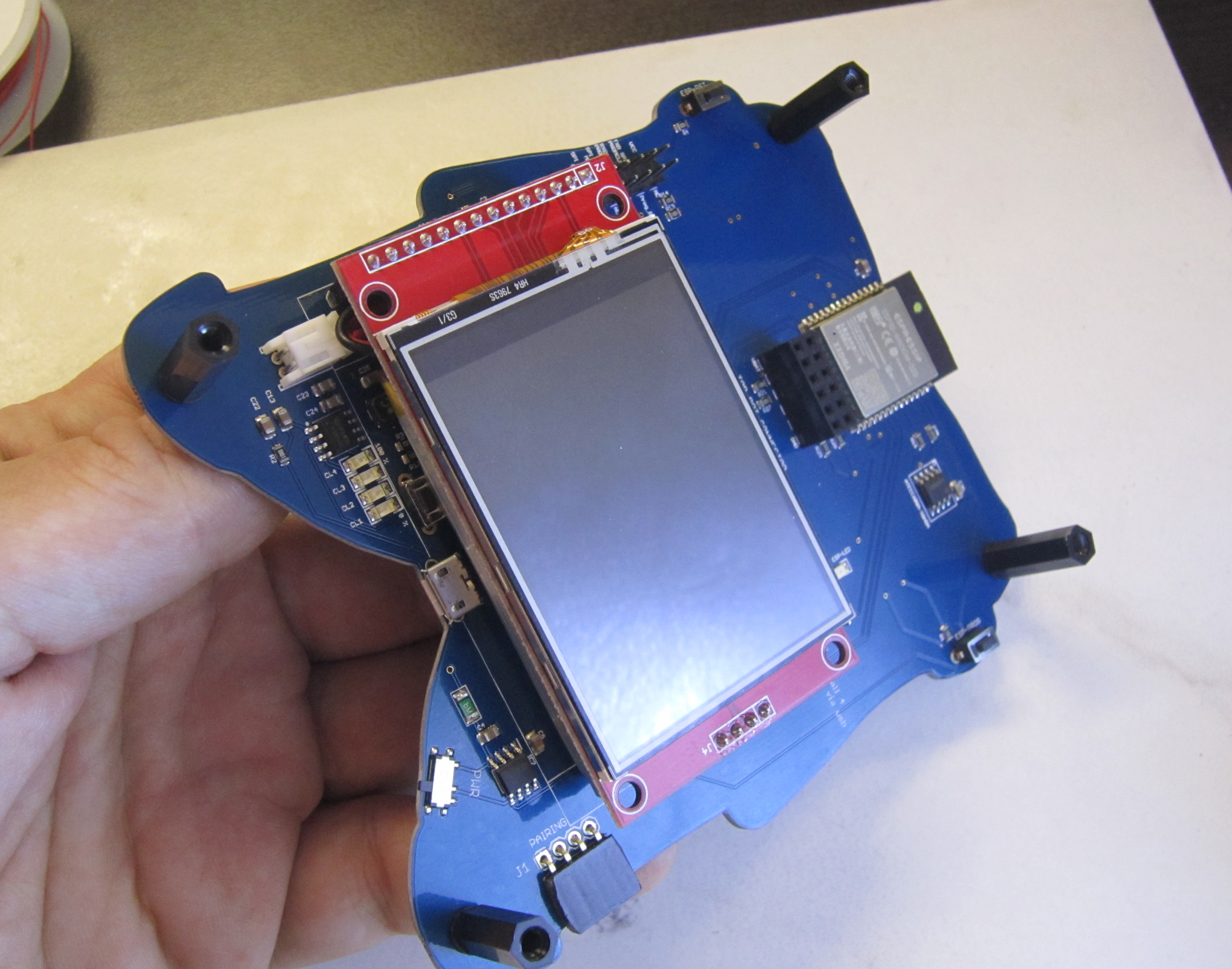
Plug the top board into the bottom board, and fasten the four screws.
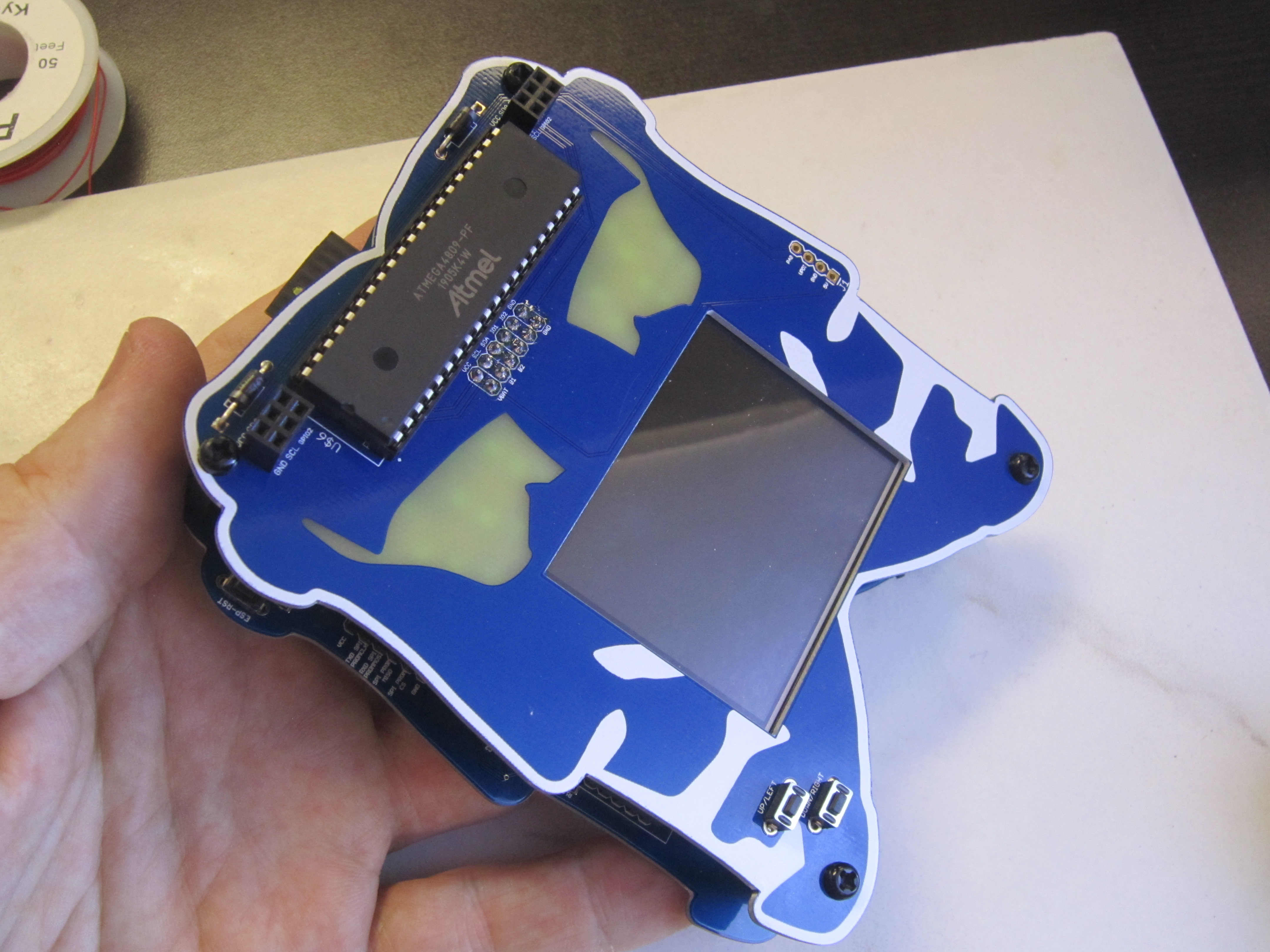
Your badge is now complete. Power on your badge and test out it's functionality. We hope you really enjoy this year's Darknet 8 badge, and had fun assembing it.
There are several challenges associated with the badge for this year's Darknet contest. Find other players who have badges. Solve the badges silk screen puzzles. Extend the firmware and make your badge do new cool stuff.
![]()
![]()
The following are some of the items we've noted with the badge:
- Traces were run through the copper element of the bottom board silk screen puzzle. This should not cause an issue, but you may want to add clear nail polish over these traces for added protecttion against accidentals scrapes which could cause a short.
- Some elements of the silk screen puzzles on both the top and bottom boards are not as clear as they were intended to be due to limitations on the board house's silk screening capability. Refer to the PCB source files for anything which may need to clarity. You may also PM Krux on Discord to get a screen shot if you do not have Eagle installed.
- There is not quite enough clearance on the left SAO header if used with a shrouded SAO header.
- We were unable to get PWM working for the LEDs in the limited time we had to develop the firmware. If you figure out how to get Soft-PWM working reliably on all 24 LEDs, let us know.
- Due to the external I2C pullups, as previously mentioned, to program you also have to remove the top board and jumper SCL to GND on the board to board connector.