These are the assembly instructions for the DarkNet 2018 Badge Kit.
This badge not only is an excellent opportunity to learn how to solder, it is also a tool that is used to communicate with other agents participating in the DarkNet contest. It can be used to pair with other agent's badges, as well as is instrumental in several of the challenges you will encounter when playing with the DarkNet.
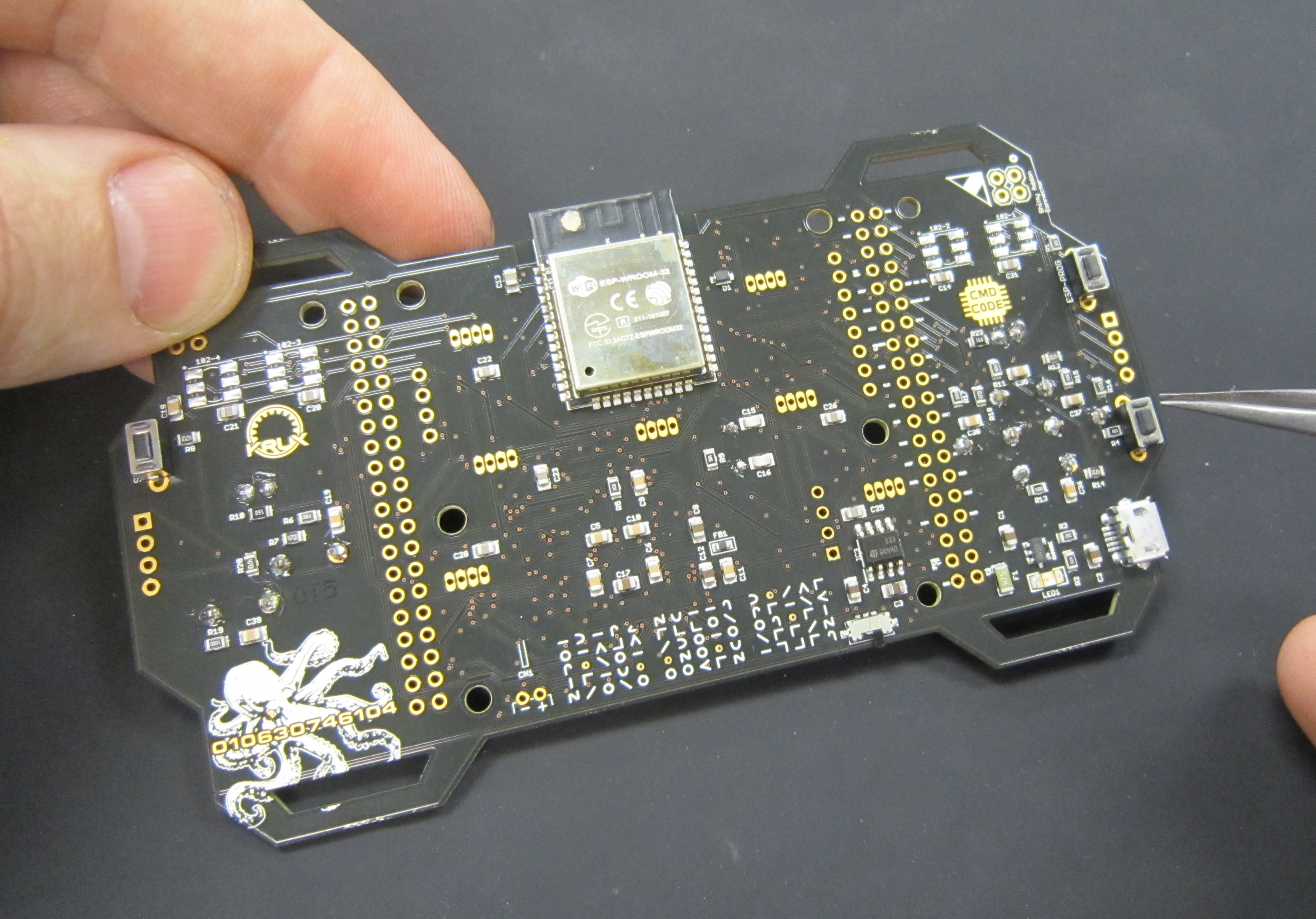
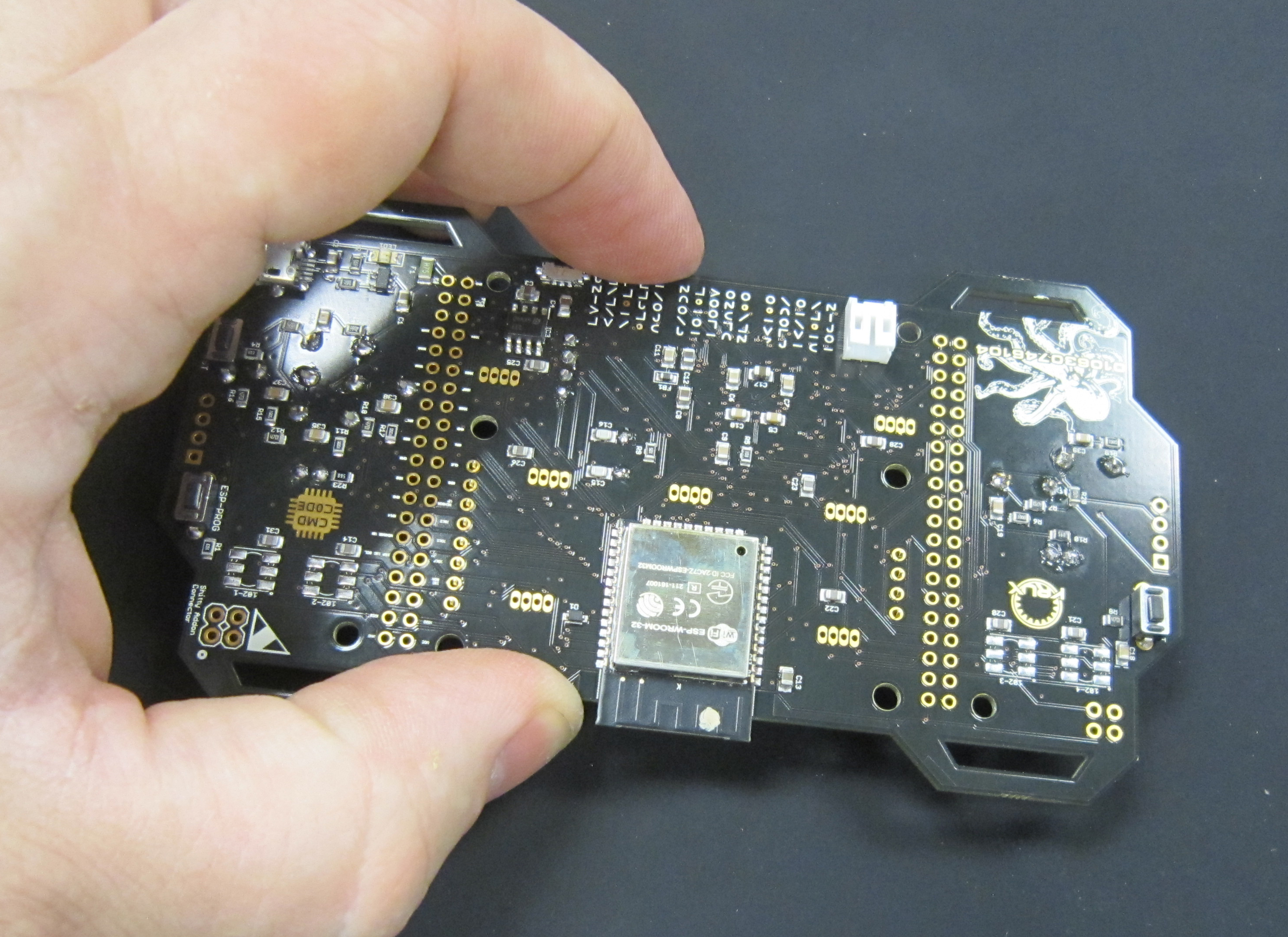
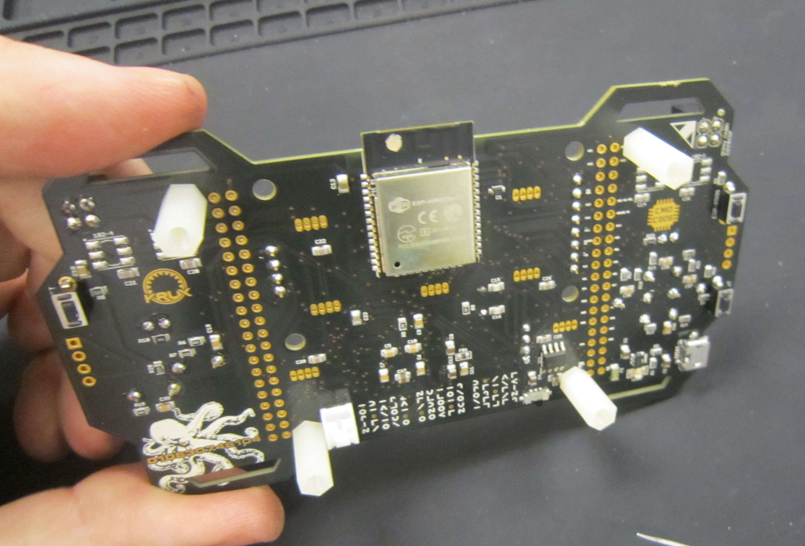
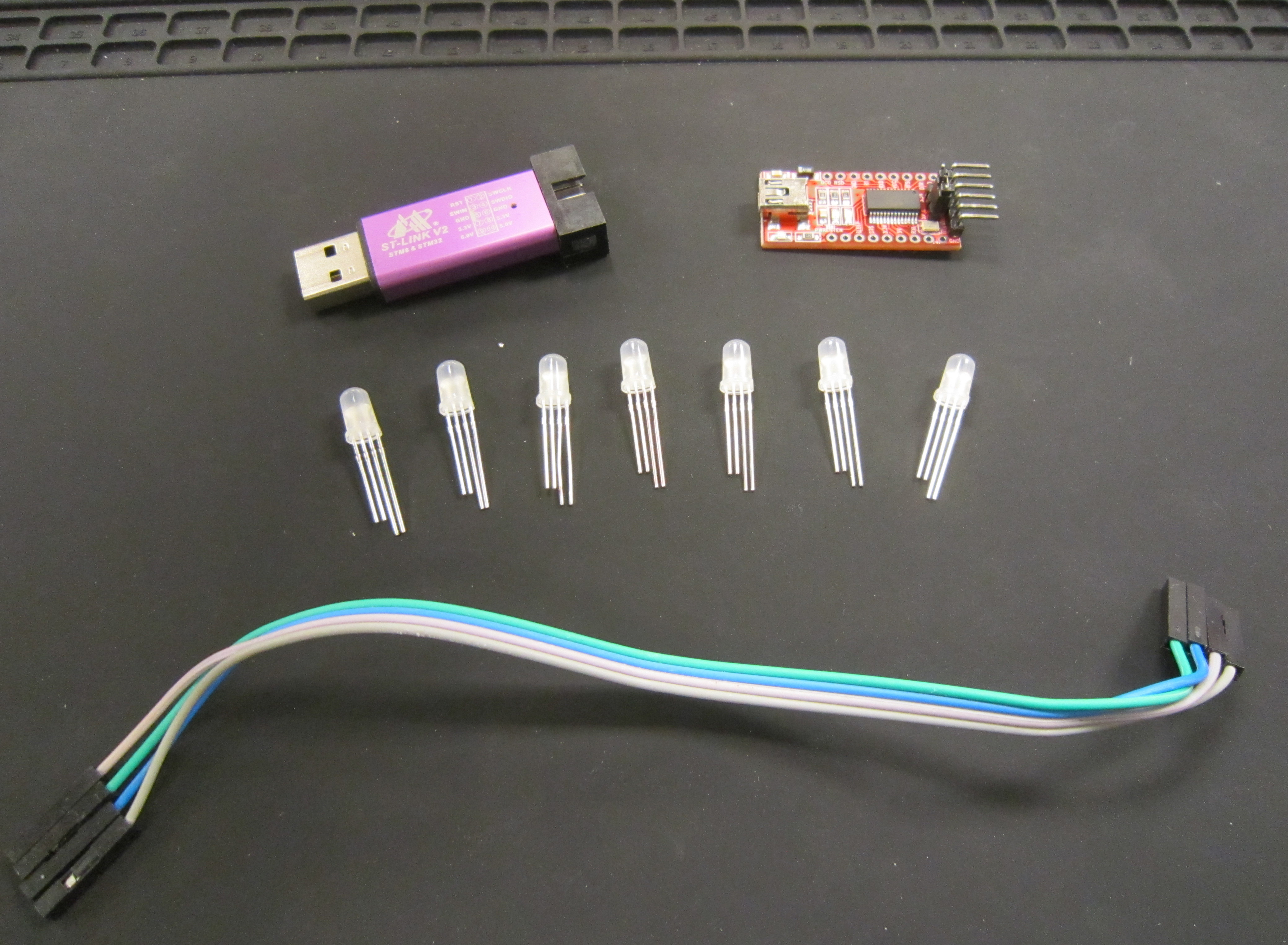
This badge was designed to be easy to solder, as well as hackable. It is based on the ARM Cortex-M4 STM32F411RET6 microcontroller, and can programmed using a ST-Link V2 programmer. Handling communications we've added a ESP-WROOM-32 with integrated bluetooth and wifi.
This year's badge is meant to be a dev kit. There are programmers available for the STM32 and ESP chips. As well as programmable LEDs which you can add to your board.
This year's badge hardware was designed by Cmdc0de, with advice help, and late night phone calls from Bunni and Krux. The firmware was developed by Cmdc0de and Gourry. Acrylic puzzle was done by Cmdc0de. Badge look and artwork, and silk screen puzzles were done by Krux.
Avoid common mistakes, and read through this guide in it's entirety before beginning. The order of assembly matters for some components in this kit.
You will need the following tools to assemble this kit
- Temperature controlled soldering station
- Fine solder, 0.032" diameter or smaller
- De-soldering pump / de-soldering braid
- Flush cut wire cutters
- Pliers
- Phillips head screwdriver
- Safety glasses
- Optional: PCB vice
- Optional: Denatured alcohol to clean the board after soldering
When soldering, it is important to always follow safe work habits. Be mindful of yourself and others. The following documents address some of the safety concerns when soldering
- Soldering Safety
- Lead Soldering Safety Guidelines
- Lead-Free_Solder_Fumes_Increase_Need_for_Fume_Extraction
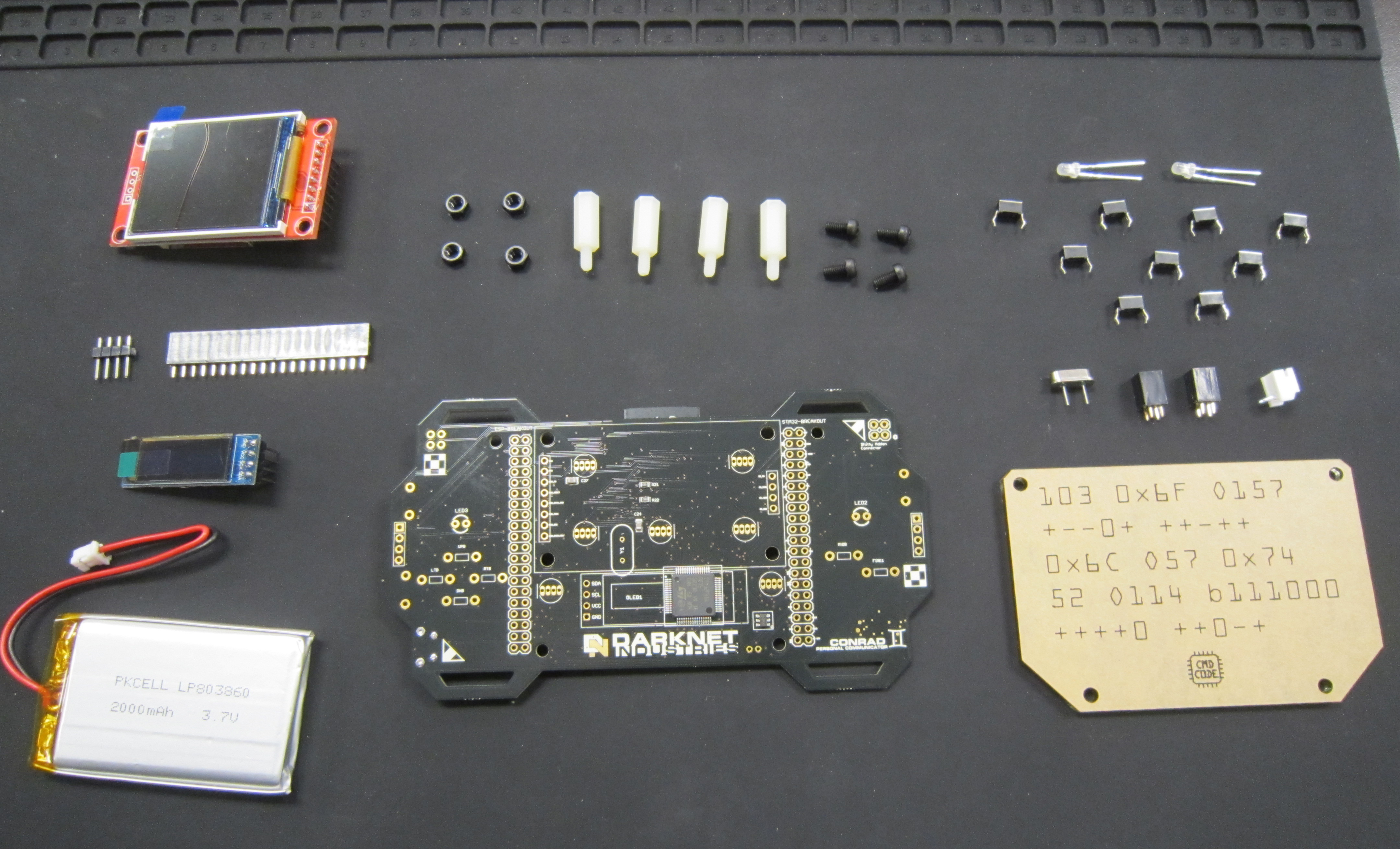
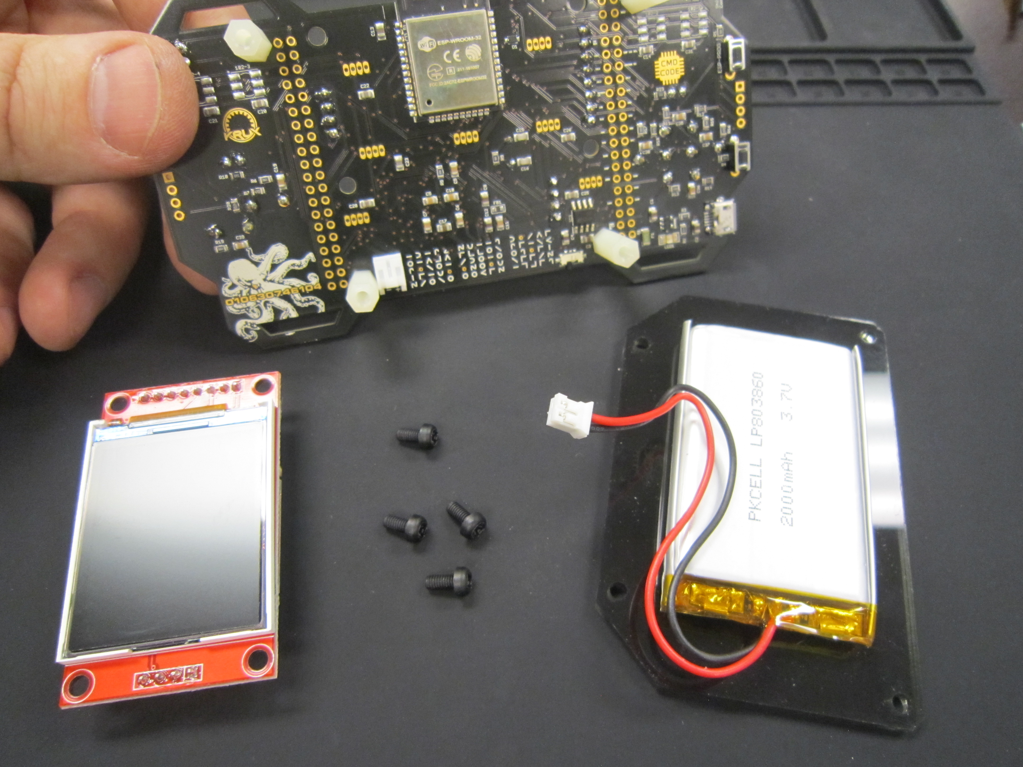
Before you get started, take a moment to ensure that all the components have been included with the kit.
Note: This is also a good time to turn on your soldering iron. For leaded solder, 320 degrees Celsius is a good working temperature.
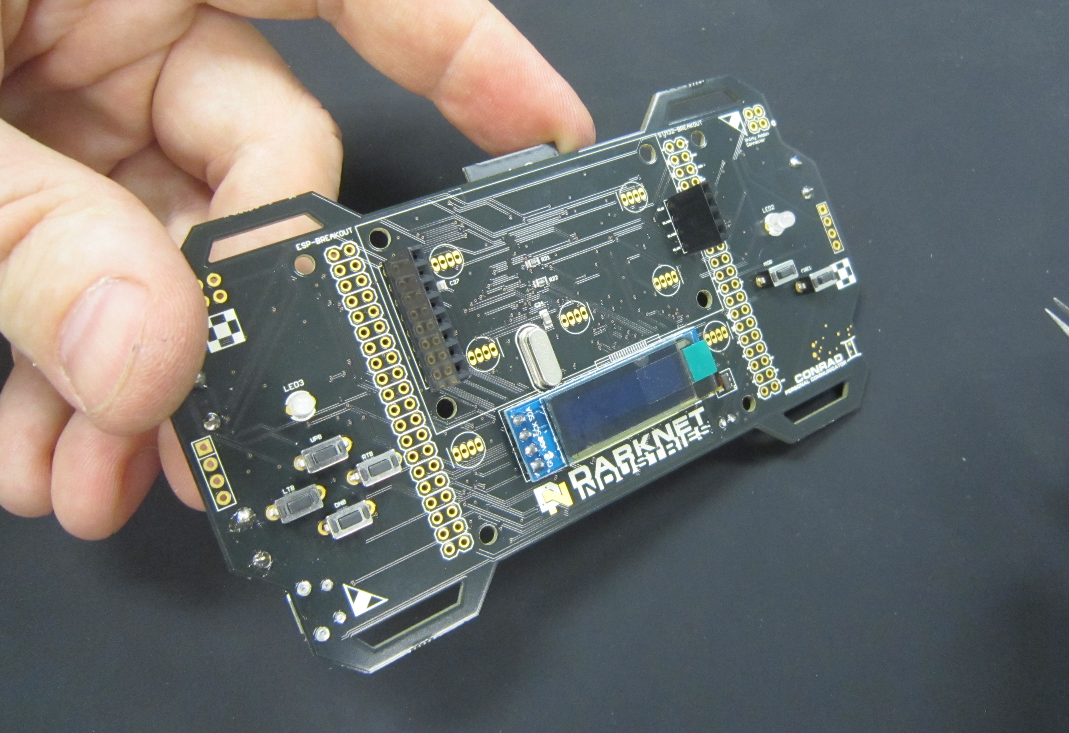
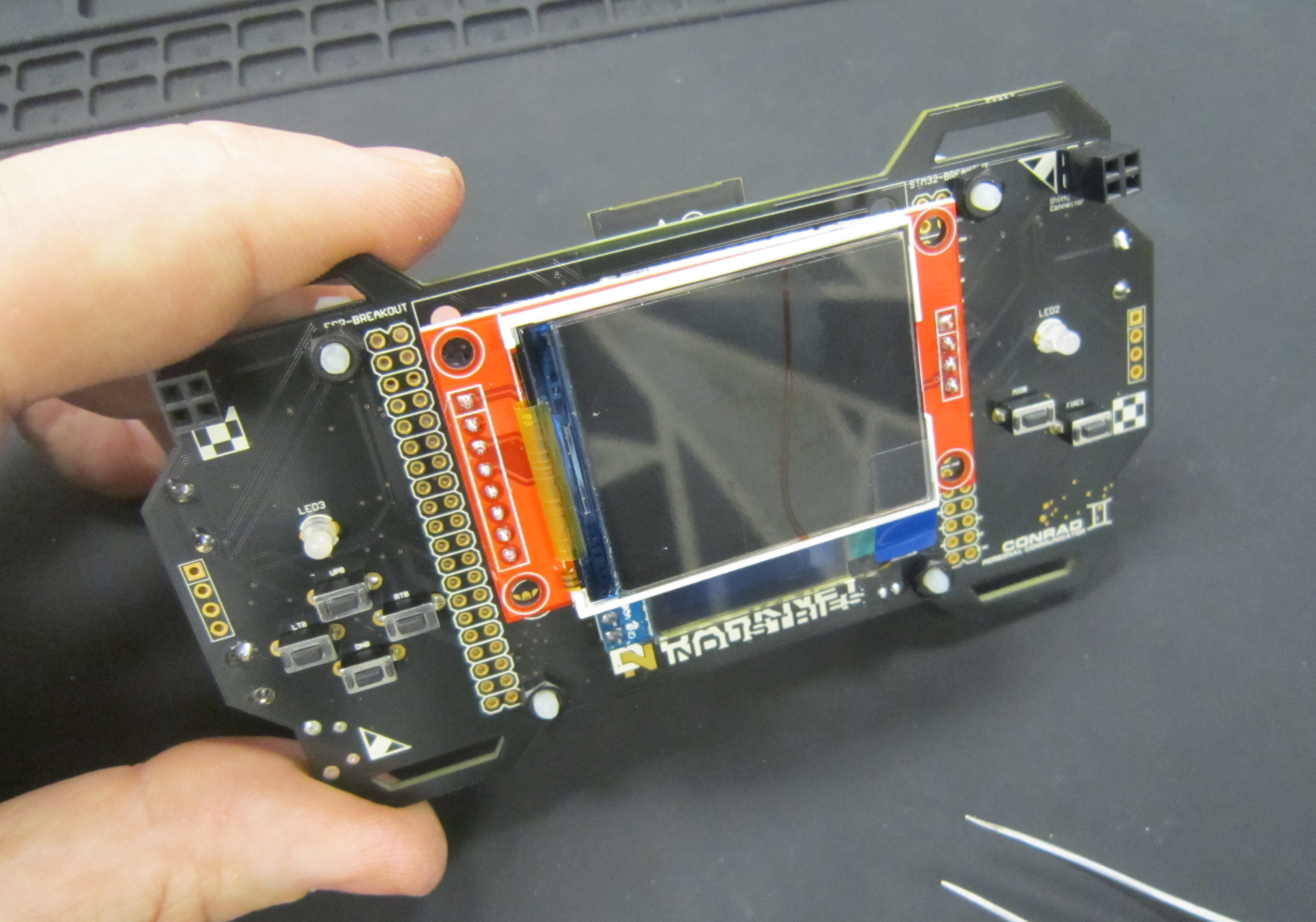
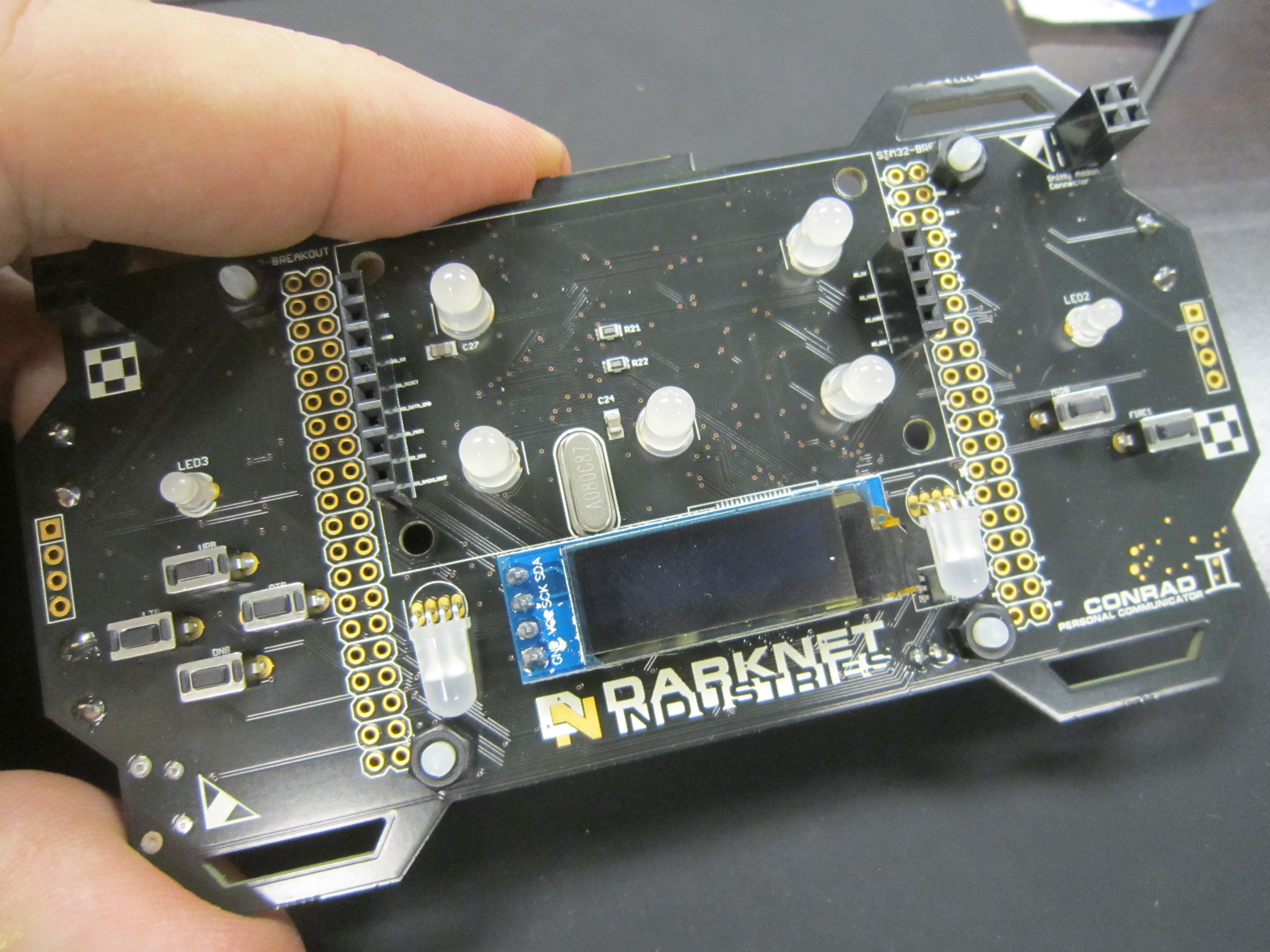
- One Darknet Industries, Conrad Personal Communicator circuit board
- One 128x32 OLED display module
- One 1.8" color LCD display module
- One four pin male header for LCD display
- One female header for LCD display
- Two 3mm LEDs
- One 8MHz crystal
- Nine Tactile Switches
- One Lipo battery
- One JST battery connector
- One acrylic backing (to tape battery to)
- Four 3mm nylon nuts
- Four 3mm nylon screws
- Four nylon standoffs
- One DarkNet Lanyard
Click on any of the images for a high-resolution version.
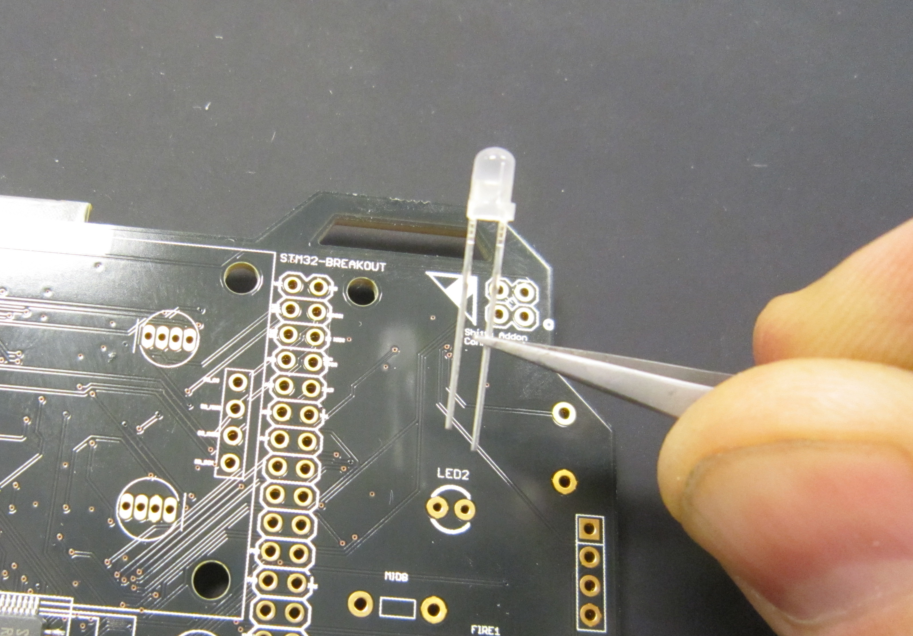
We'll start by soldering in the two standard LEDs at LED2 and LED3
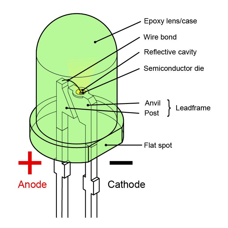
The polarity of LEDs can be determined using two methods. The leads of the LED are differing lengths, with the longer of the two leads indicating the Anode, or positive lead.
The second method is by determining the flat spot of the LED. This indicates the Cathode, or negative lead.
On the silk screen for the LEDs, it does not clearly indicated which side is the flat of the LED. Which is good, since in fact the silk screen is wrong. When looking at the front of the board, with the Darknet logo on the bottom, ensure that the cathode is toward the left as shown.
The LED should sit flush to the board as shown
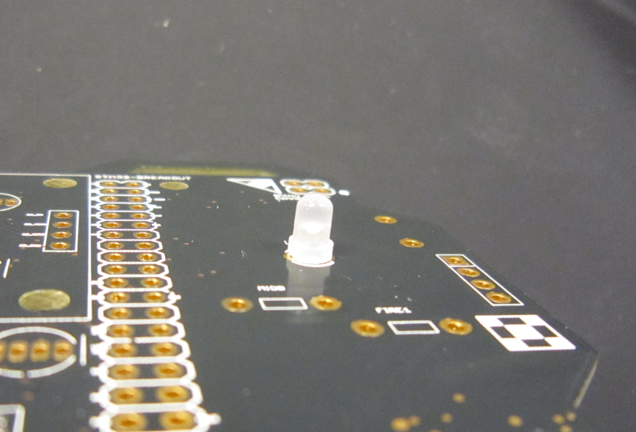
To aid in soldering, and to help keep the components in place, the leads may be splayed at a slight angle to hold the parts in place. Double check that the parts are still flush with the PCB before soldering.
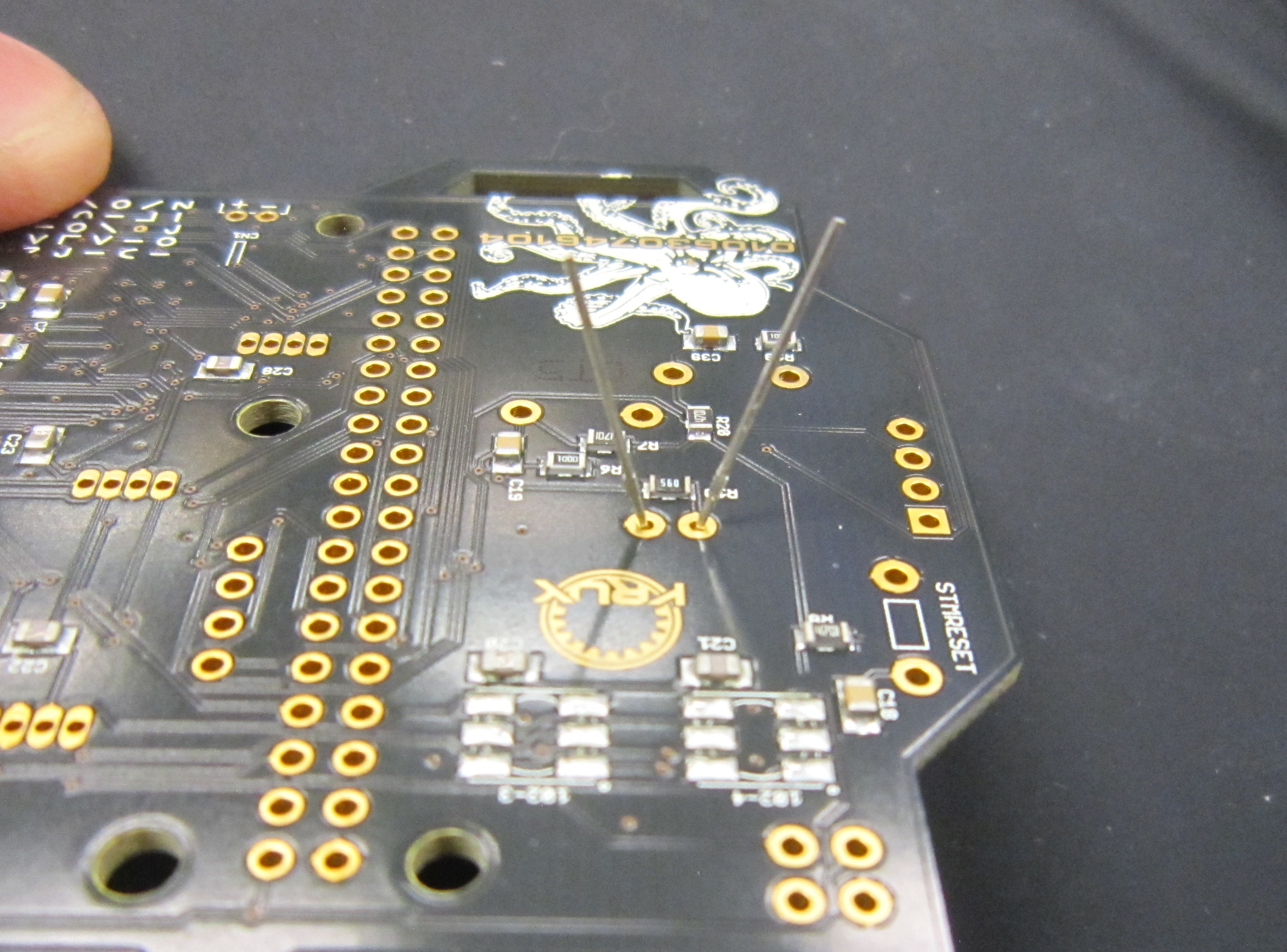
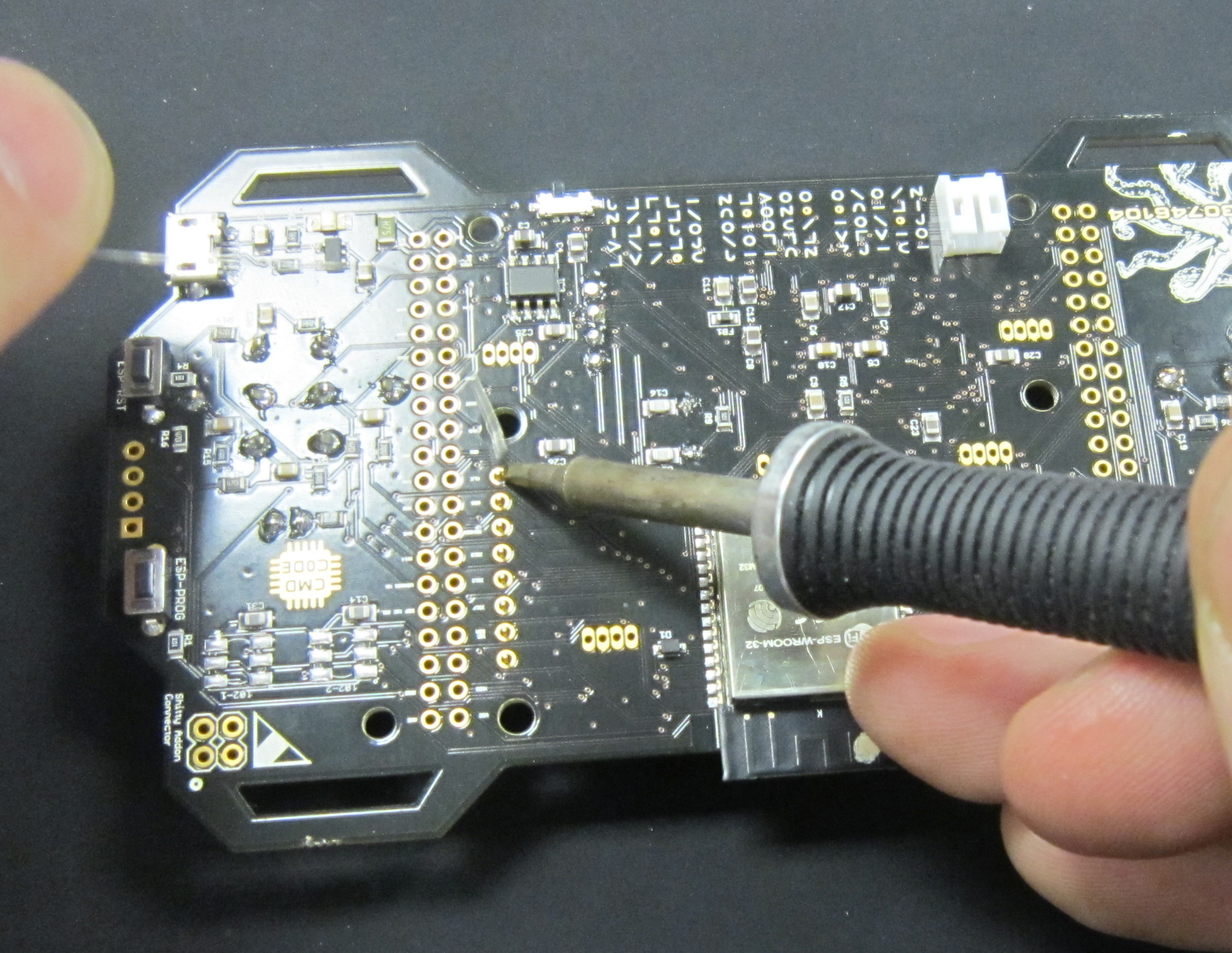
Ensure the tip of your soldering iron is always kept clean. It should be shiny in appearance. Removing the oxidation by wiping the soldering iron on a solder sponge.
When using a chisel tip as show, the flat of the tip can be used. When using a conical tip, use the section of the iron just to the side of the tip. This gives you a larger area of thermal contact and will make soldering easier.
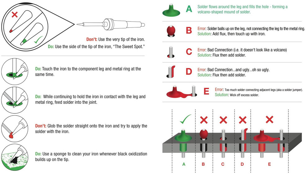
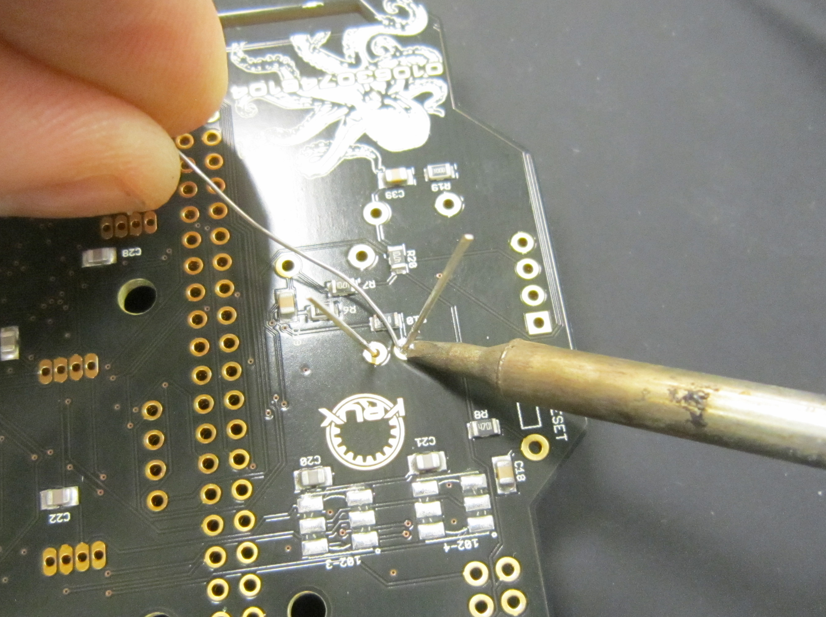
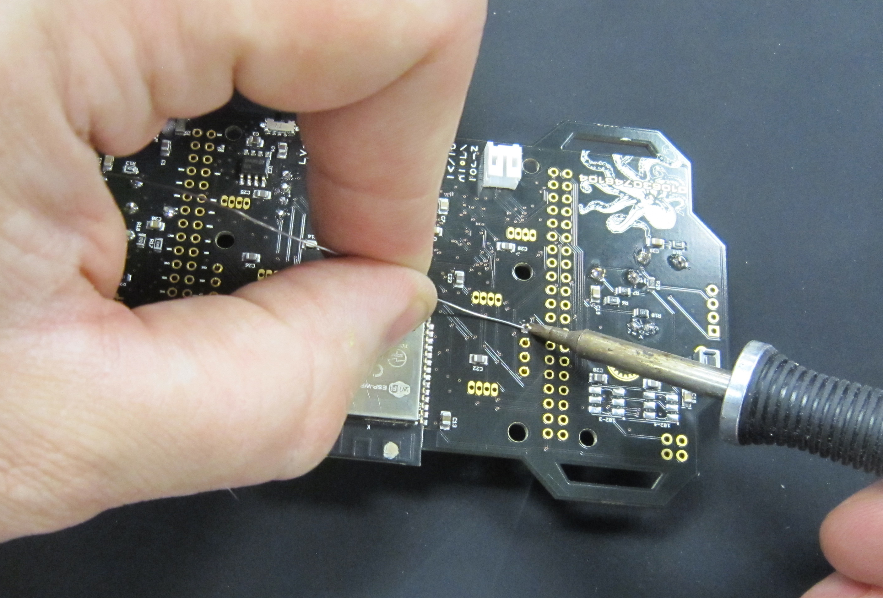
Begin soldering by positioning the tip of the iron so that it makes firm contact with both the solder pad on the PCB and the lead of the component. This ensures that both the pad and the part both get sufficiently hot so that they are able to melt the solder and make a good electrical connection. Feed solder in sparingly on the side opposite the soldering iron. The solder should flow on the solder pad and lead of the component, forming a conical shape.
The following diagram shows more details on soldering DOs and DON'Ts
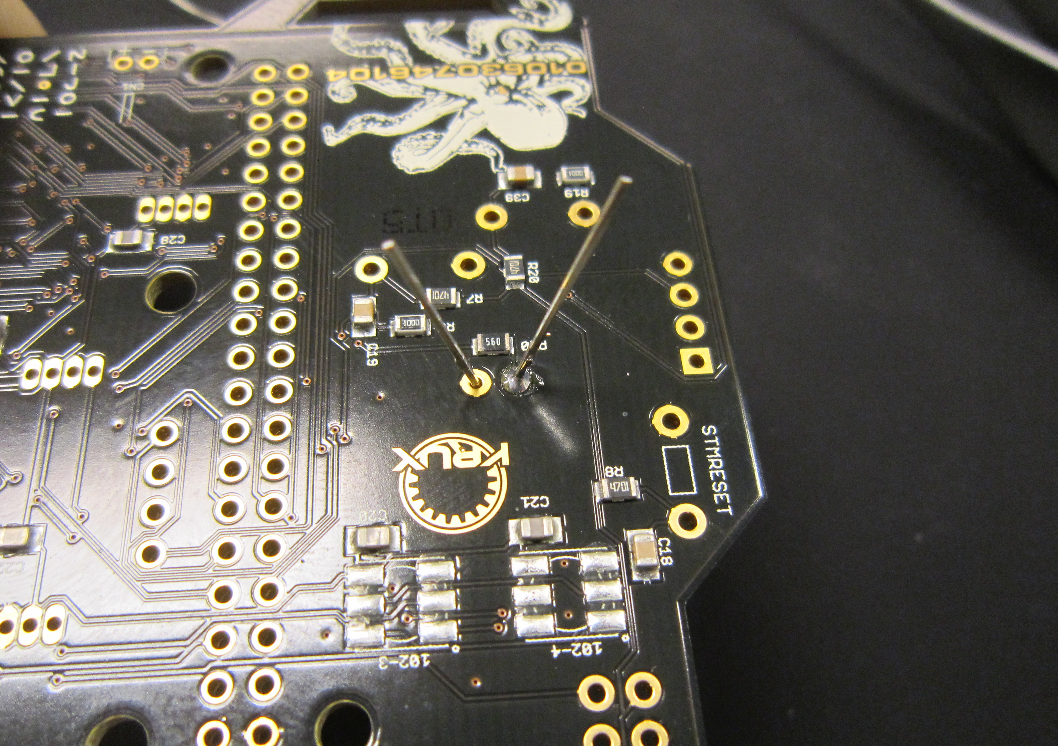
Solder both LEDs in place.
You should have a nice cone of solder that covers the pad, and smoothly transitions the component lead.
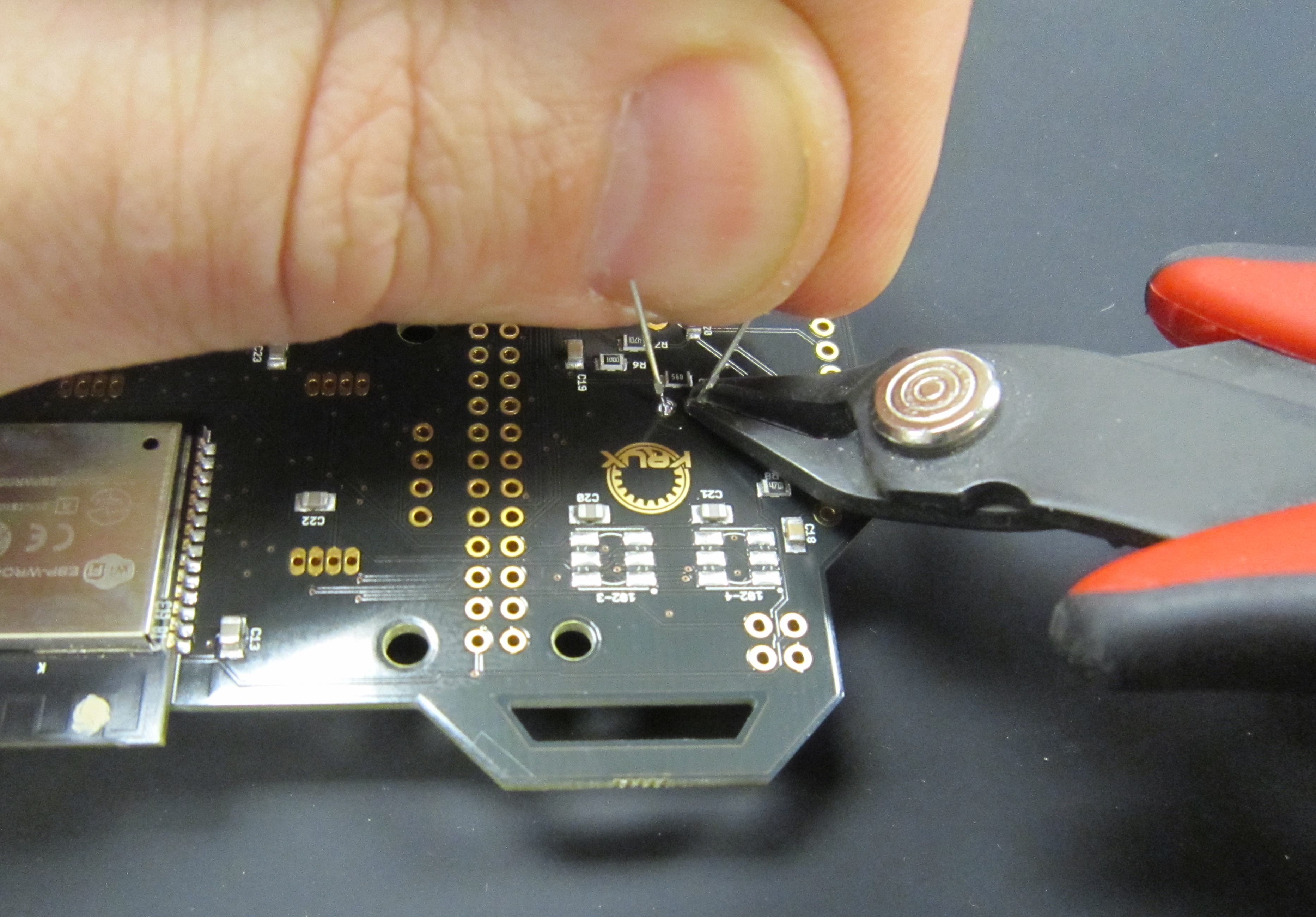
Using flush cutters, trim the resistor leads close to the board. This should be where the component lead meets the solder, as shown here. Excess lead can make unintentional contact with other components and cause shorts, so leads should always be trimmed as close to the board without cutting away the solder joint.
Safety Tip: When cutting component leads, ensure that you are holding the lead when you cut the part to prevent the lead from becoming a projectile. Not doing this can lead to eye injury for yourself or others. You can easily do this by holding a finger tip over the lead as you cut it.
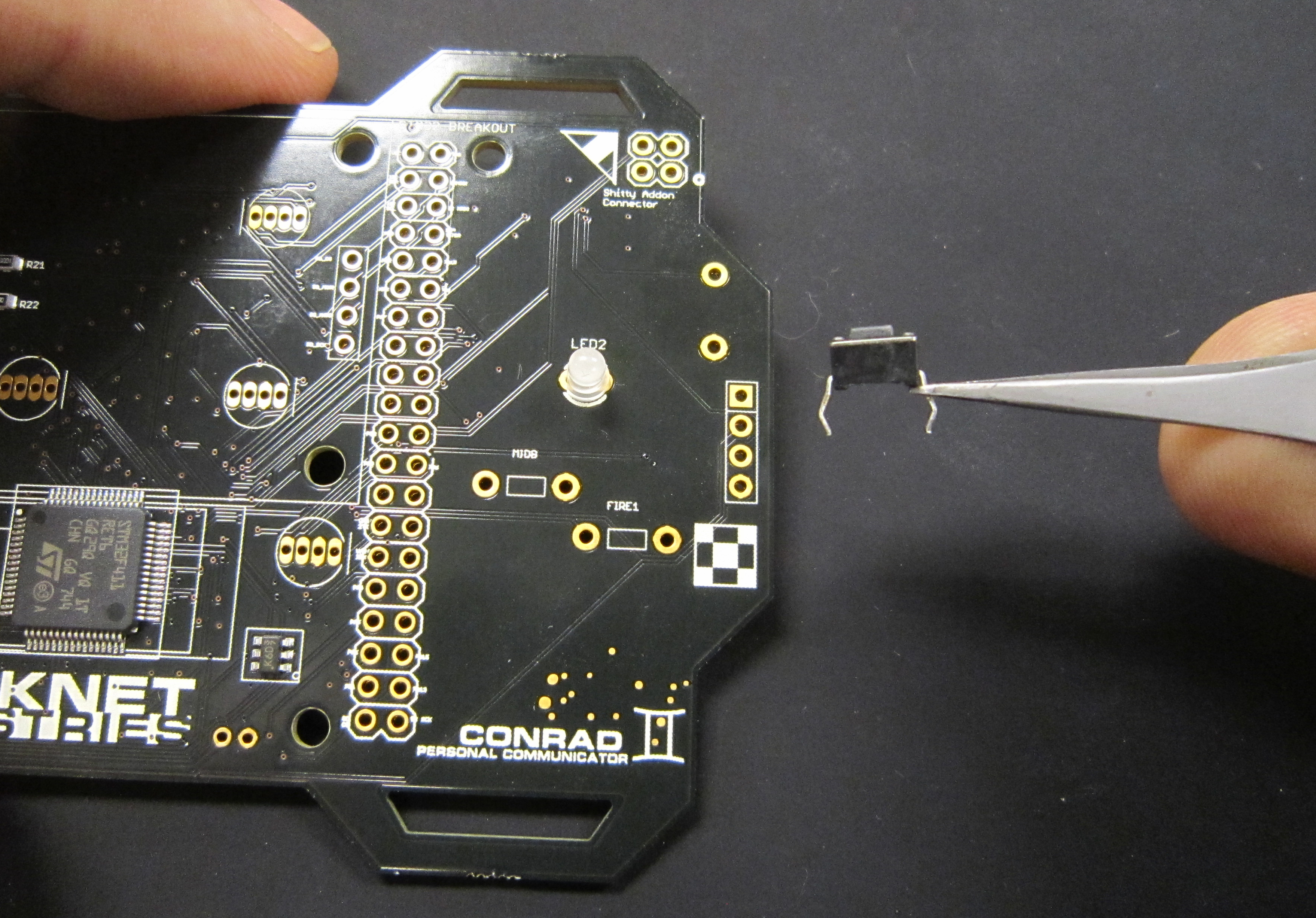
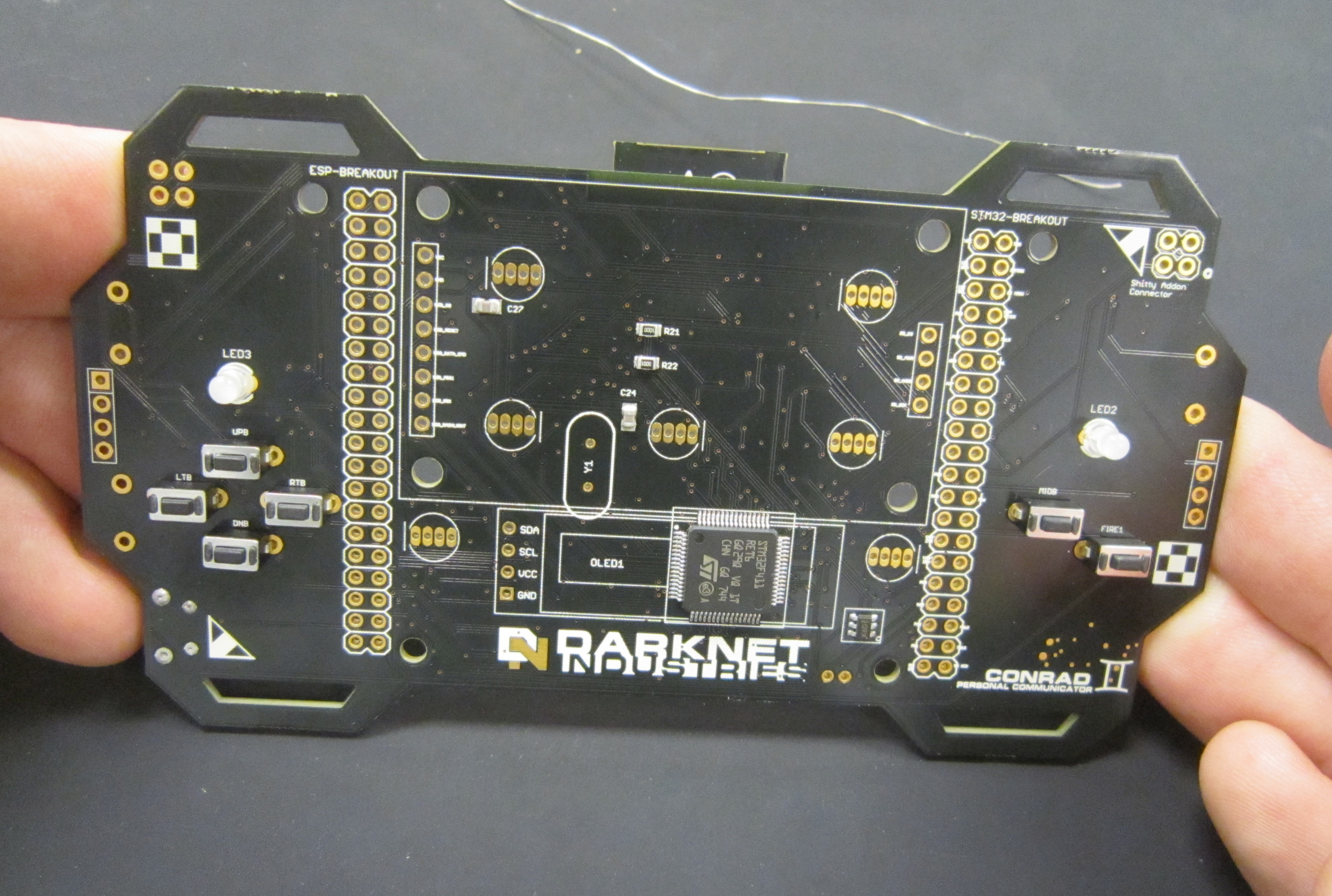
Next well solder in the six switches on the front of the badge, for the directional control, mid, and fire buttons.
Populate the parts, and solder into place. The component leads will snap into place and hold the part while soldering.
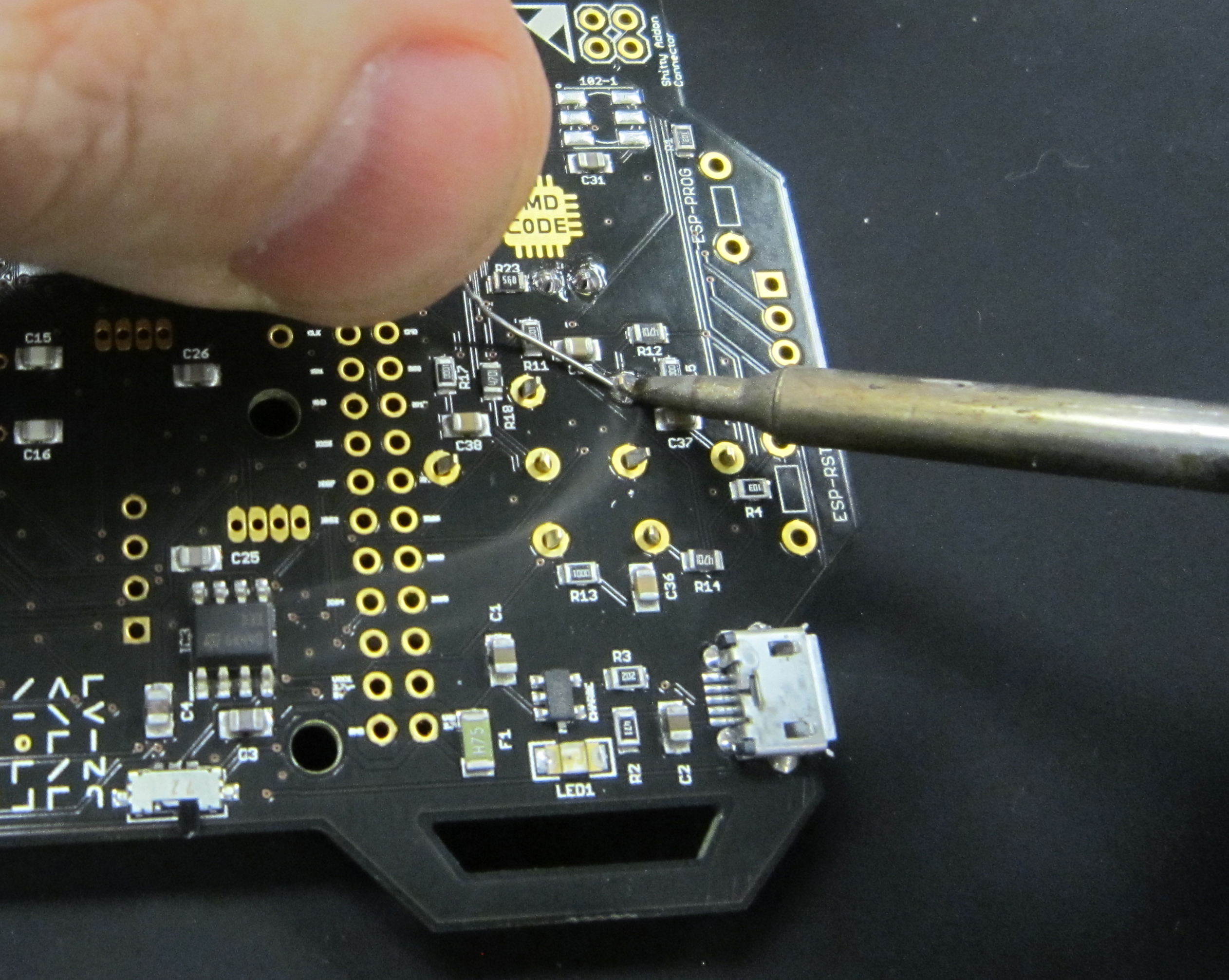
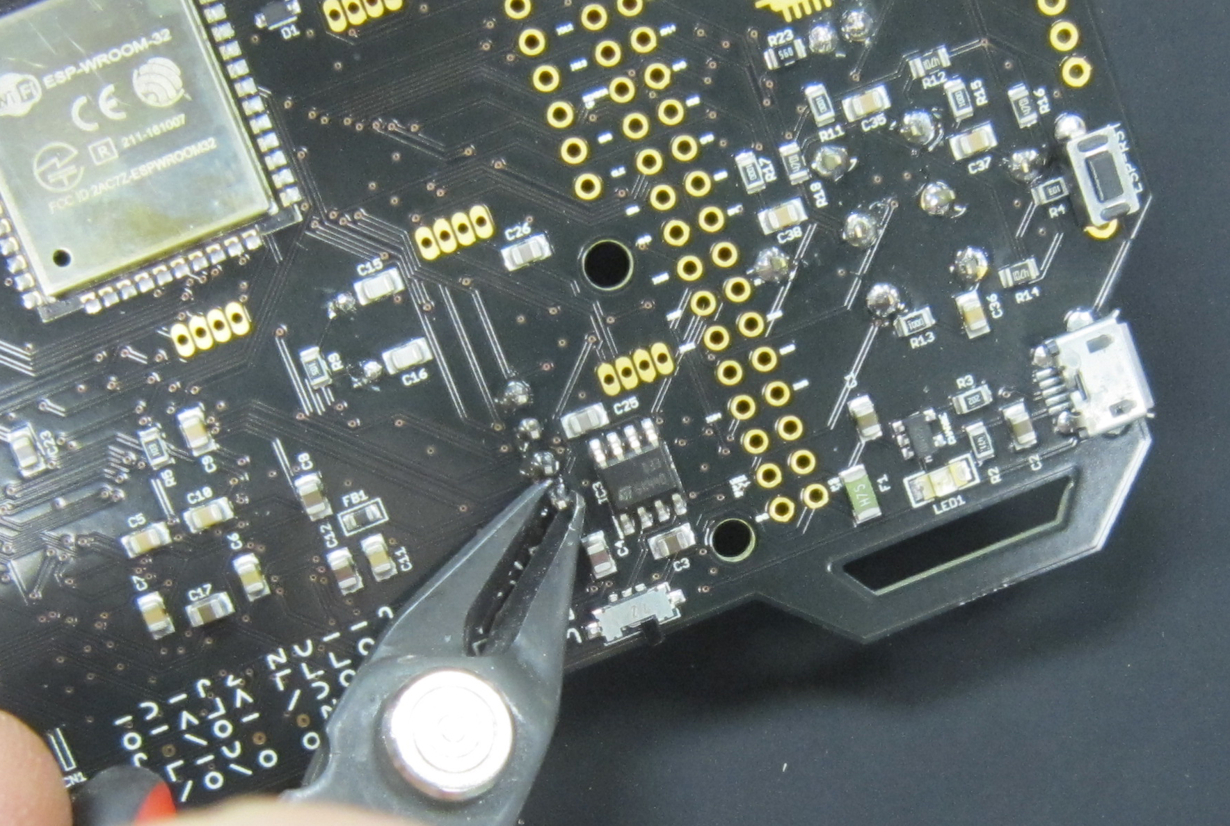
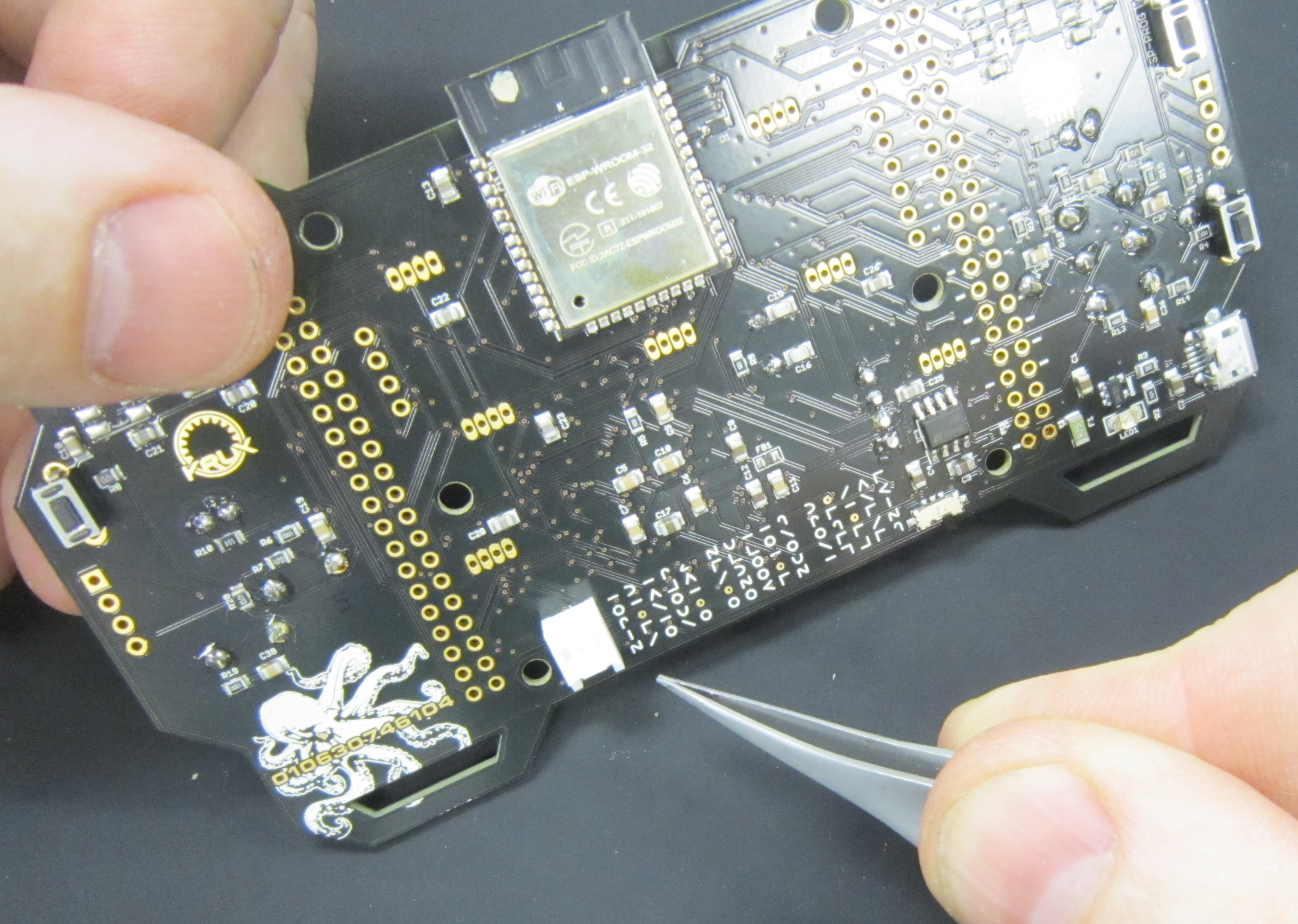
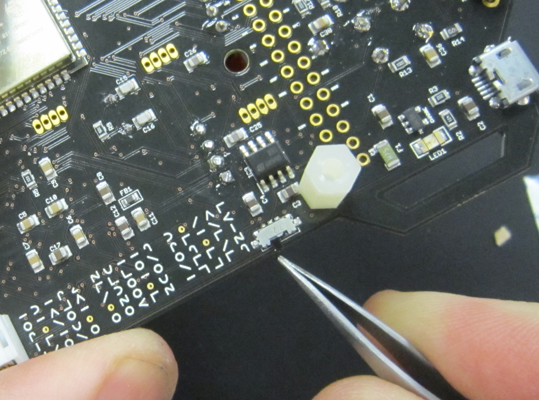
Next, solder the switches for ESP-PROG, ESP-RST, and STM RESET. These switches go on the bottom side of the board.
Note: If desired you can choose to instead solder the switches for programming and reset to the top side of the board.
Next add the 8MHz crystal to the board at Y1
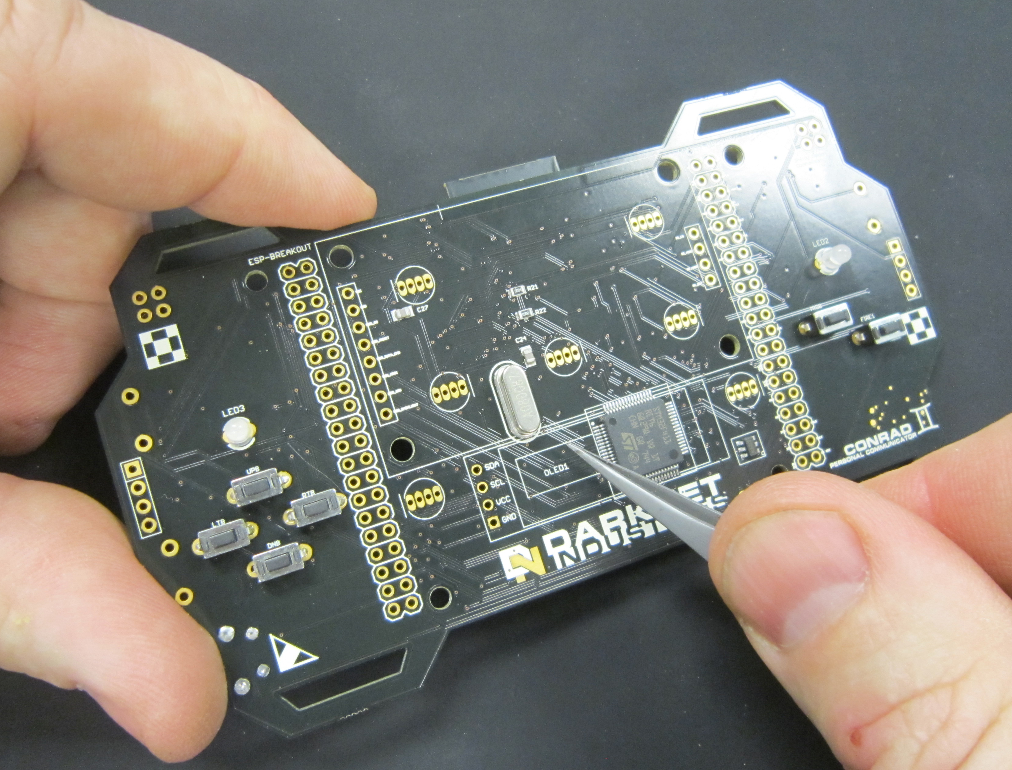
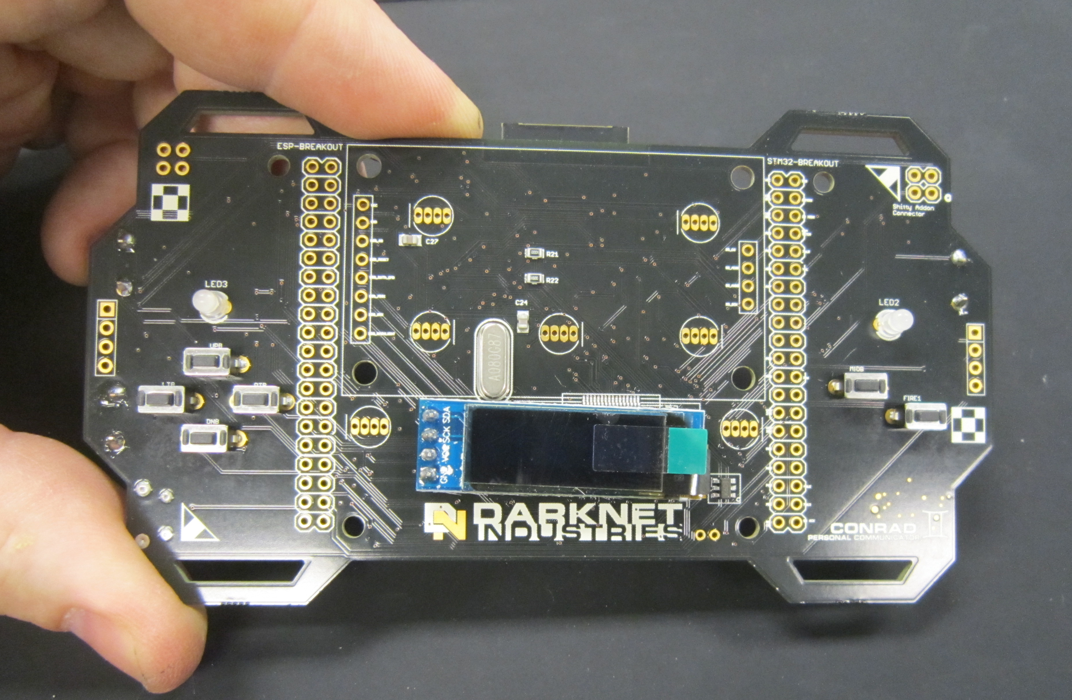
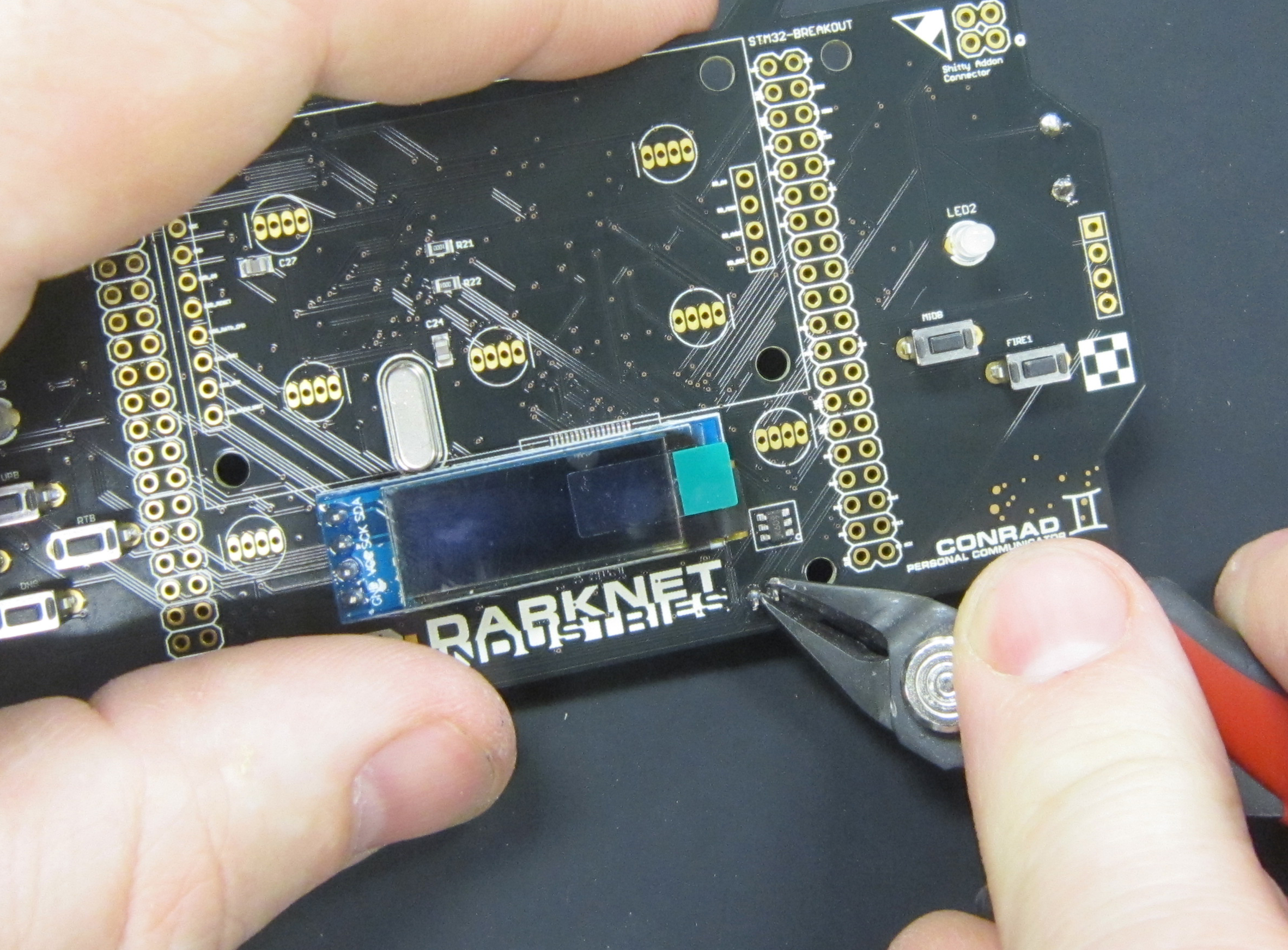
Next we'll be adding the OLED display, which is driven from the ESP 32.
After soldering, trim the leads on the under side of the board.
 While trimming headers does flare the pins, which makes future
rework more difficult, we need to trim the pins to prevent accidentally damaging the battery.
While trimming headers does flare the pins, which makes future
rework more difficult, we need to trim the pins to prevent accidentally damaging the battery.
Now solder in the JST connector for the battery.
Trim the leads after soldering to prevent them from accidentally shorting with one another.
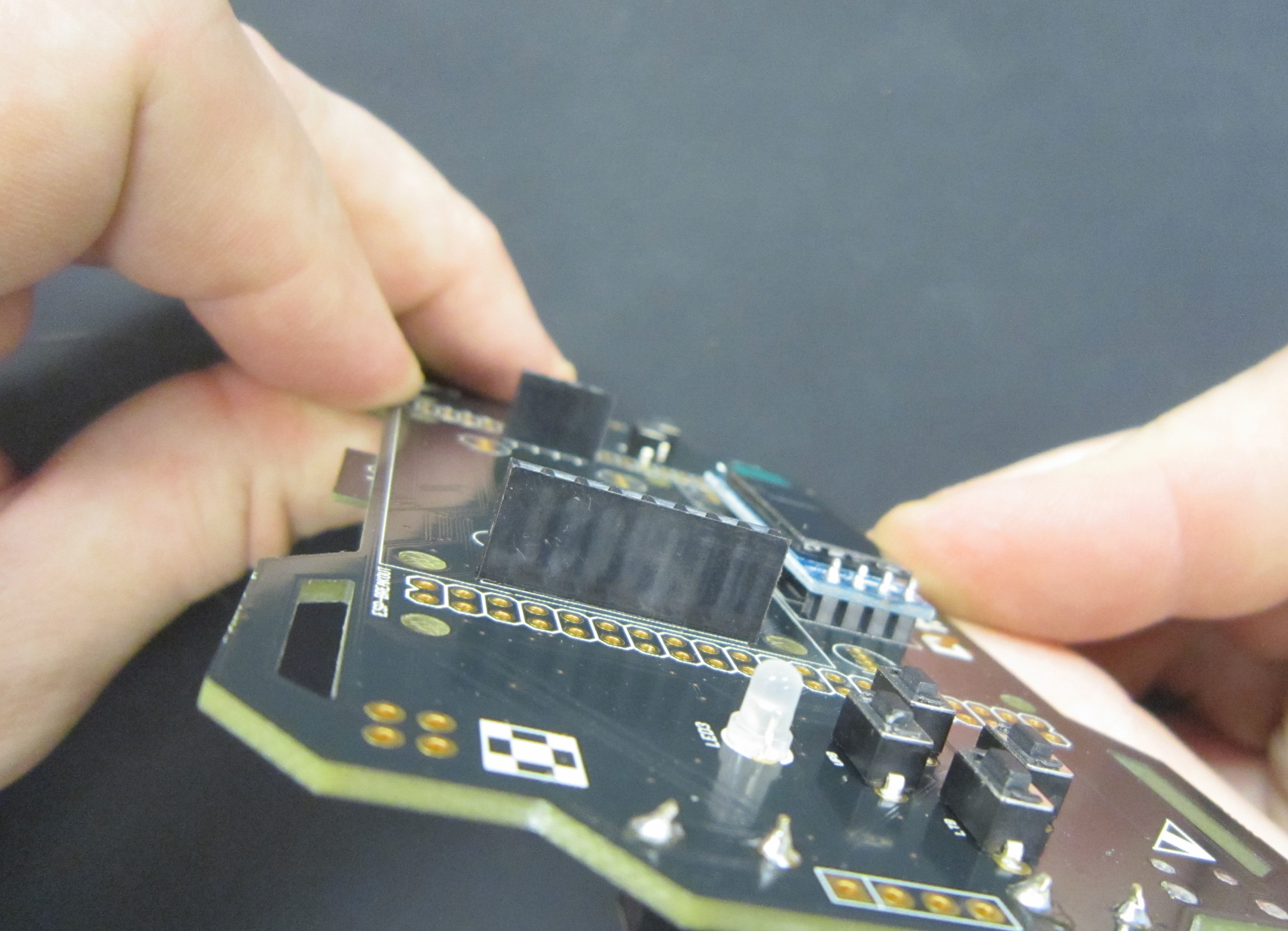
The LCD display, driven by the STM32, is attached to the board using female headers. This gives clearance for, as well as allows removing the display for the installation of the programmable LEDs.
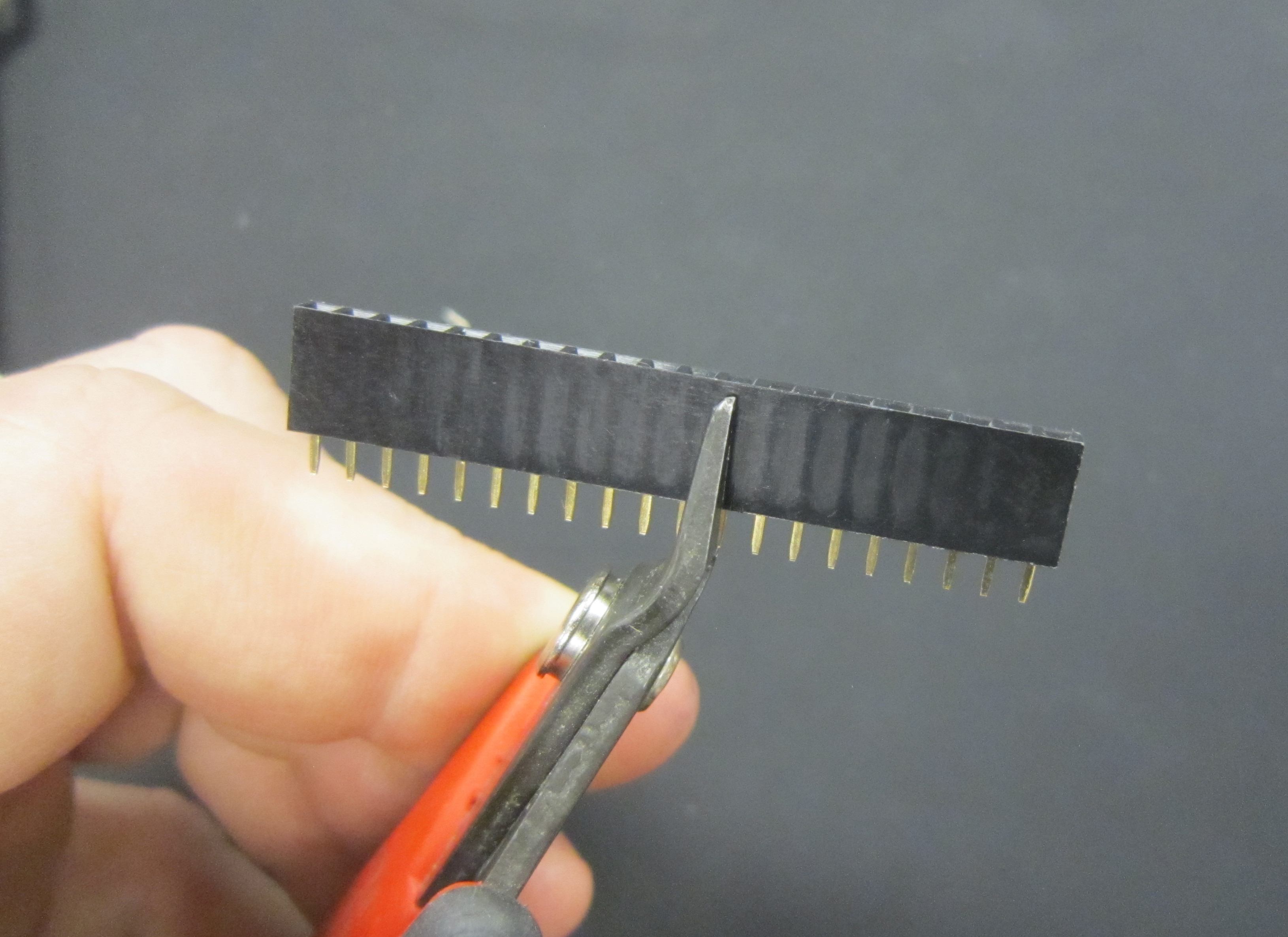
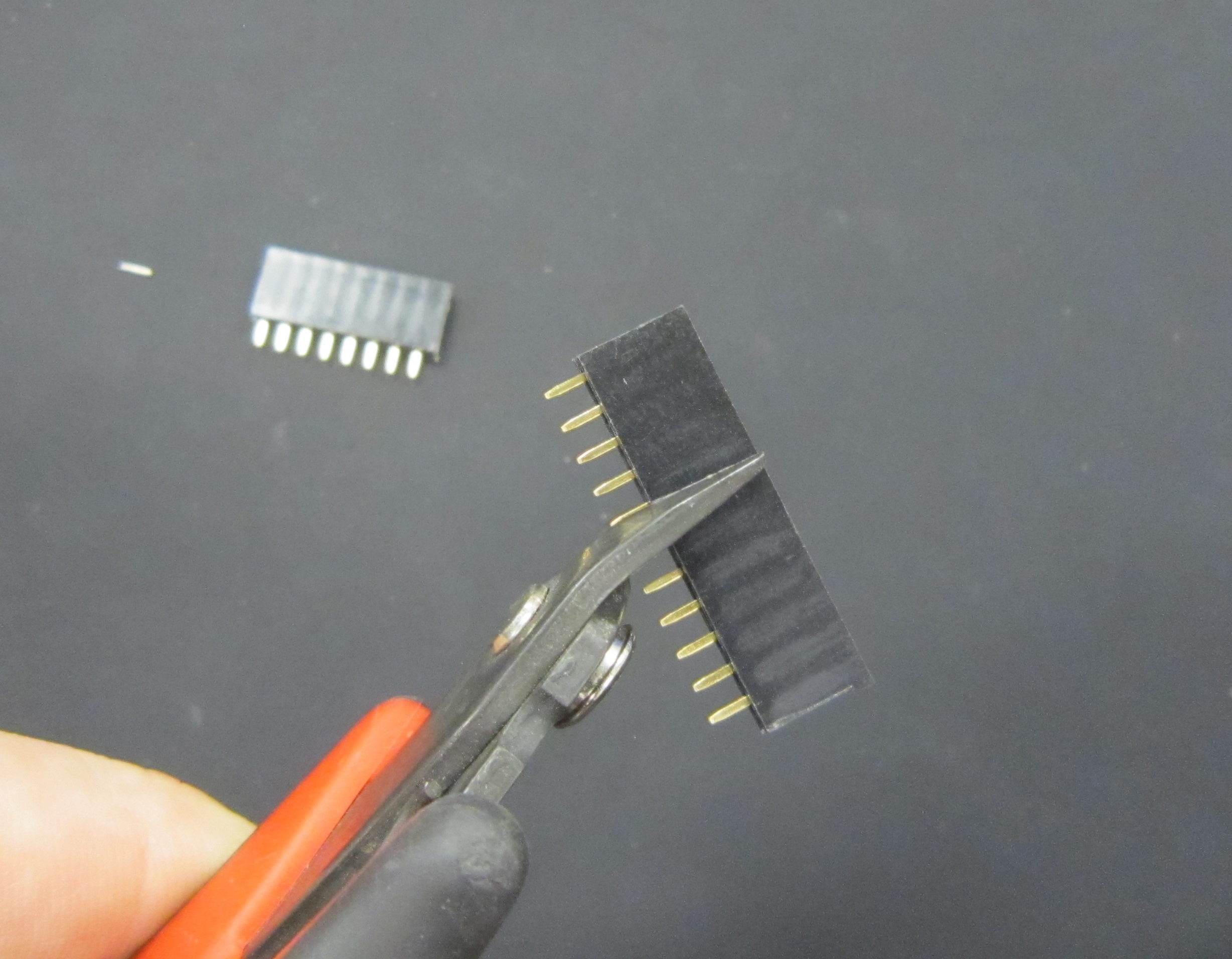
We'll start by cutting the provided female header for the 8 pin side of the display. When cutting female headers, you always have one sacrificial pin which is lost at the cut, as it's not possible to cut between two pins as you can with male headers. So count out eight pins, and cut on the nineth pin.
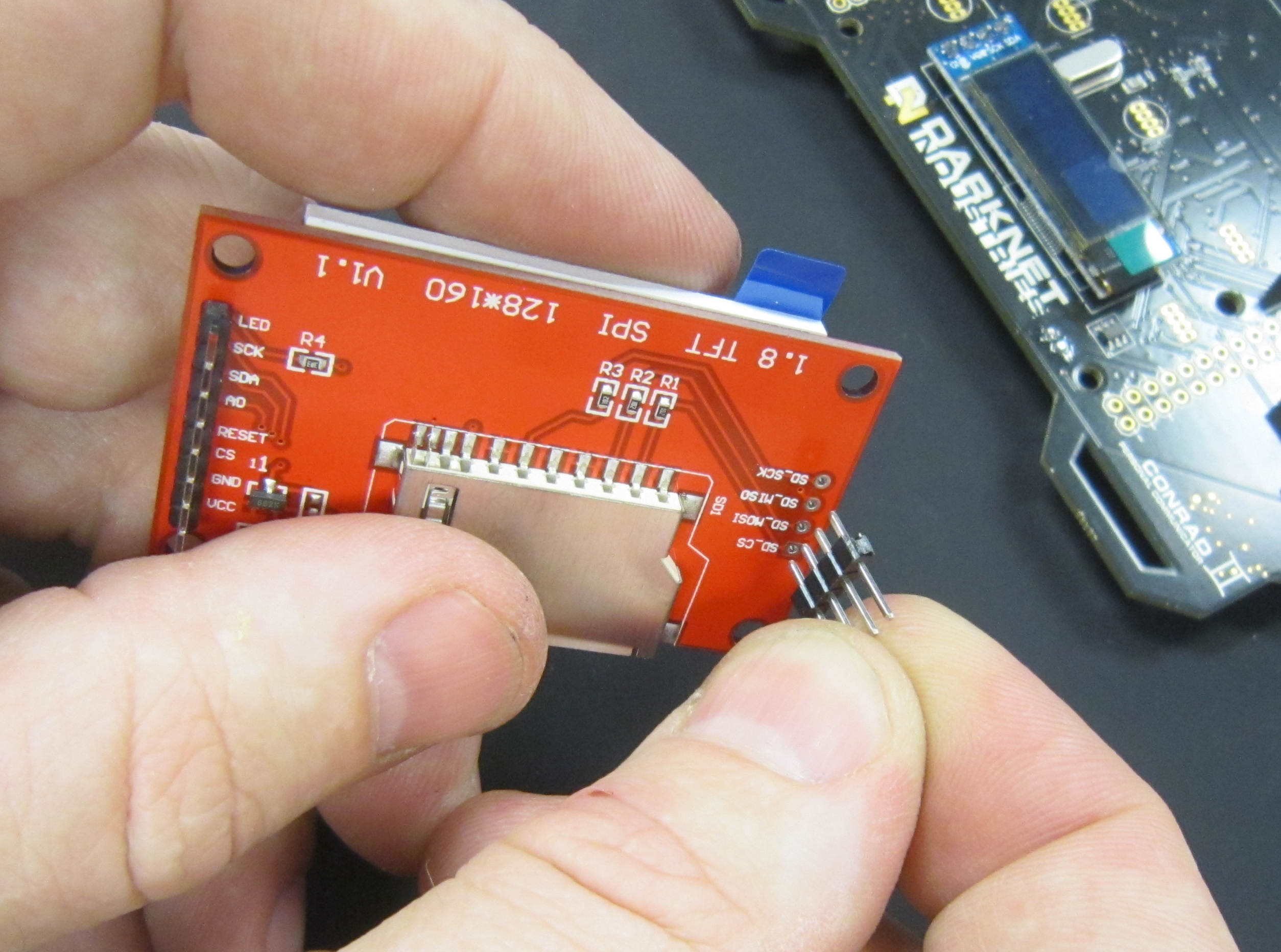
Next we need a four pin header for the other side of the display. So count out four pins, and cut on the fifth pin.
Install the headers.
To solder, you can set them on a flat surface to ensure they are square to the badge when soldering.
Solder one pin on each header. You can use a finger to steady the board while soldering.
Verify that your headers are flush with the board, and then finish soldering the remaining pins.
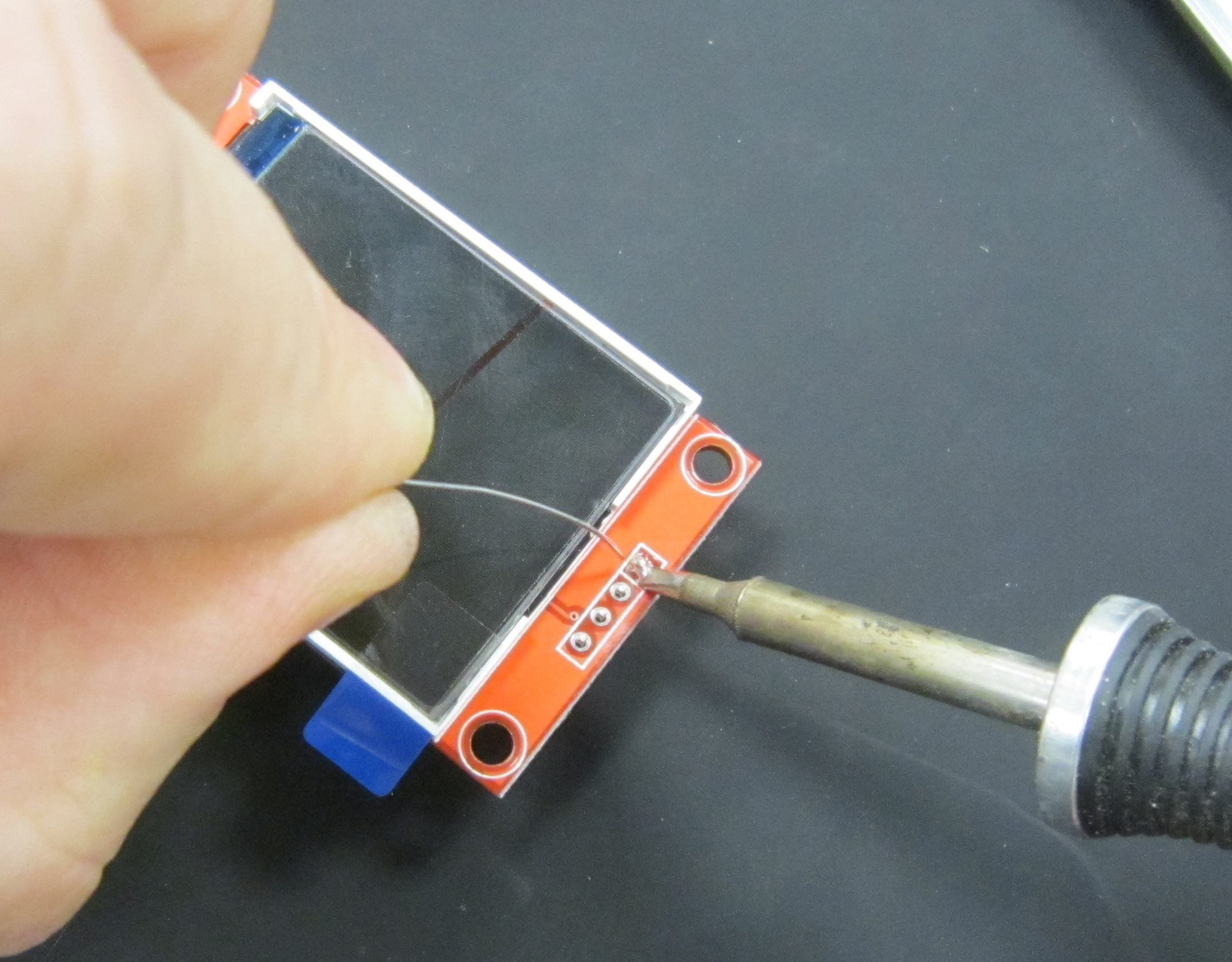
Next we'll be adding the four pin male header to the LCD display
Again, use the same trick of soldering on a flat surface to make sure the header is straight. Solder one pin, check that it is square, and solder the remaining pins.
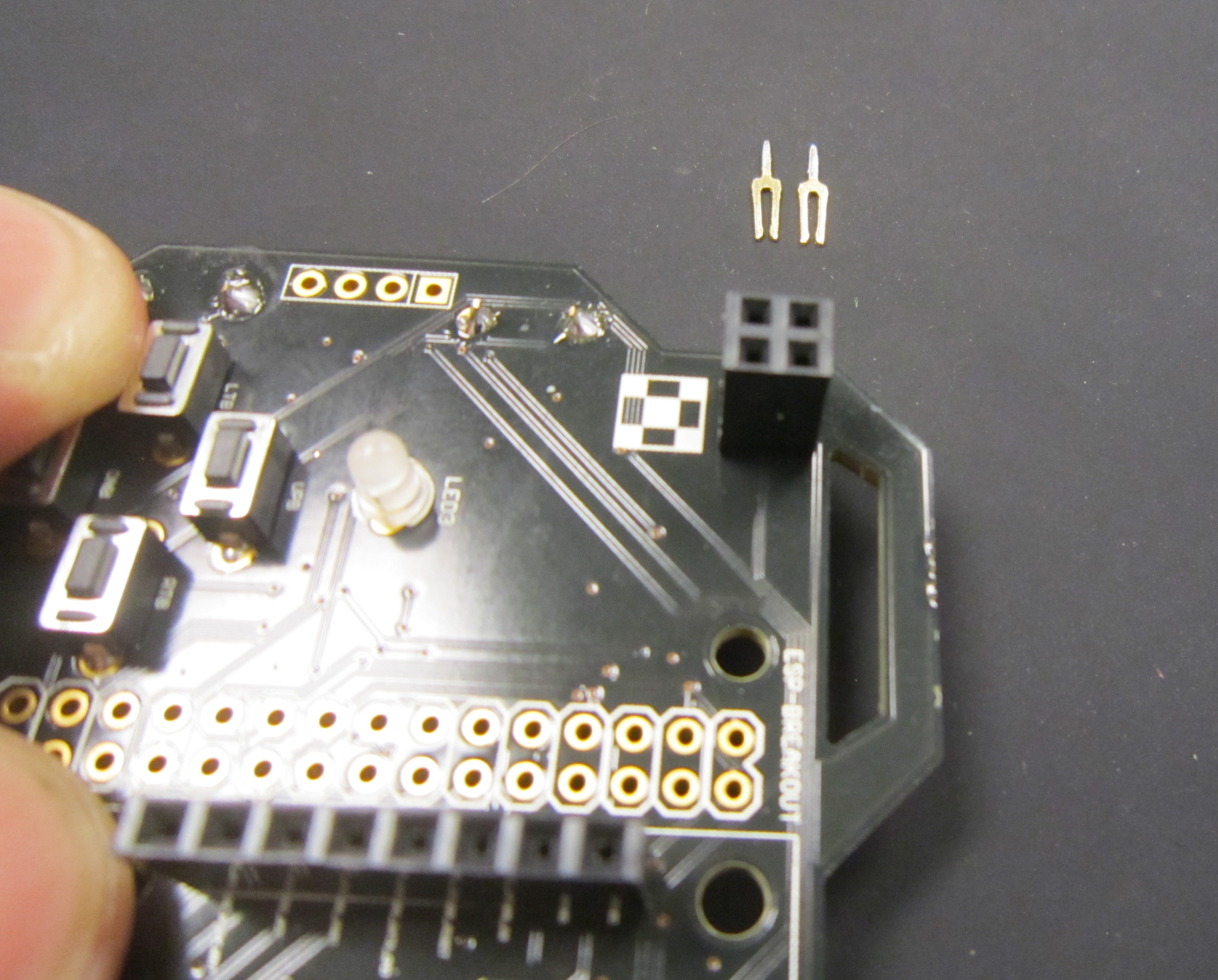
This year's badge has two Shitty Add-on headers. This is a standard that Brian Benchoff in the badge maker community slaved over, taking at least three minutes in MS Paint to well document everything you need to know about making your own add-ons.
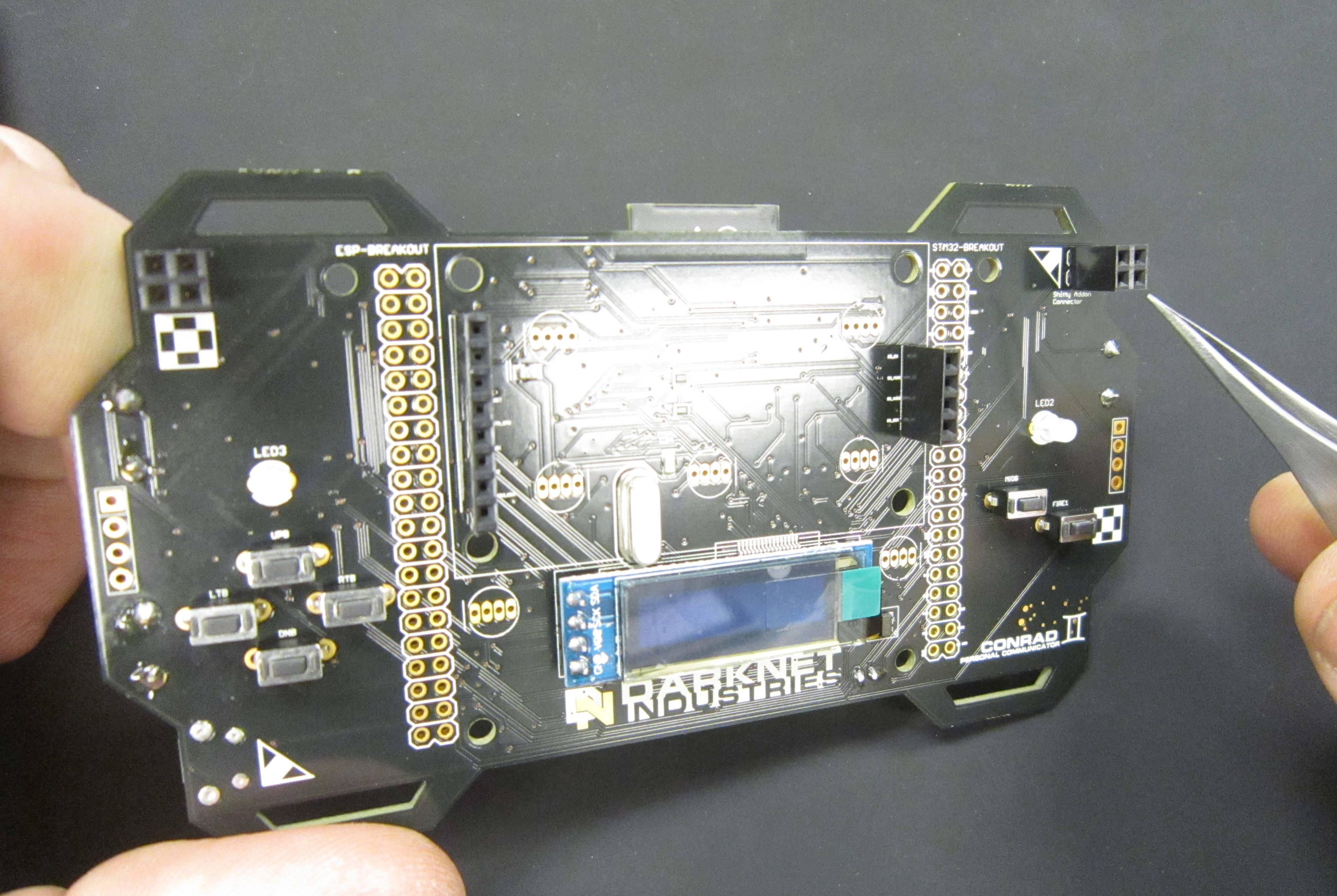
We opted to hedge our bets, as to how this is interpreted, and give you a normal SAO connector on the right, and a mirrored SAO connector on the left. Our own SAO, the Eggplant SAO makes use of the connector on the left. Which means technically it's wrong... but whatever.. it's a shitty standard. :)
However to try and keep your add-ons from falling onto the ground, you'll want to keep in mind how female pin headers are constructed. As it's just a blade that contacts the male pins in the header, there is more play side to side than in line with the blade.
Soldering the connectors in so the blades are vertically aligned, should make the SAOs slightly more secure. Though you will still want to be mindful that your SAOs do not get lost.
This kit uses a pieces of acrylic which acts as the battery holder for the Lipo battery. It both protects the battery, but also ensures that you are able to remove the battery from the badge if needed. Such as hacking to the badge to do new and interesting things.
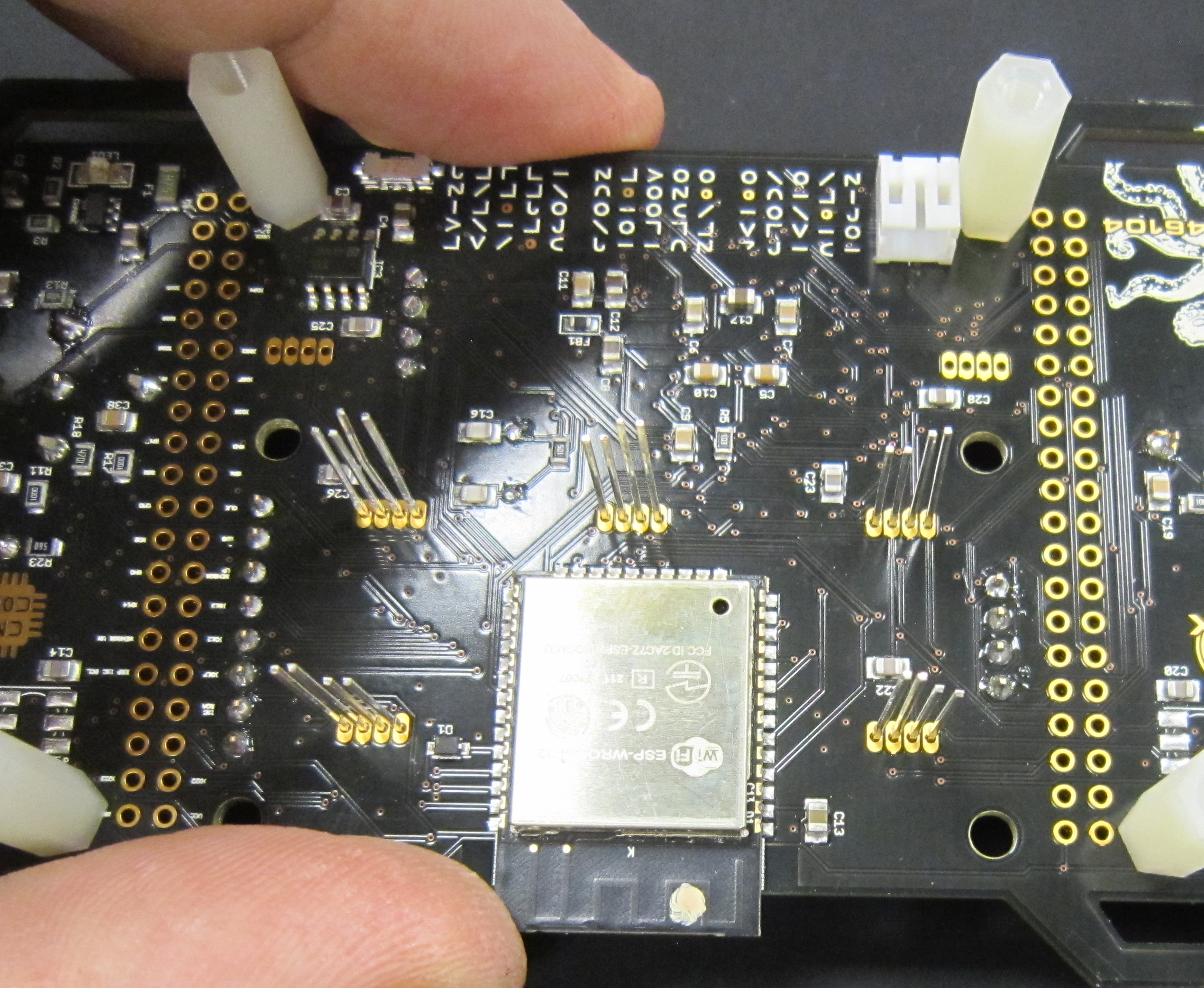
Install the nylon standoffs as shown
Using the provided 3mm nuts and stand offs, install so that the nut is on the front of the badge as shown.
Next we'll be installing the acrylic backplate which is our battery holder.
Pro-tip: To avoid getting the glue from the backing on the acrylic, use a finger nail to remove the inside of all letters and numbers which have a center bit, such as A, 0, 4, e, 8, 6, 9, P, etc..
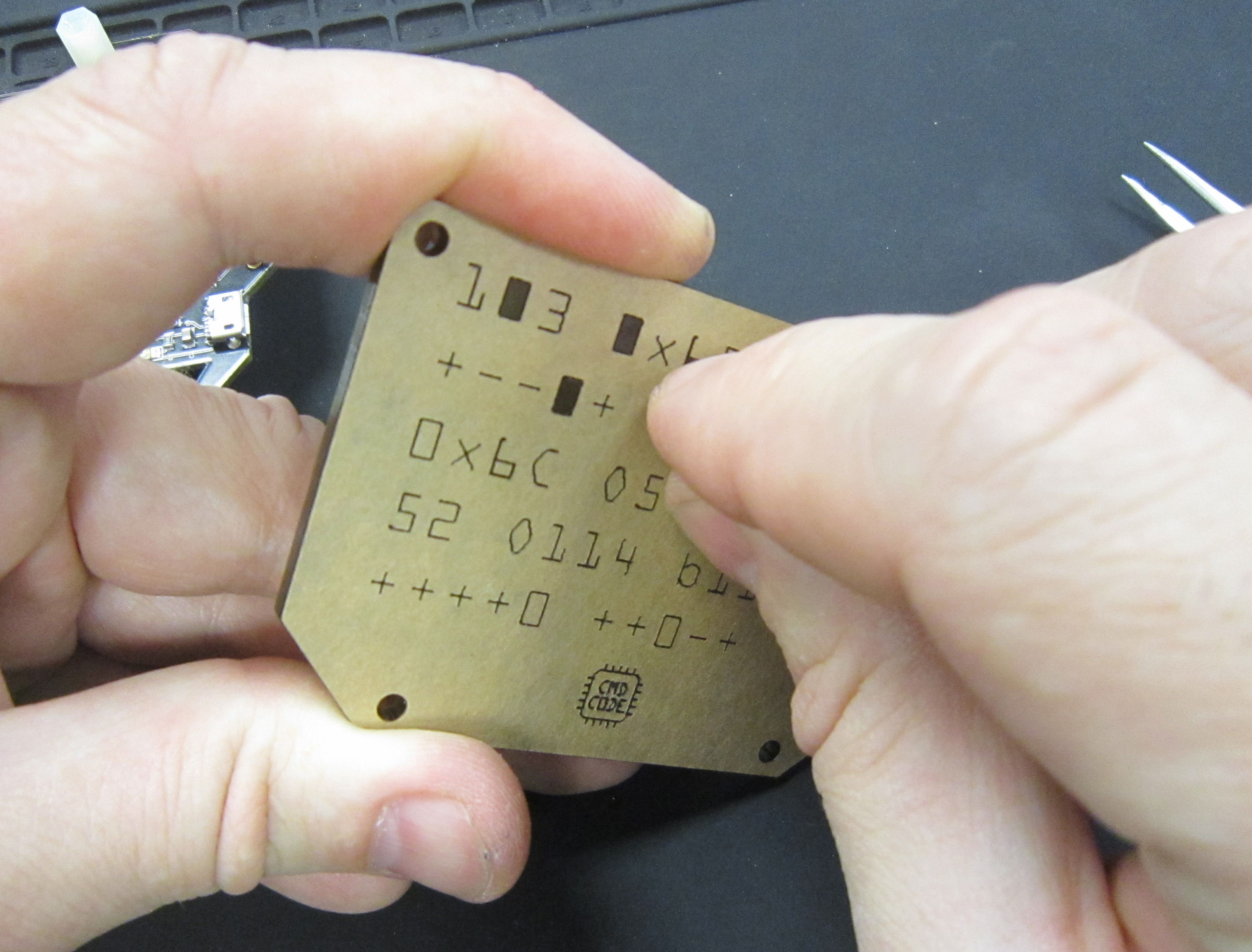
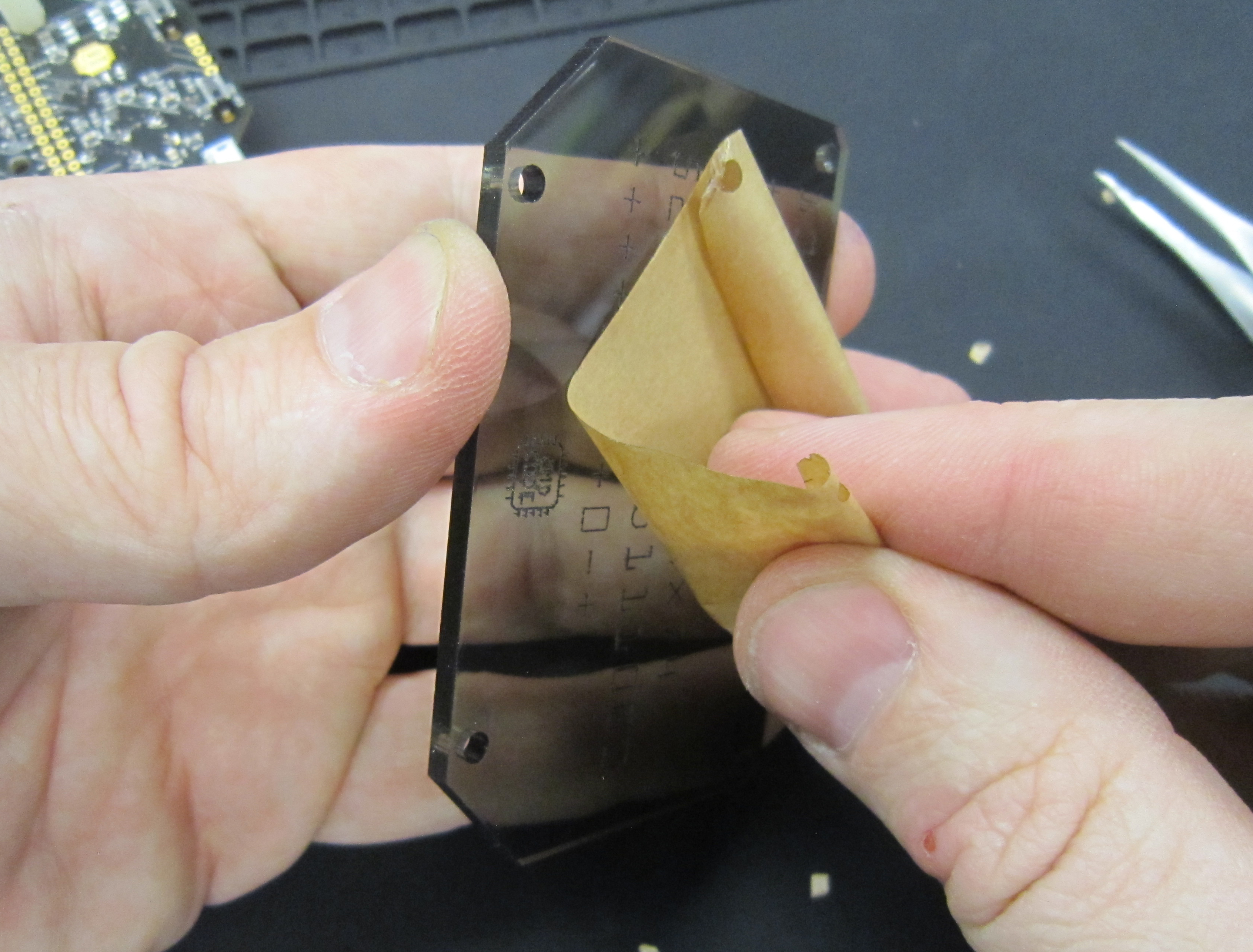
Remove the paper backing on both sides of the acrylic. If there is any residual adhesive, you can use the backing you pulled off to remove the adhesive.
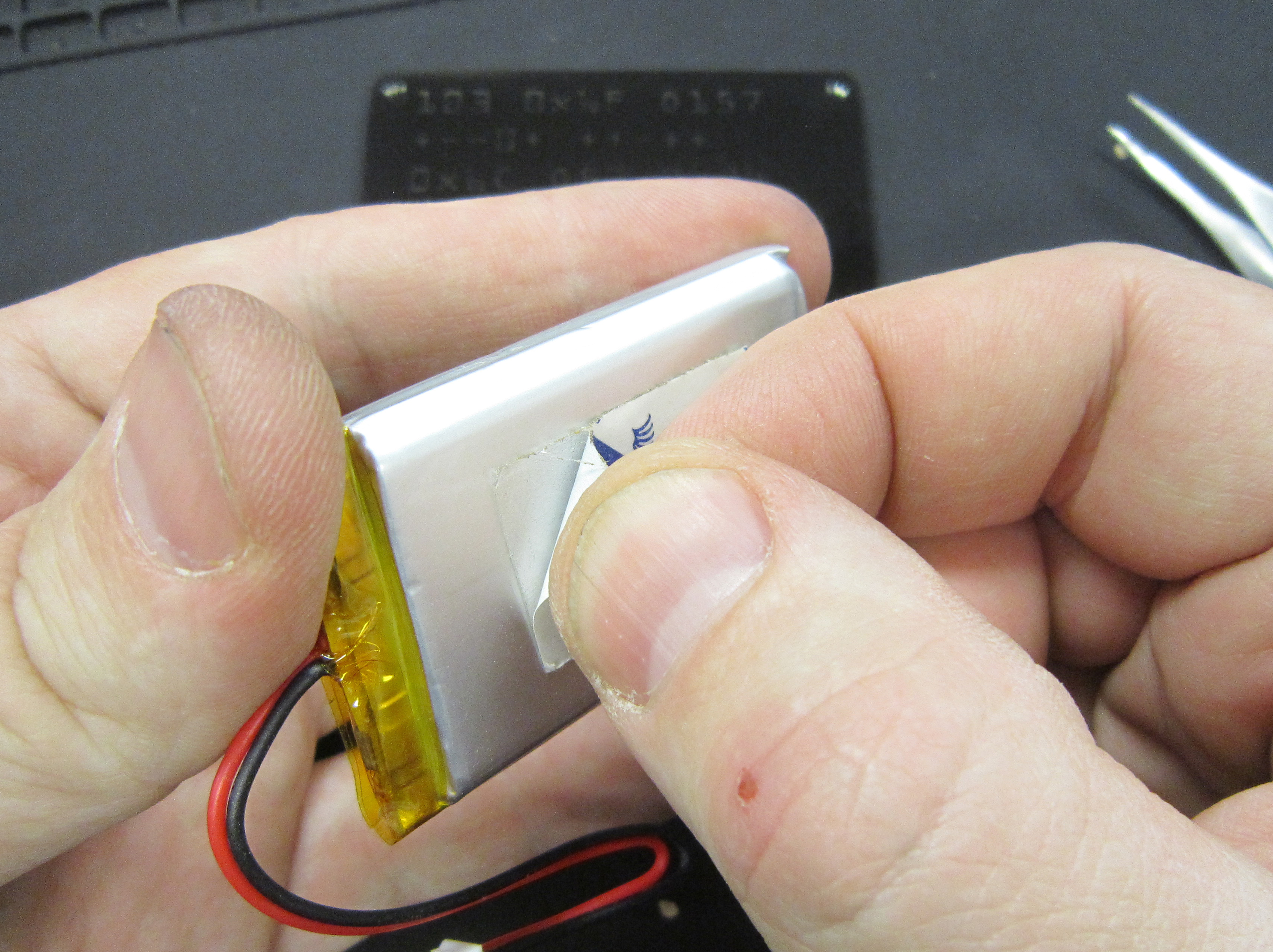
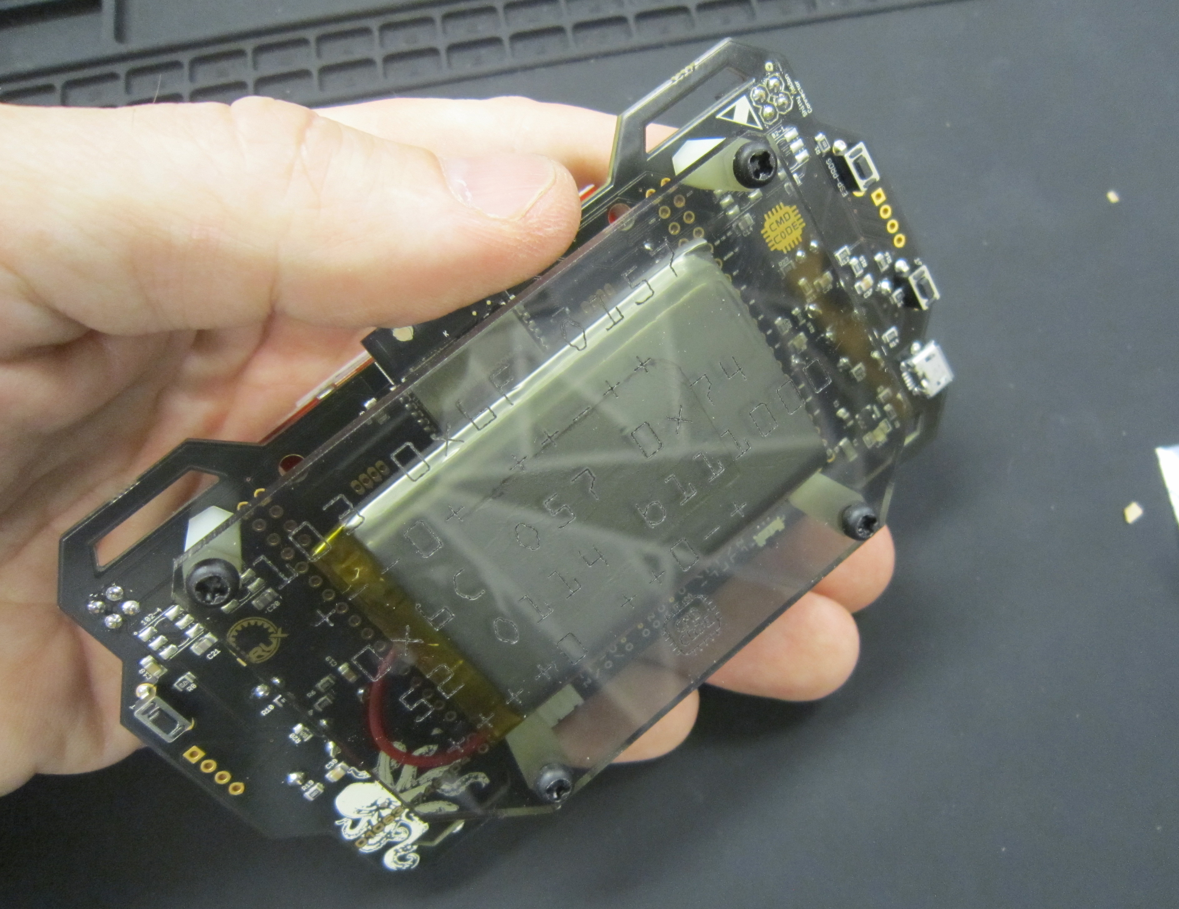
Use a piece of double sided tape and attache the battery to the Acrylic
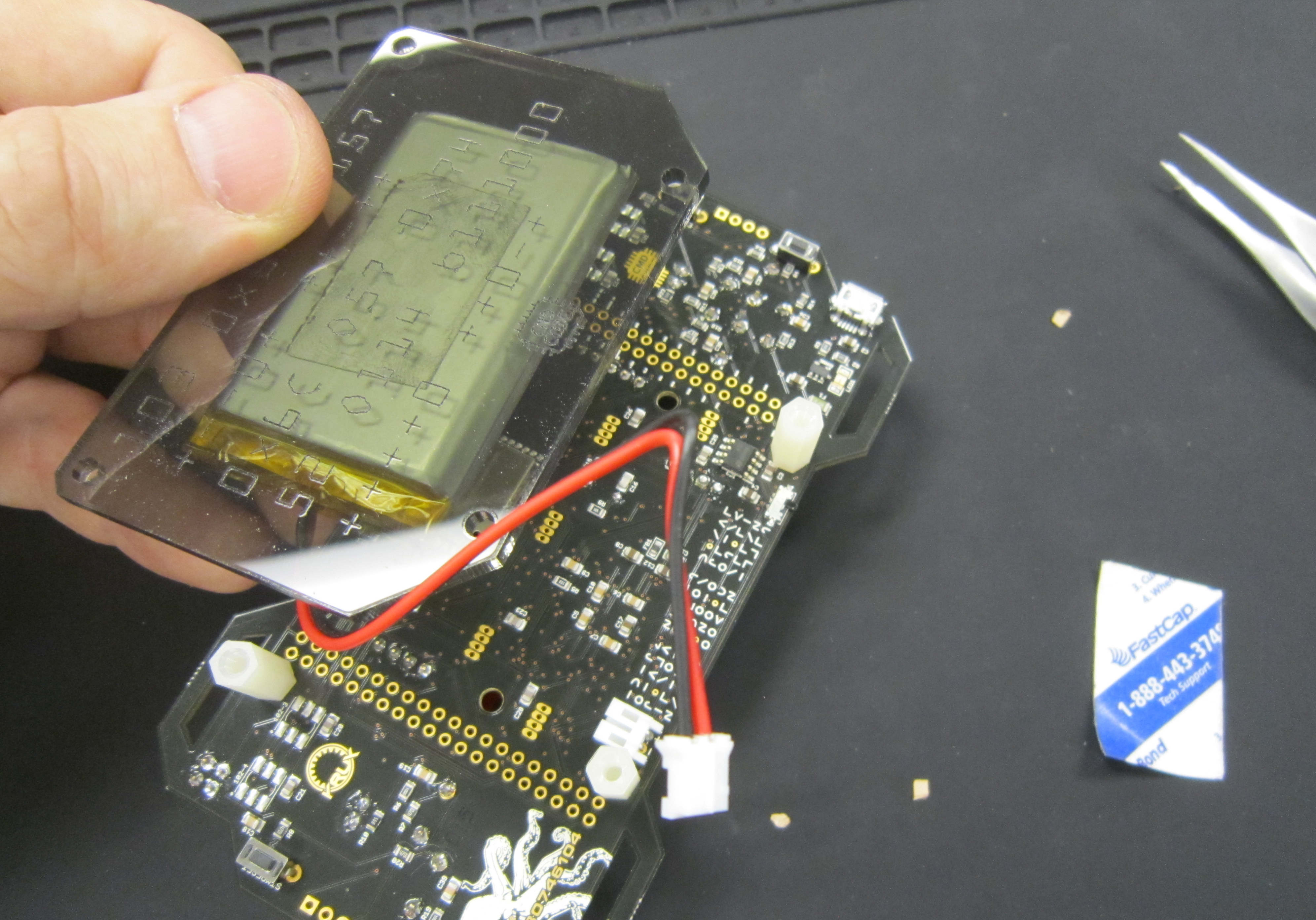
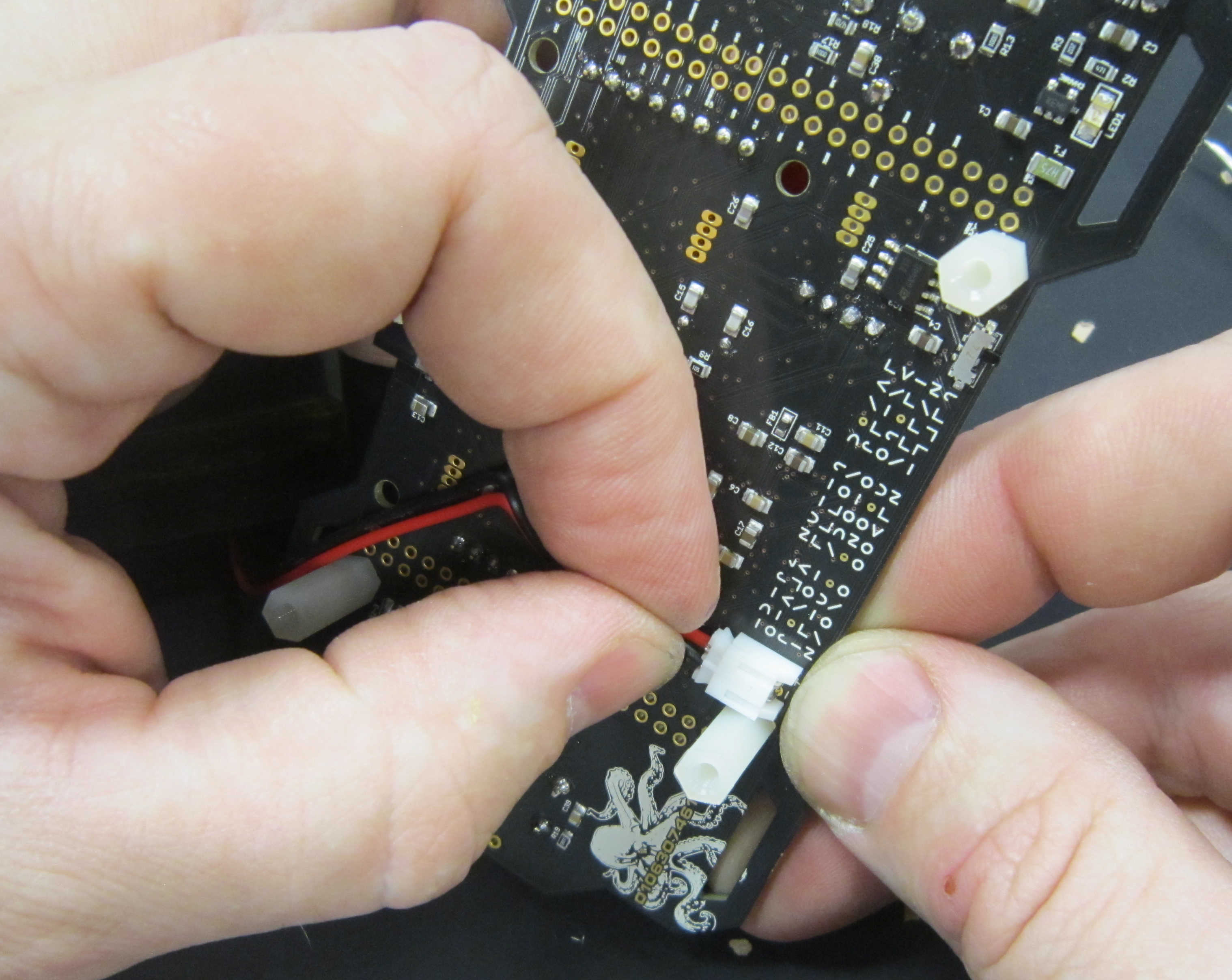
Ensure to turn the badge off before plugging in the battery.
Plug in the Lipo battery.
Attache the acrylic plate to the stand offs.
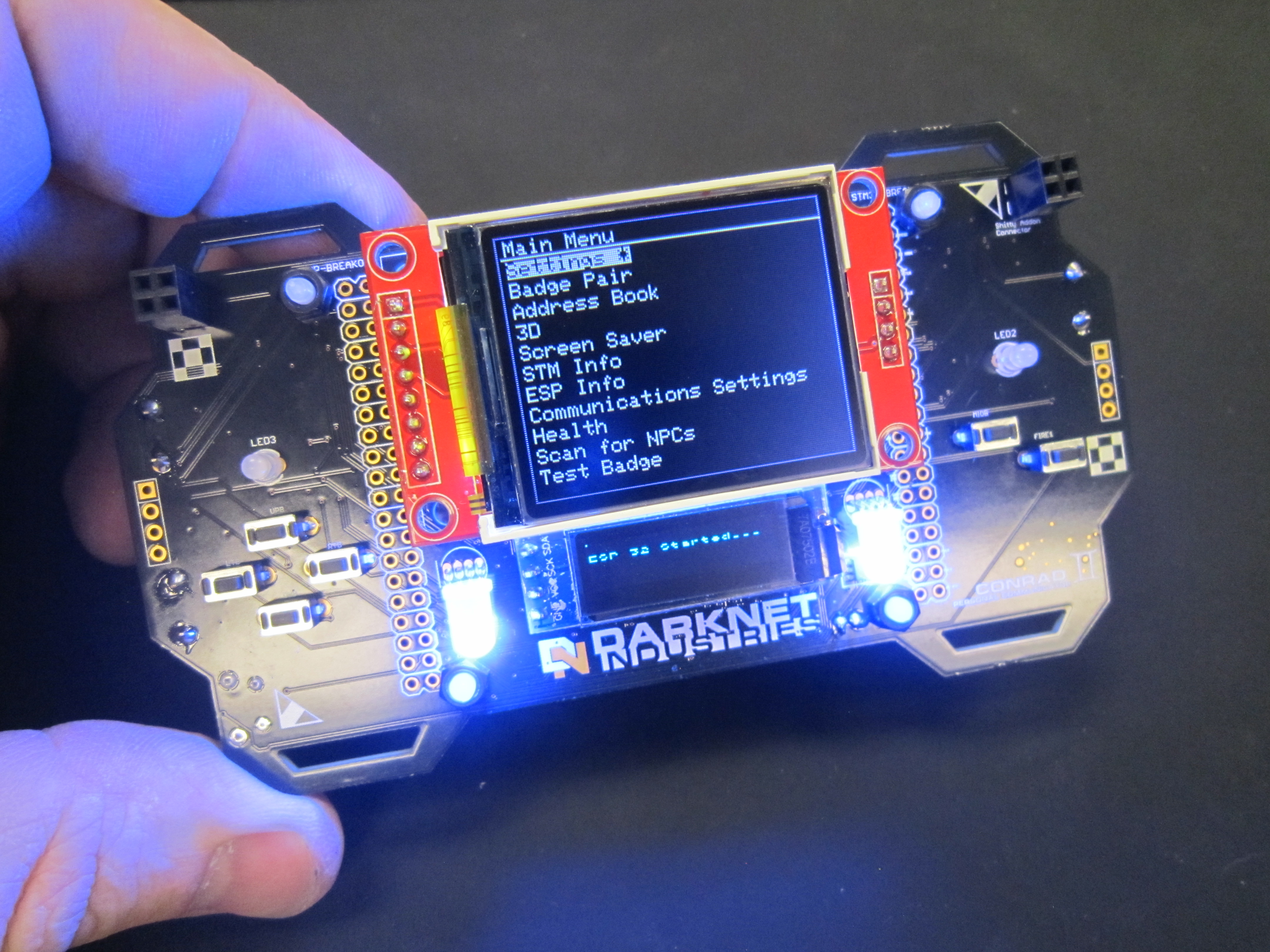
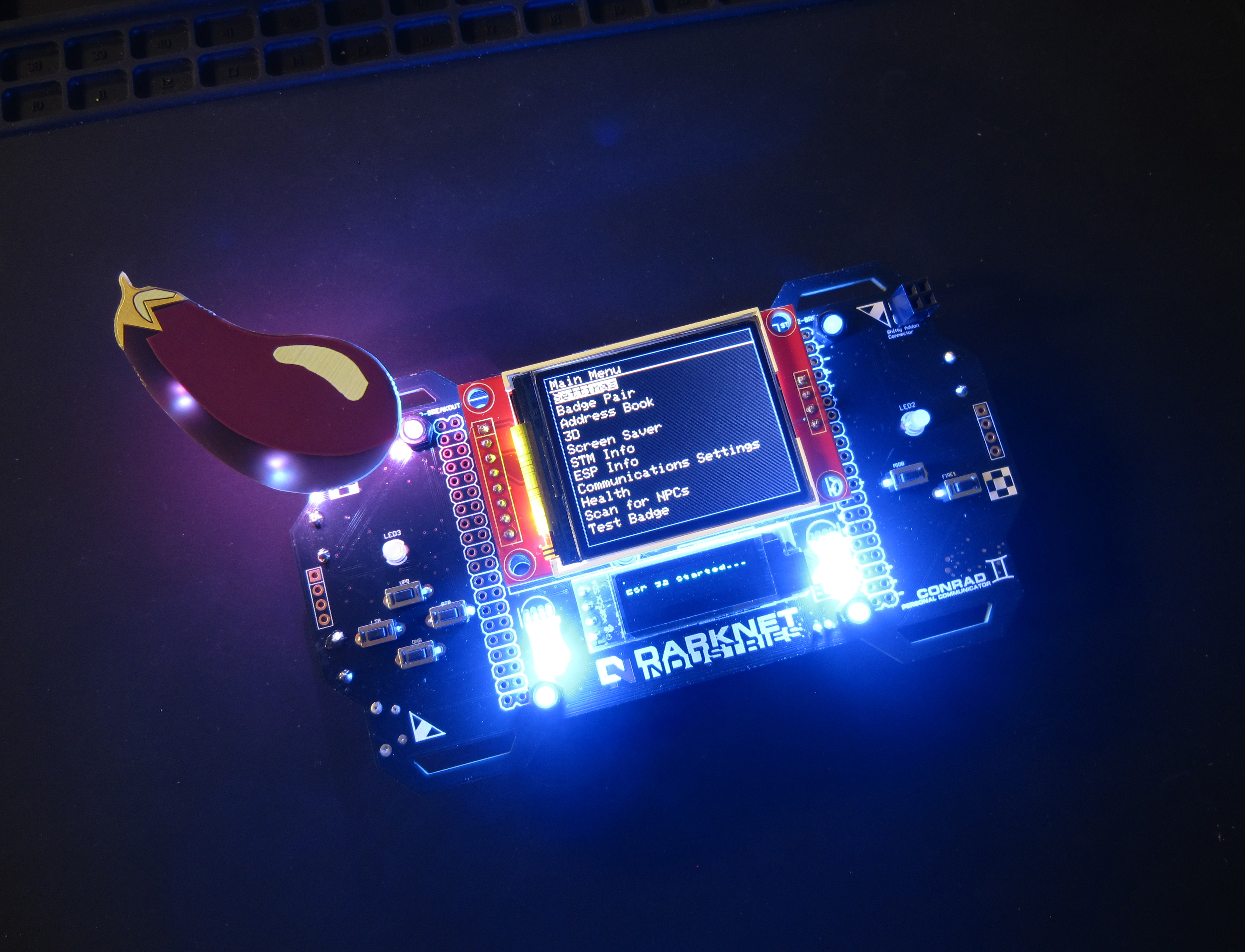
Finally Turn on the badge.
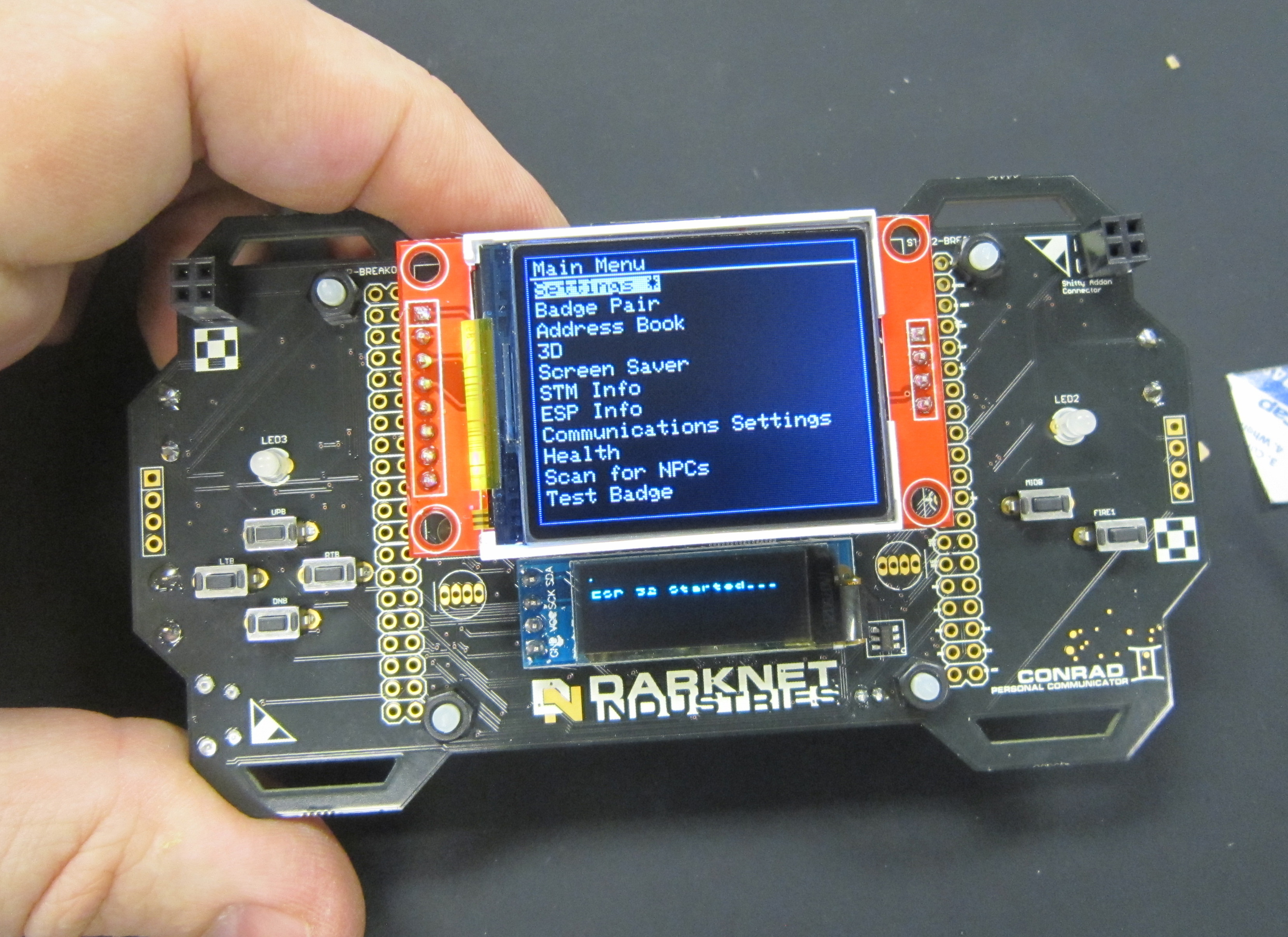
There are several challenges associated with the badge for this year's Darknet contest. Find other players who have badges. Solve the badges silk screen and acrylic puzzles.
![]()
![]()
As stated, this year's badge is a dev kit. So if you either purchased or have an ST-Link programmer for the STM32 and USB to TTL for the ESP 32, you can program the badge to do more cool stuff. This will walk you through soldering the programmable APA-106 LEDs.
Start by removing the acrylic backing, and unplug the lipo battery
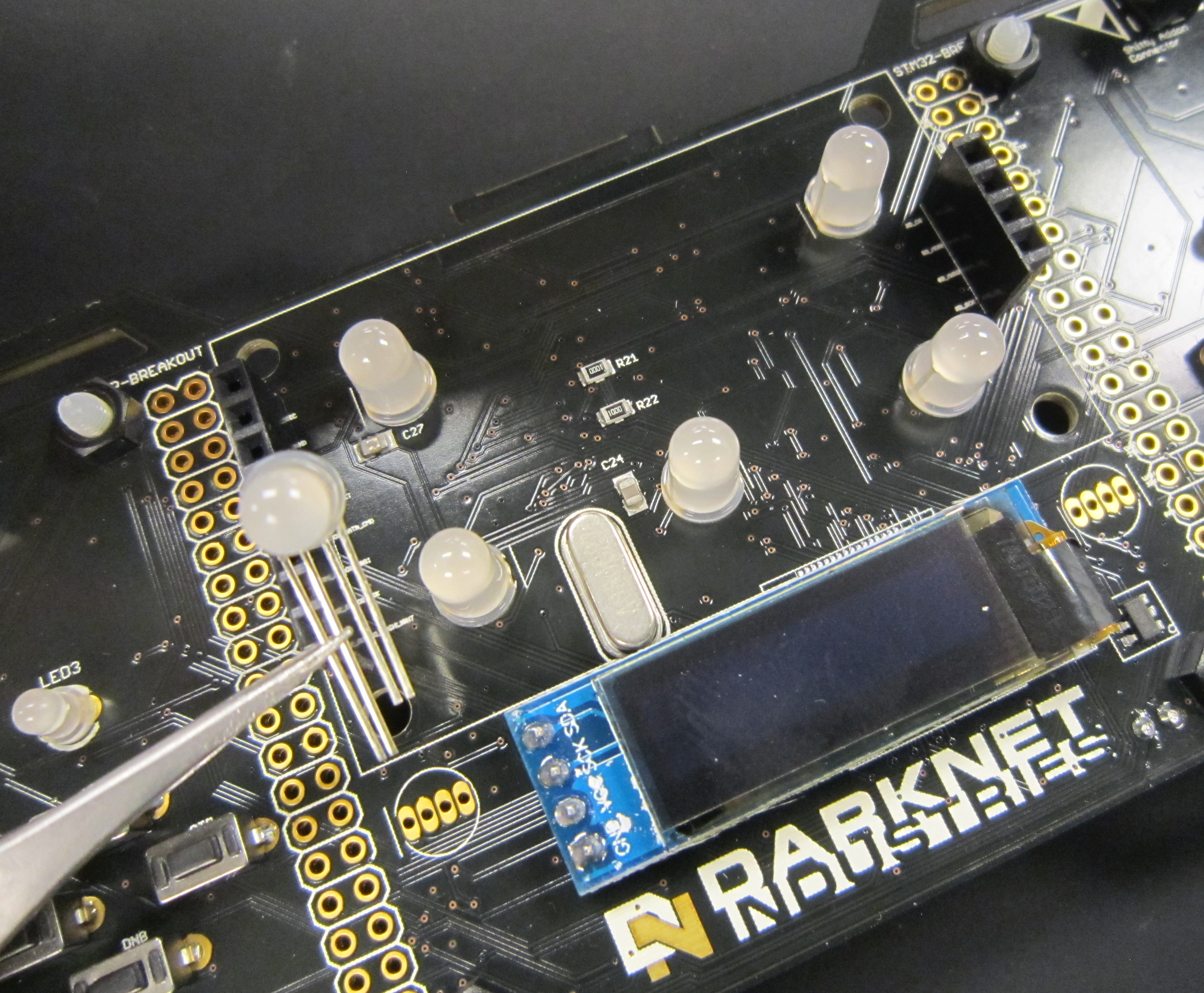
Now we can solder in the LEDs. They are polarized, where the long LEDs correspond to the line on the silk screen.
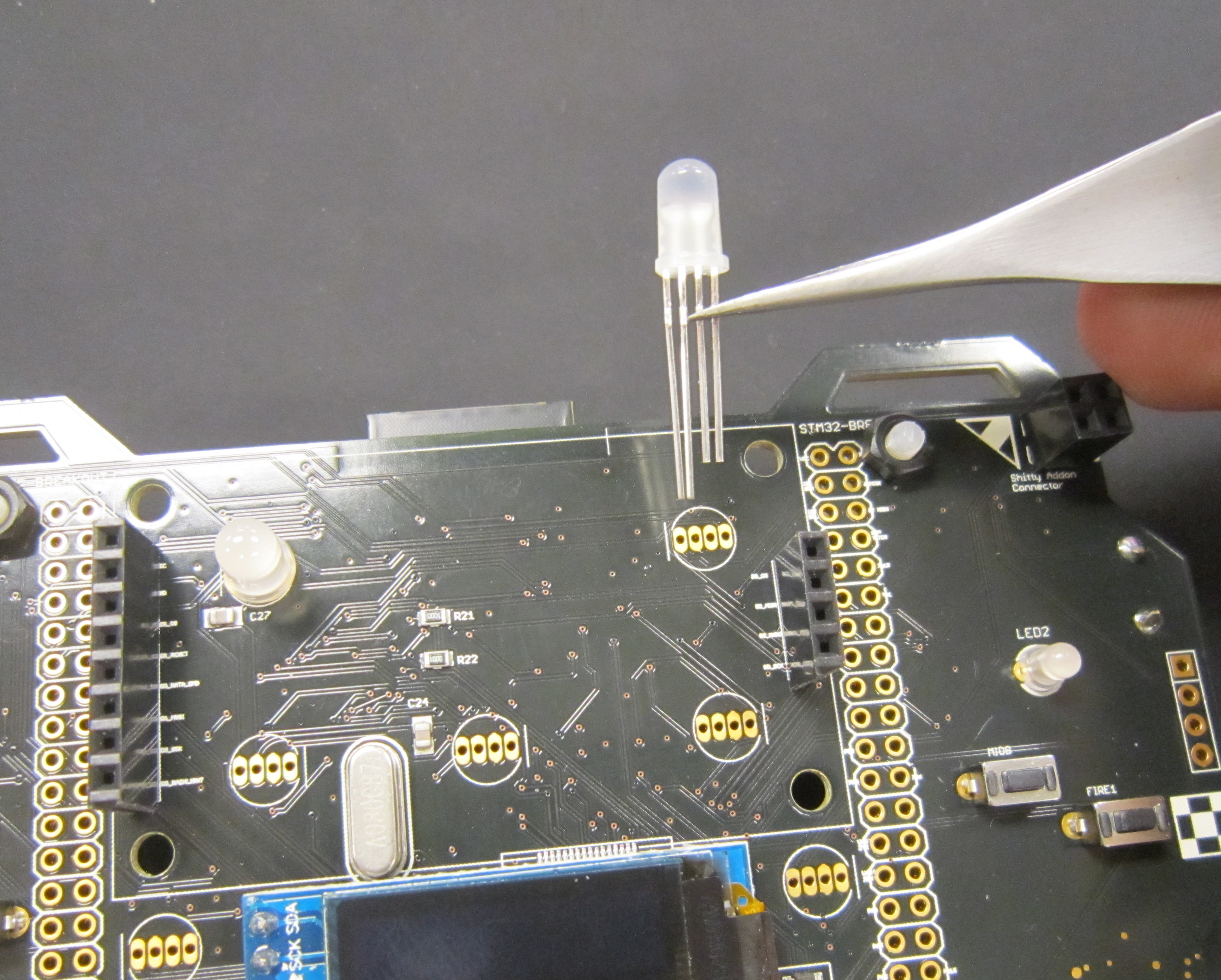
Now we can solder in the LEDs. They are polarized, where the long LEDs correspond to the line on the silk screen.
Solder one pin and check that the LEDs are flush.
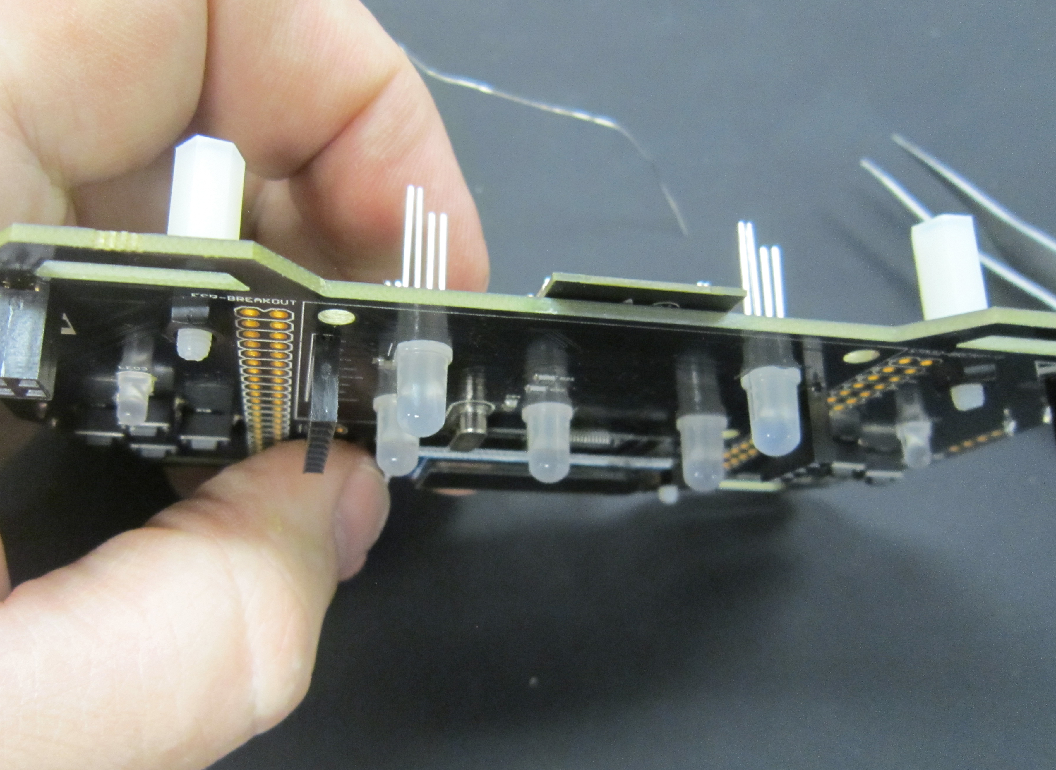
Alternatively you can opt to mount some LEDs at a right angle. For example, the LEDs next to the OLED display would be very bright if looking directly into them, so I opted to mount these at a right angle.
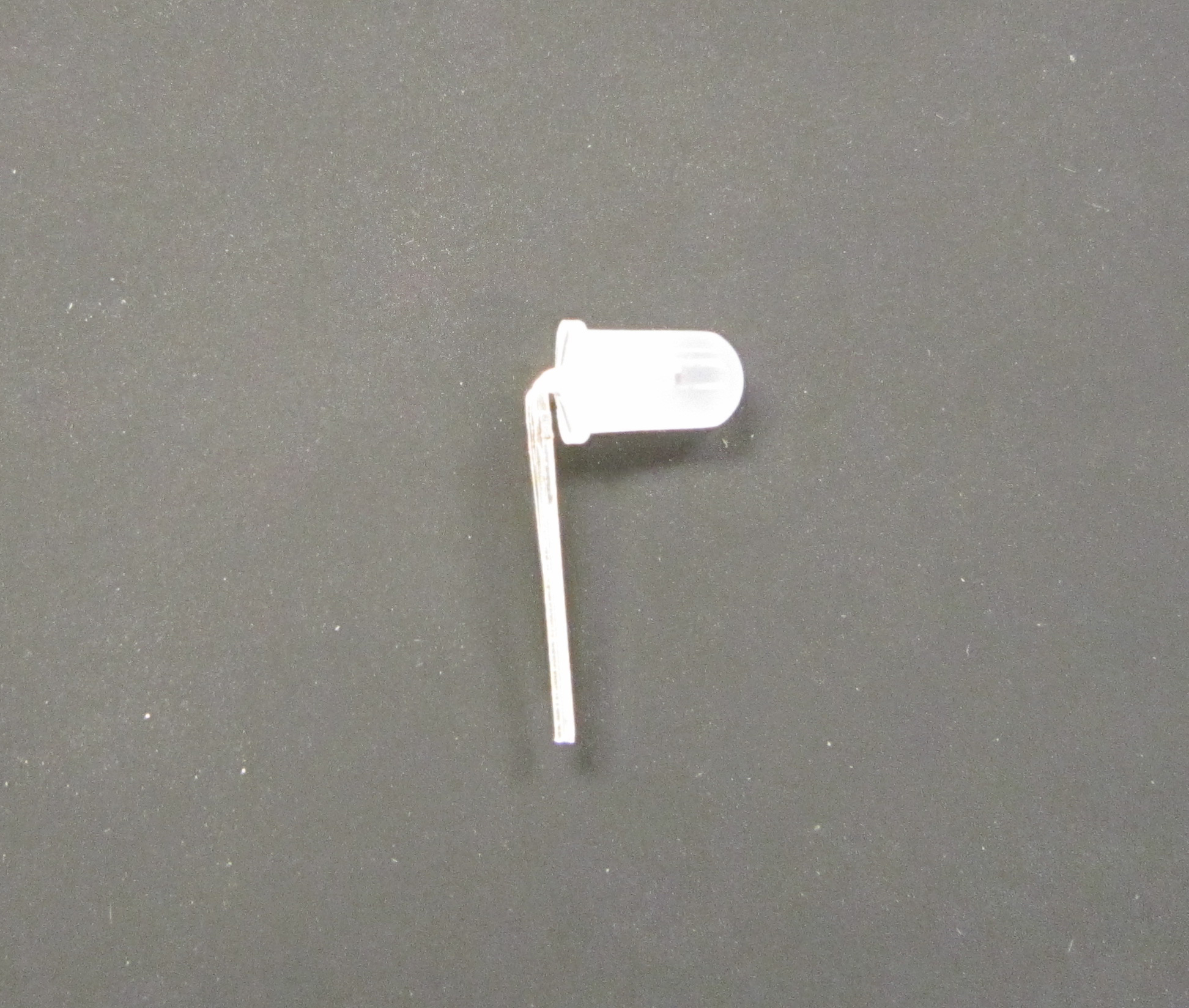
Pay special attention to the LED orientation before bending the LEDs.
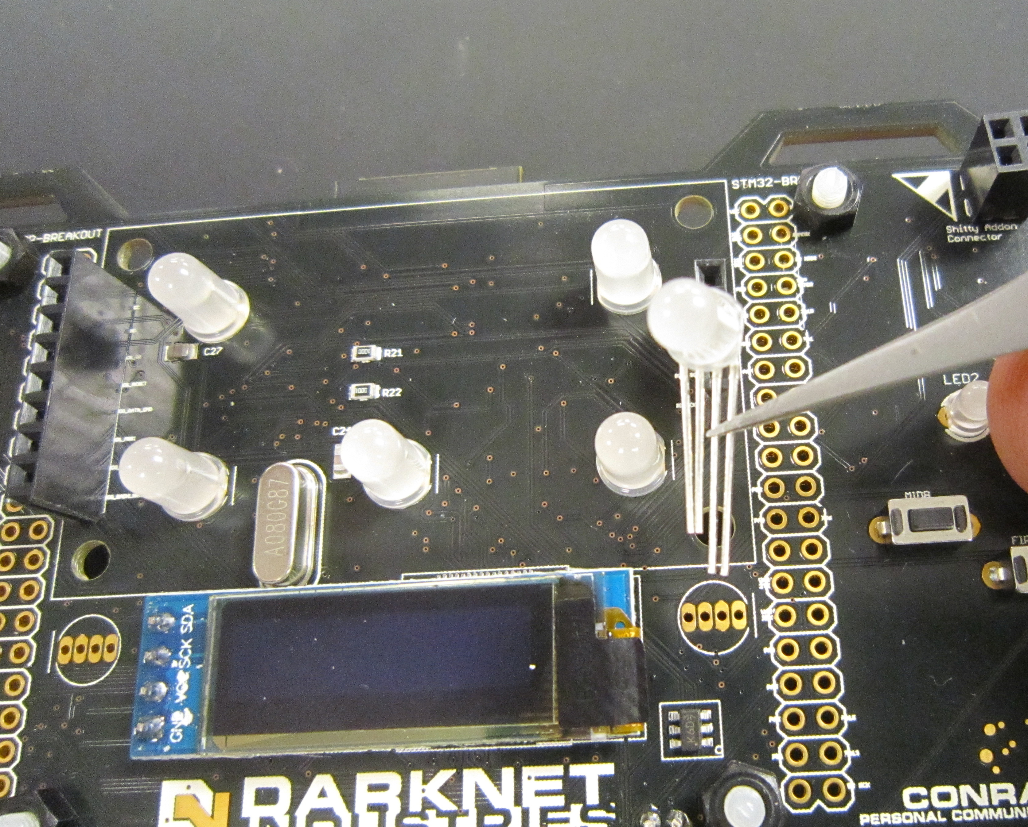
Solder the remaining LEDs in place.
Reassemble your badge and power on.
As the badges come, there is no code in place to control the APA-106 LEDs. If blue is your favorite color, your task is complete, enjoy your awesome badge.
Otherwise take a crack at controlling the the APA-106 LEDs, or if you added them the APA-102 SMD LEDs on the back.
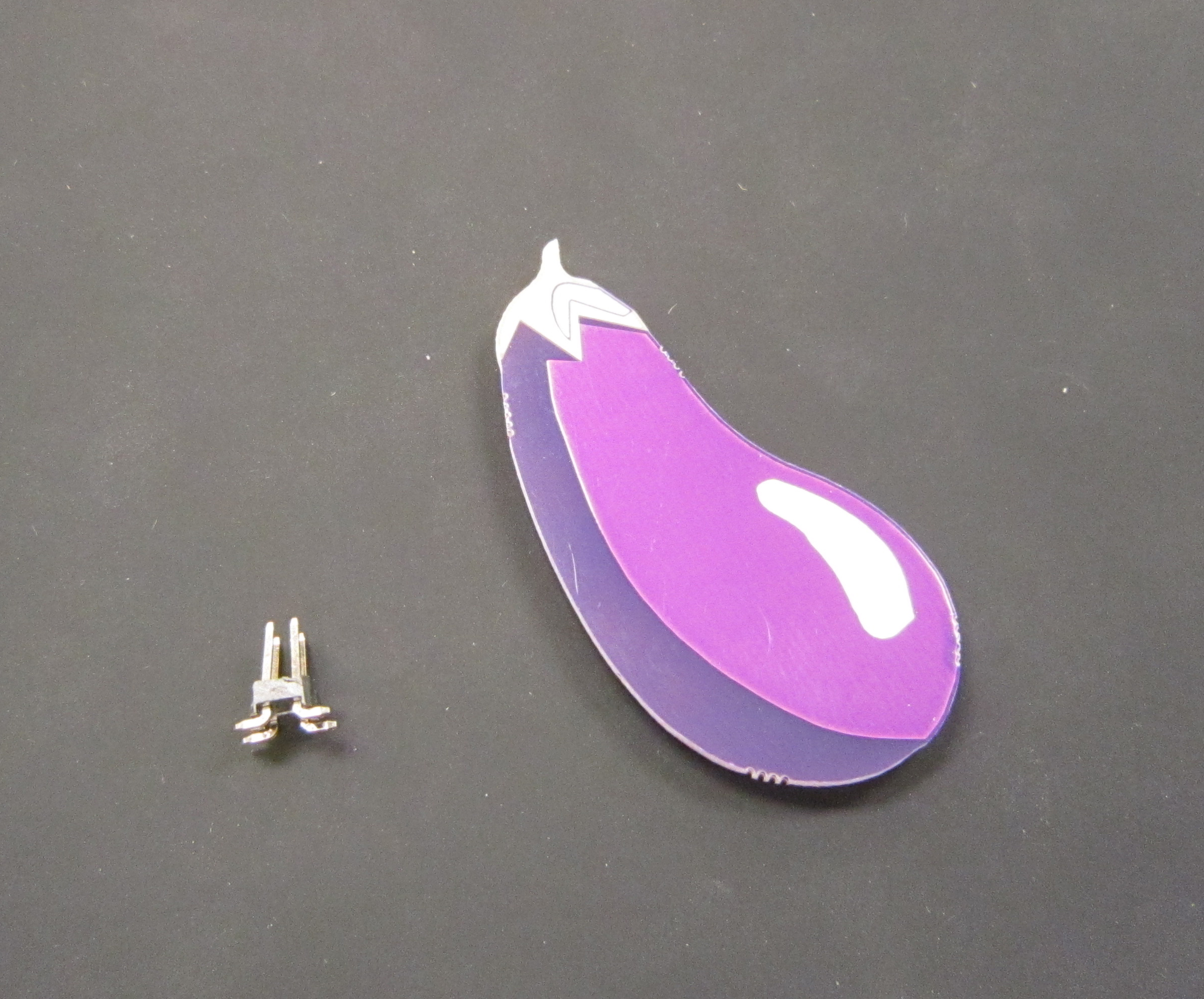
This year, since I (Krux) was not doing the badge hardware, only the badge artwork, I had some time on my hands. And because making Shitty Add-ons are all the rage with the kids these days, decided that making a Darknet appropriate, Eggplant Emoji Shitty Add-on.
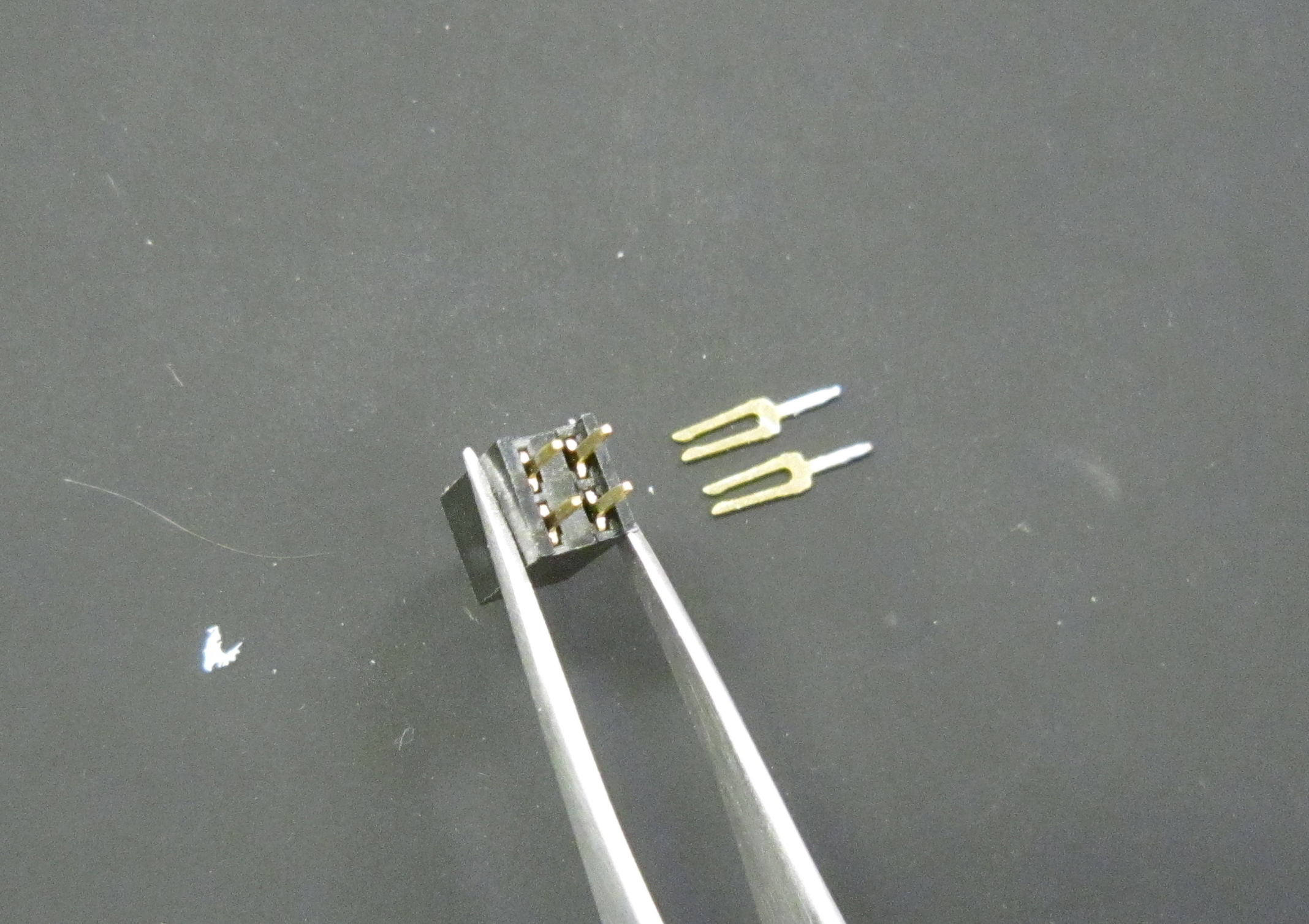
In your Eggplant kit, is the badge itself, driven by an Atmel ATTiny85, and the surface mount four pin header.
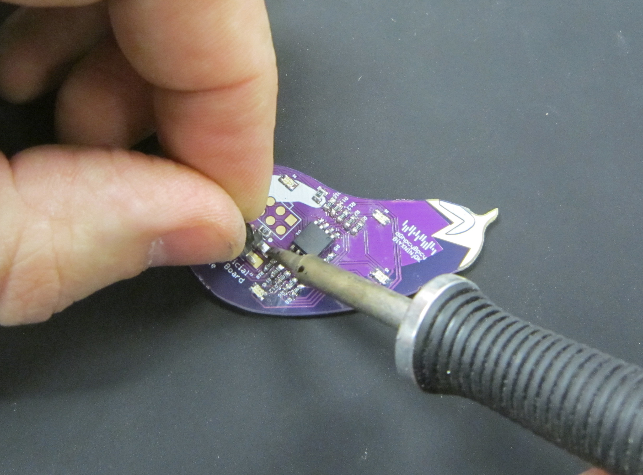
Tin one of the pads for the four pin header.
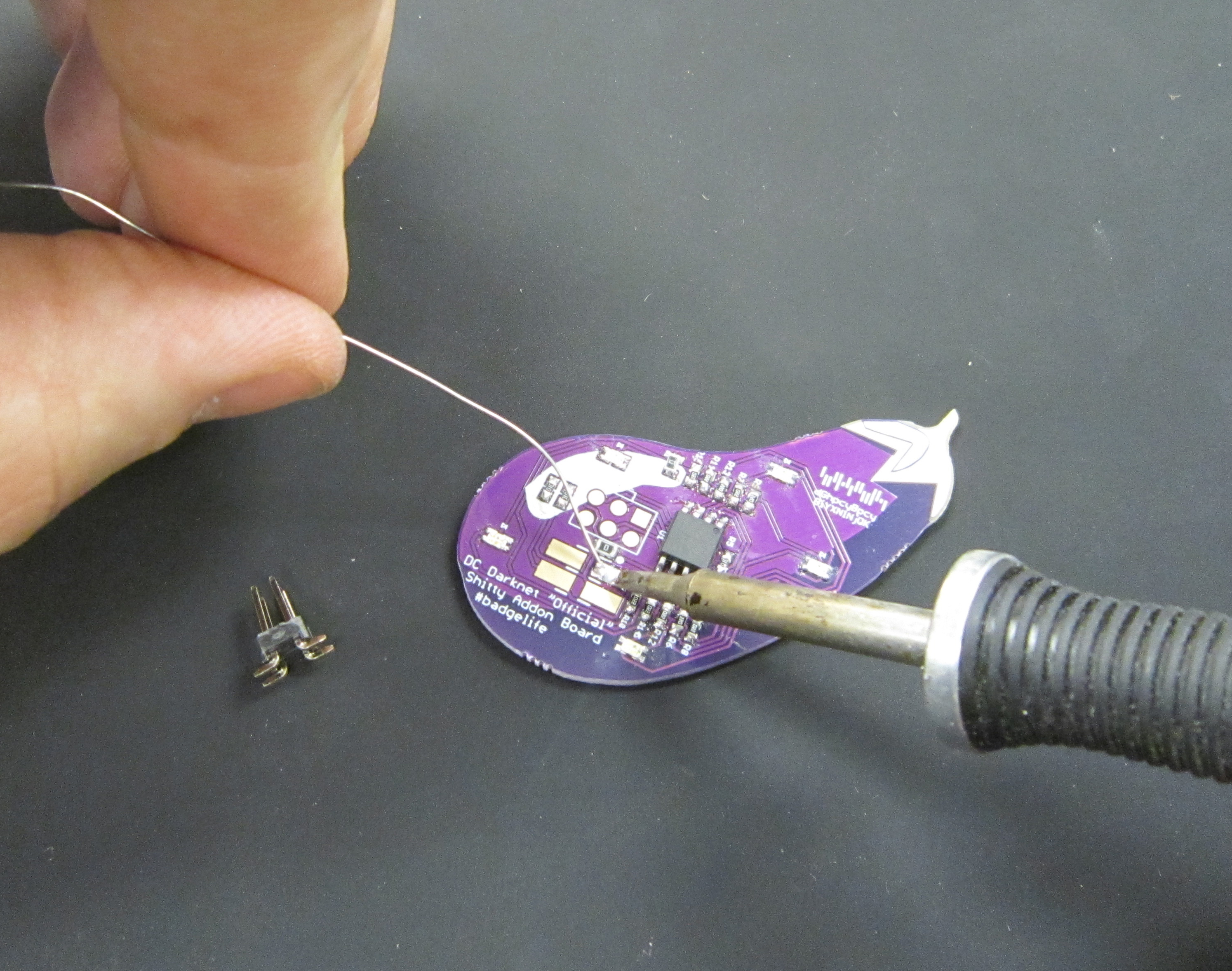
Using the soldering iron to keep the solder molten, move in the four pin header. Unlike what I am doing here, tweezers are a good idea. Otherwise avoid touching the pin that is going to be quickly heated up, which is the method I opted for.
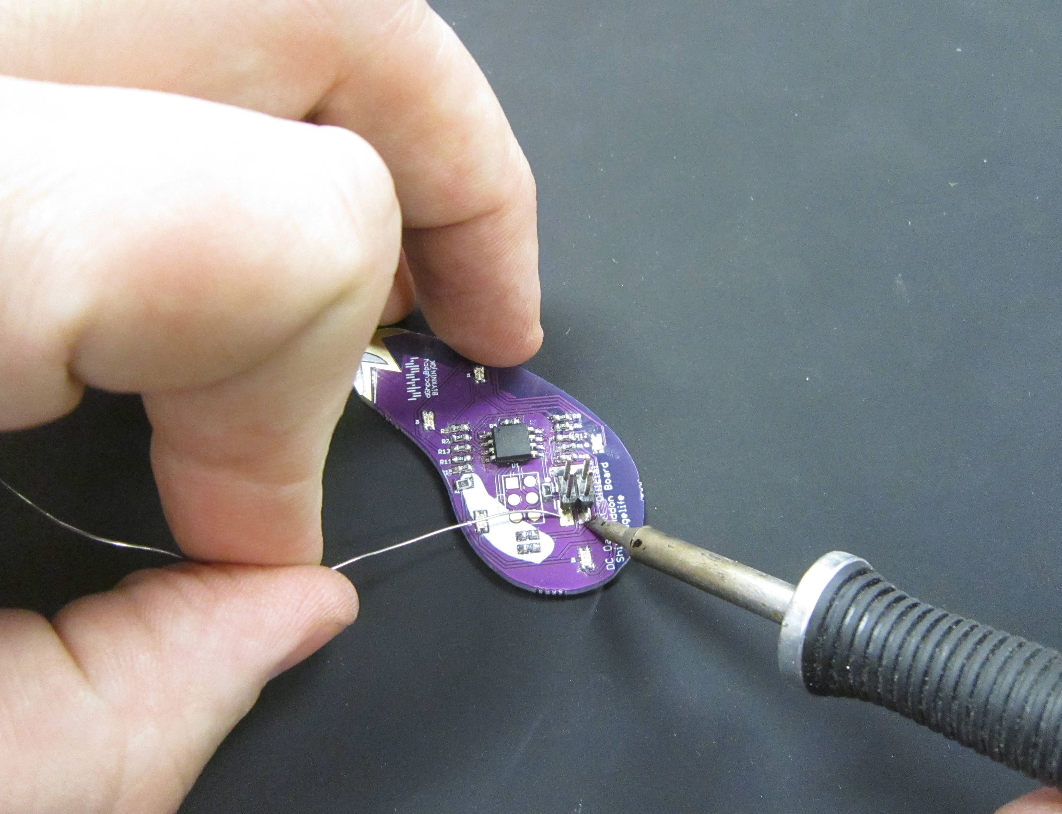
Solder the remaining pins, and retouch the first pin if needed.
Install the Eggplant SAO on the badge's left SAO connector as shown.
Do to a comical miscommunication/and wrong assumptions, when I designed the add-on, The header which I thought was correct, turned out to be the header which Cmdc0de had mirrored. This means that the Eggplant add-on will only really work correctly with the Darknet badge, or another badge that has the pins mirrored. There are a number of SAO adapter plates that are available around DEF CON which could also help you.
Fun for Darknet players, the Eggplant add-on participates in this year's virus game. Name your add-on, and have fun "getting to know" other players.
![]()