These are the assembly instructions for the DefCon DarkNet 2017 Badge Kit.
This badge not only is an excellent opportunity to learn how to solder, if you do not know already, it is also a tool that is used to communicate with other agents participating in the DefCon DarkNet contest. It can be used to pair with other agent's badges, as well as is instrumental in several of the challenges you will encounter when playing with the DarkNet.
Your badge is not programmed with the current firmware. For important Darknet Quest lines, you will need to update your badge with the latest firmware. While at DEF CON come by the Darknet table in the contest area to get your badge updated.
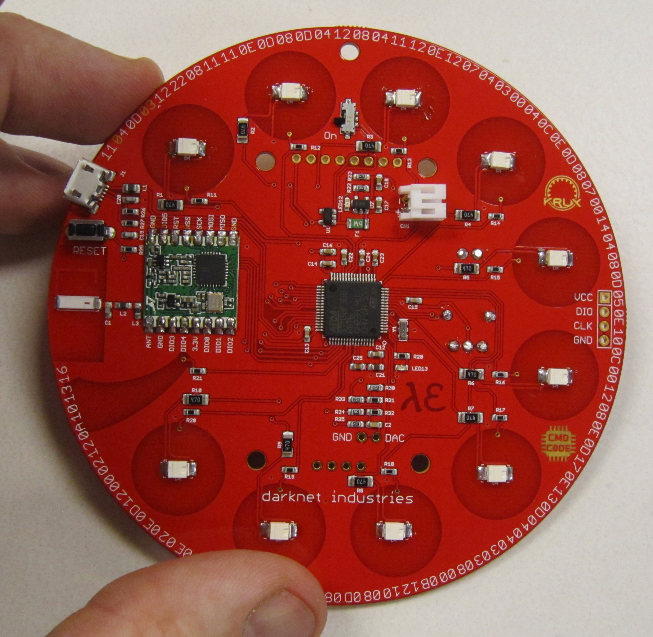
This badge was designed to be easy to solder, as well as hackable. It is based on the ARM Cortex-M4 STM32F302 microcontroller, and can programmed using a ST-Link V2 programmer.
The badge hardware was developed by Krux, and the badge firmware was developed by Cmdc0de.
Avoid common mistakes, and read through this guide in it's entirety before beginning. The order of assembly matters for some components in this kit.
You will need the following tools to assemble this kit
- Temperature controlled soldering station
- Fine solder, 0.032" diameter or smaller
- De-soldering pump / de-soldering braid
- Flush cut wire cutters
- Needle nose pliers
- Fine point tweezers
- Safety glasses
- Optional: PCB vice
- Optional: Flux for SMD use
- Optional: Denatured alcohol to clean the board after soldering
When soldering, it is important to always follow safe work habits. Be mindful of yourself and others. The following documents address some of the safety concerns when soldering
- Soldering Safety
- Lead Soldering Safety Guidelines
- Lead-Free_Solder_Fumes_Increase_Need_for_Fume_Extraction
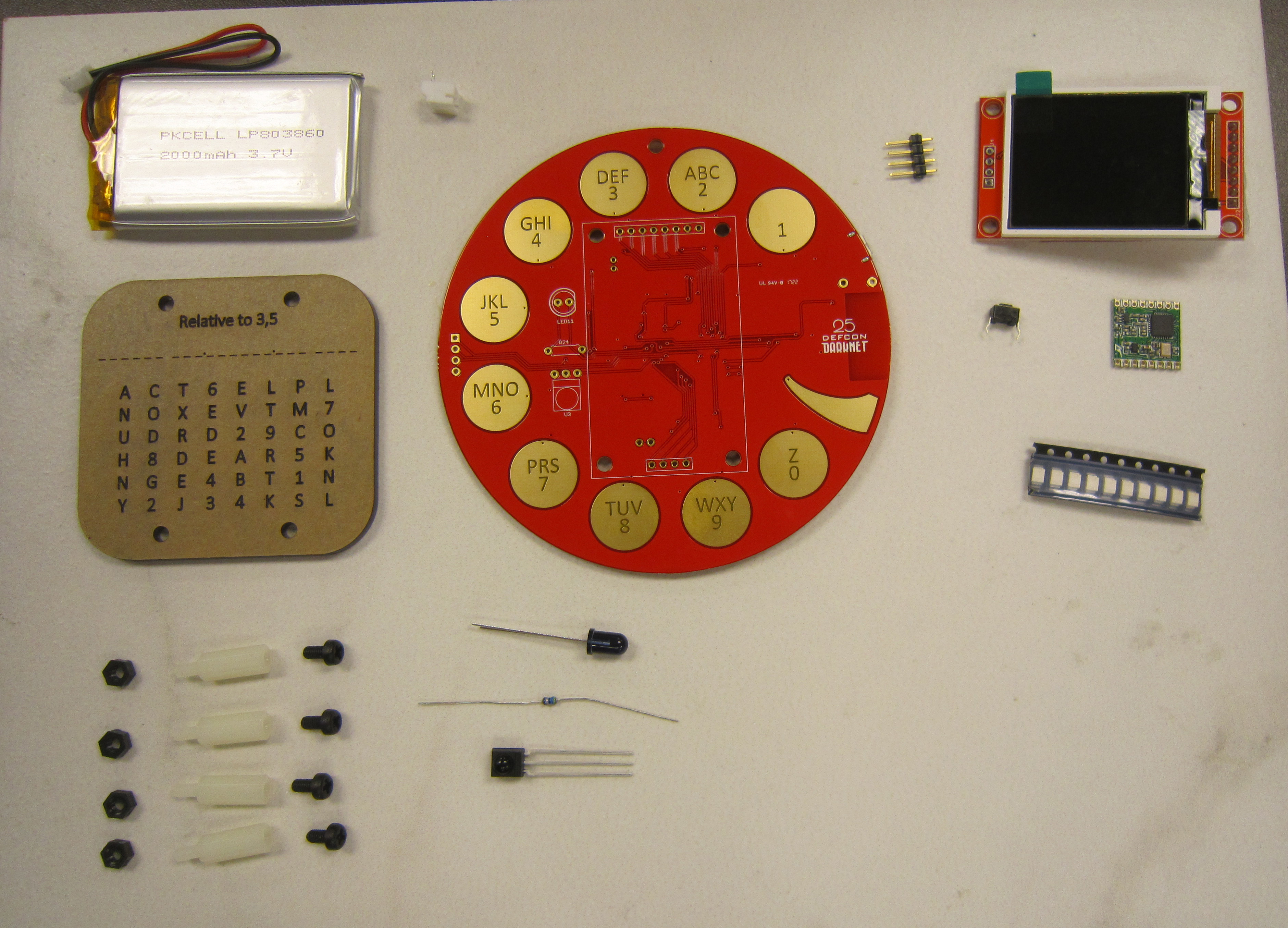
Before you get started, take a moment to ensure that all the components have been included with the kit.
Note: This is also a good time to turn on your soldering iron. For leaded solder, 320 degrees Celsius is a good working temperature.
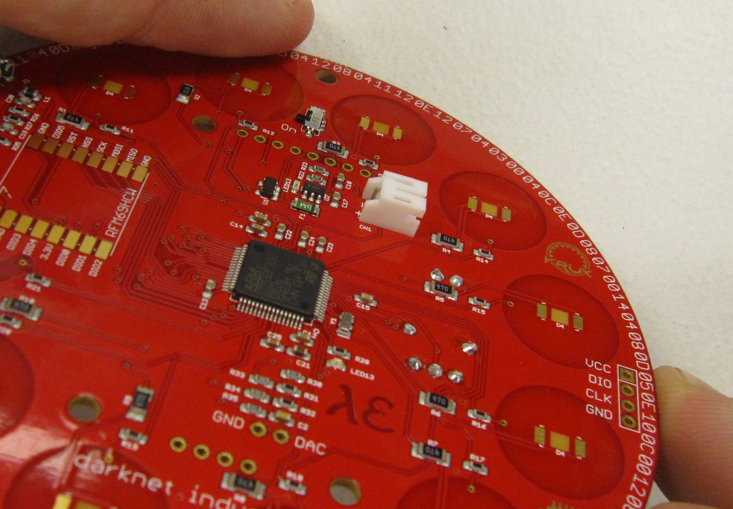
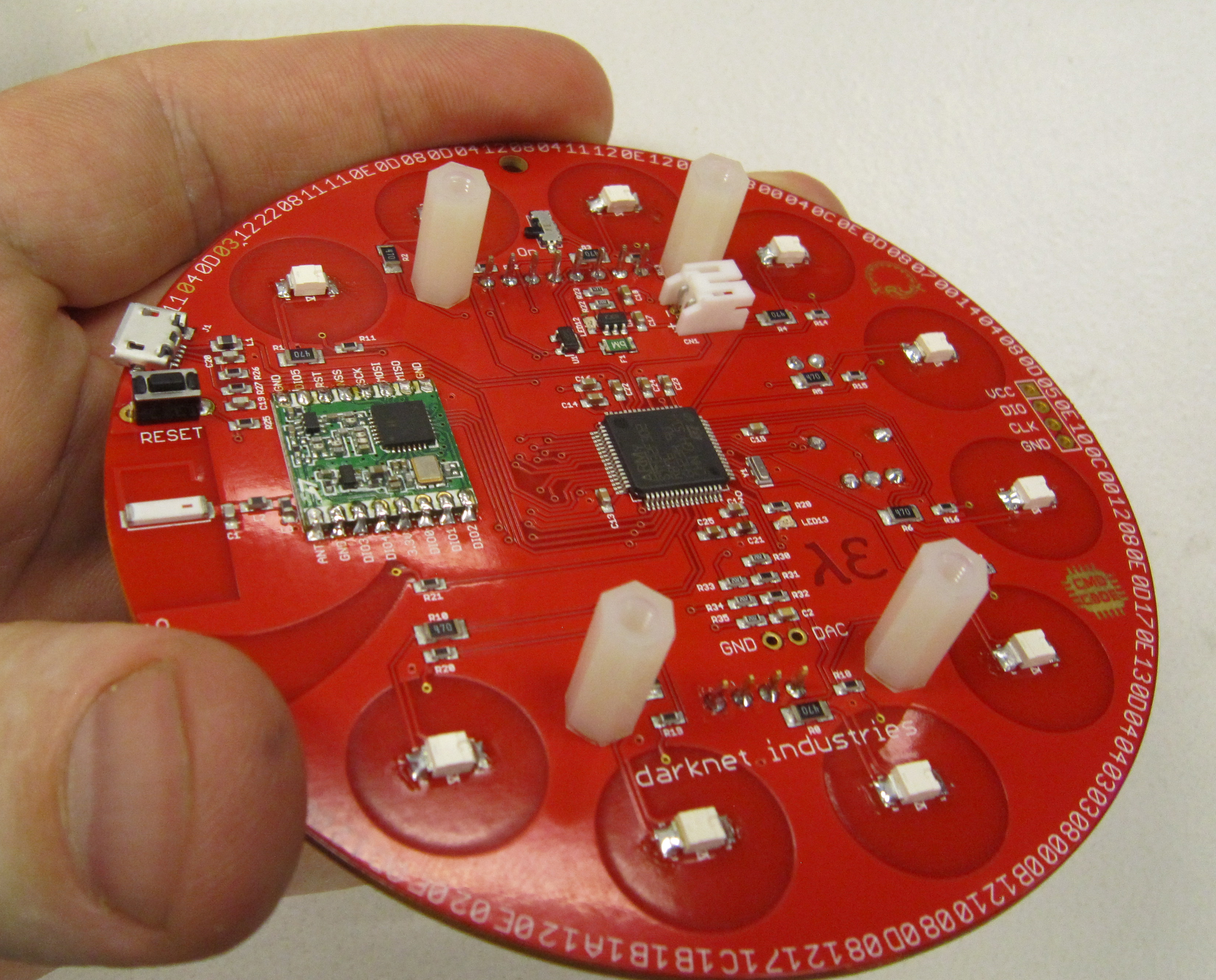
- One darknet rotary circuit board
- One RFM69HCW-915S2 HopeRF radio module
- One color LCD display module
- One four pin male header for LCD display
- One 5mm Vishay IR LED
- One Vishay IR Receiver Module
- One 47 Ohm 1/8W 5% metal film resistors
- One Tactile Switches SPDT
- Ten SMD OSRAM Yellow LEDs
- One Lipo battery
- One JST battery connector
- One acrylic backing (to Velcro battery to)
- Four 3mm nylon nuts
- Four 3mm nylon screws
- Four nylon standoffs
- One DefCon DarkNet Lanyard
Click on any of the images for a high-resolution version.
This kit contains both through hole and surface mount components. Component selection was set so that the surface mount parts should be easy for people to solder while at DEF CON, even by those inexperienced at soldering, using the tools provided in the Hardware Hacking Village.
When soldering PCBs, best practice (though not a hard fast rule) is to solder components from lowest/smallest to tallest/largest. As such surface mount parts usually fall within the lowest/smallest range. This assumes that you are working by resting the board on a flat surface, and so you want to avoid adding parts which cause the board not to sit flat while working on it. With through hole parts, the weight of the board can be used to help keep them in place by using this method. With surface mount parts you want your board to remain as stable as possible while soldering these components.
There are also other tools which can help in soldering, such as PCB vices, which hold the board from the sides. However I would avoid using tools such as inexpensive helping hands with alligator clips, as these do not work well for keeping PCBs stable when soldering. And in instances where you cannot avoid having parts in place which prevent a board from laying flat and stable, you can prop up the board on a surface and let larger components overhang to form a stable working environment.
It is generally easier to solder the surface mount components to the board before the through hole components are added. This lets you work with the board on a steady flat surface. And prevents the board from moving around when you are trying to solder smaller components like the backlight LEDs.
However if you have never soldered before, or even have done some soldering but consider yourself inexperienced, it is easier to learn the methods of soldering by working with through hole components first. Which is how this guide is written.
For an experienced solderer, I would suggest reading through this entire guide before starting, and use which ever order you feel would be best for you.
For the inexperienced solderer, I would suggest reading through this entire guide before starting, and following along as written.
Start by bending the leads as shown, so they may be inserted into PCB.
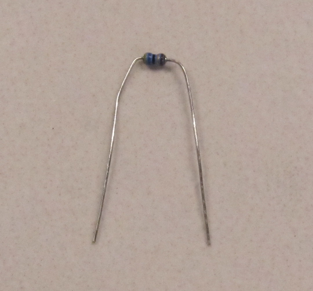
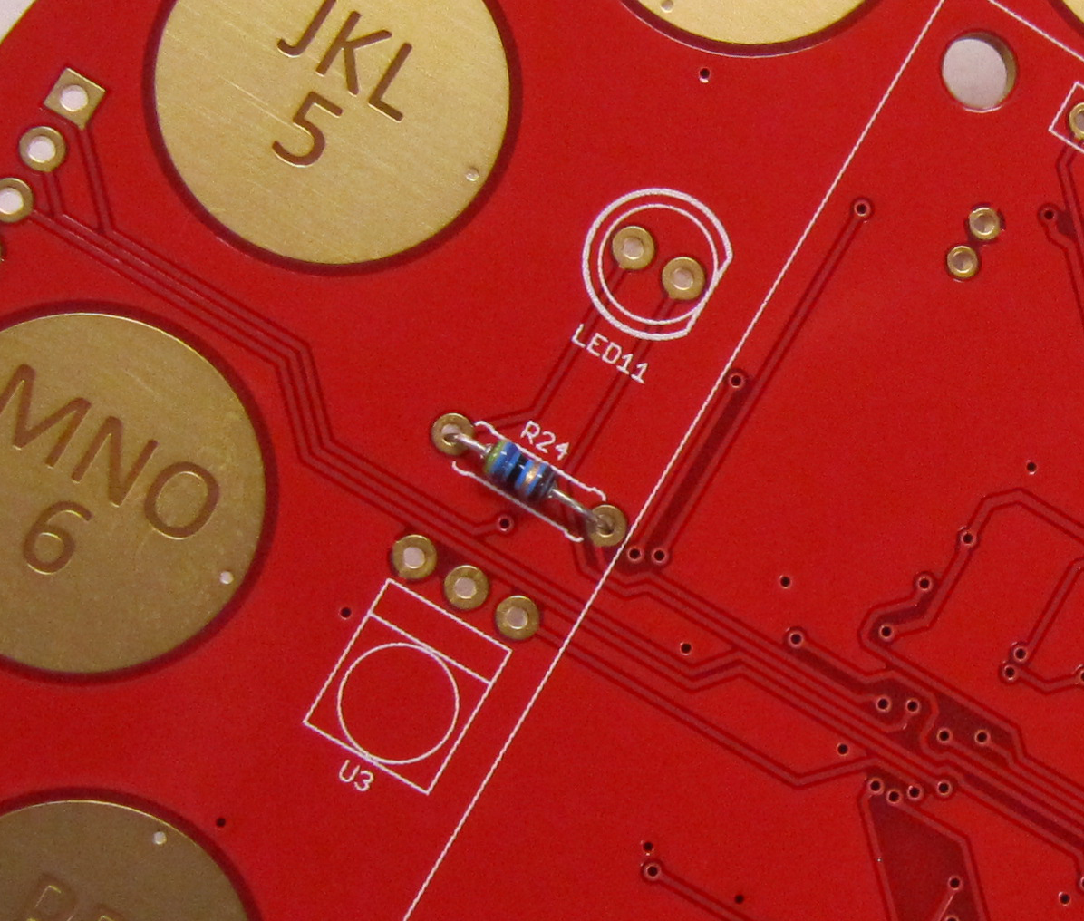
Populate the components, so they are on the top side of the board. Each component is marked with it's part designator. The parts should lay flush with the PCB. Insert the resistor in R24, as shown.
To aid in soldering, and to help keep the components in place, the leads may be splayed at a slight angle to hold the parts in place. Double check that the parts are still flush with the PCB before soldering.
Ensure the tip of your soldering iron is always kept clean. It should be shiny in appearance. Removing the oxidation by wiping the soldering iron on a solder sponge.
When using a chisel tip as show, the flat of the tip can be used. When using a conical tip, use the section of the iron just to the side of the tip. This gives you a larger area of thermal contact and will make soldering easier.
Begin soldering by positioning the tip of the iron so that it makes firm contact with both the solder pad on the PCB and the lead of the component. This ensures that both the pad and the part both get sufficiently hot so that they are able to melt the solder and make a good electrical connection. Feed solder in sparingly on the side opposite the soldering iron. The solder should flow on the solder pad and lead of the component, forming a conical shape.
The following diagram shows more details on soldering DOs and DON'Ts
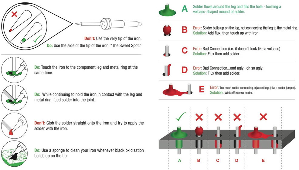
Solder the resistor leads using the method explained above.
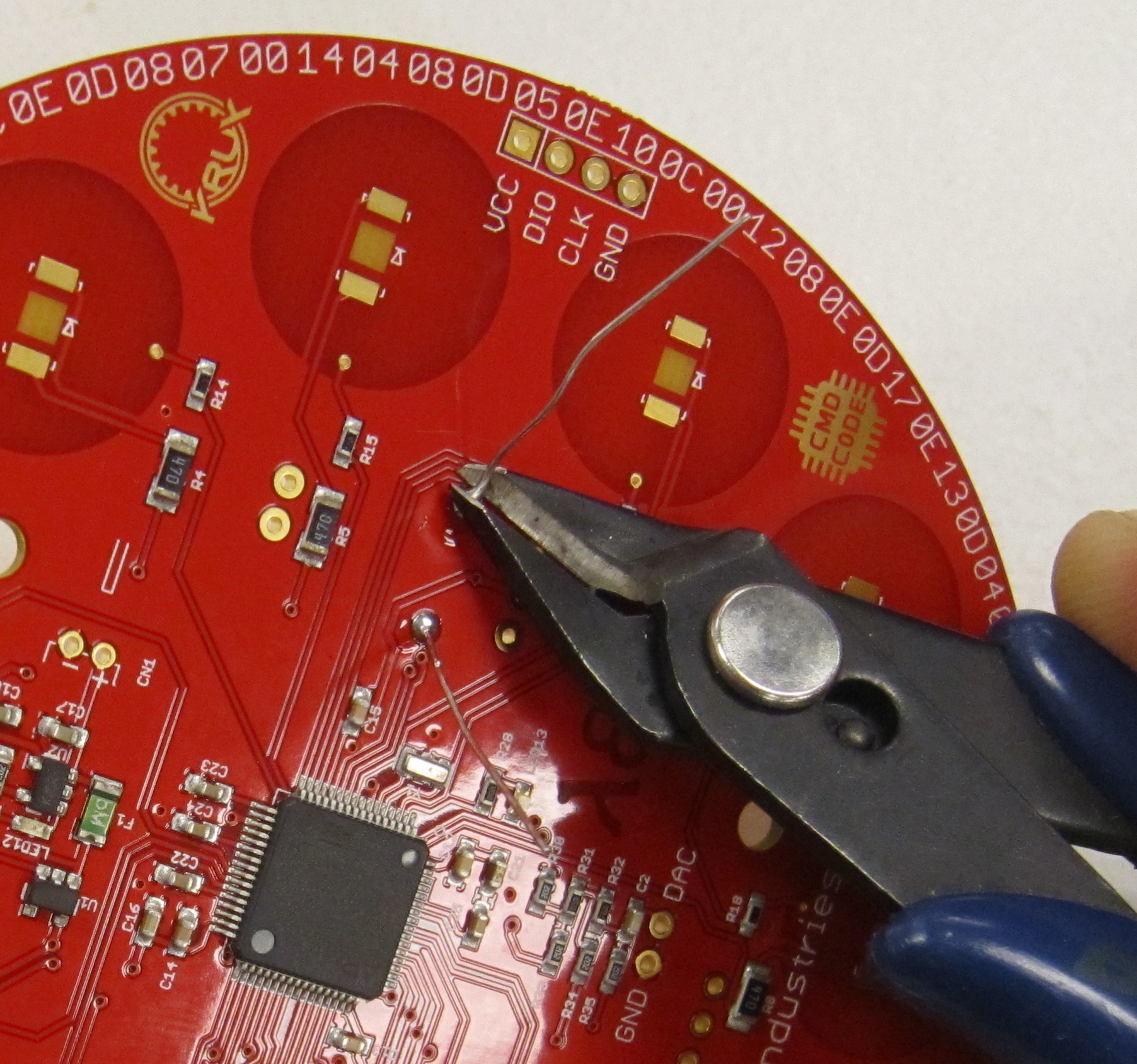
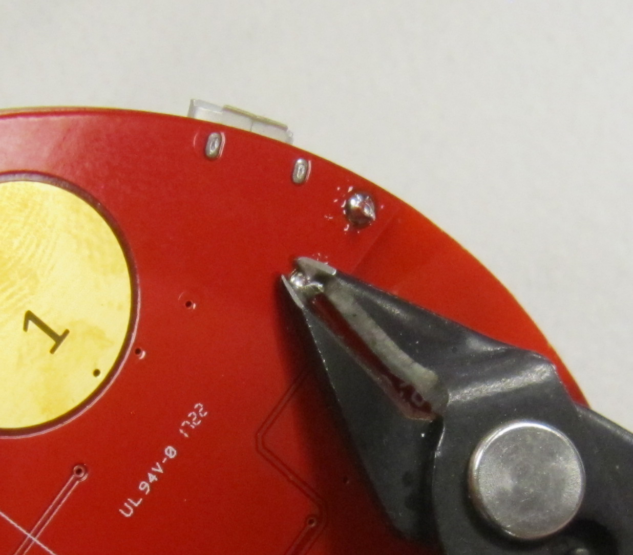
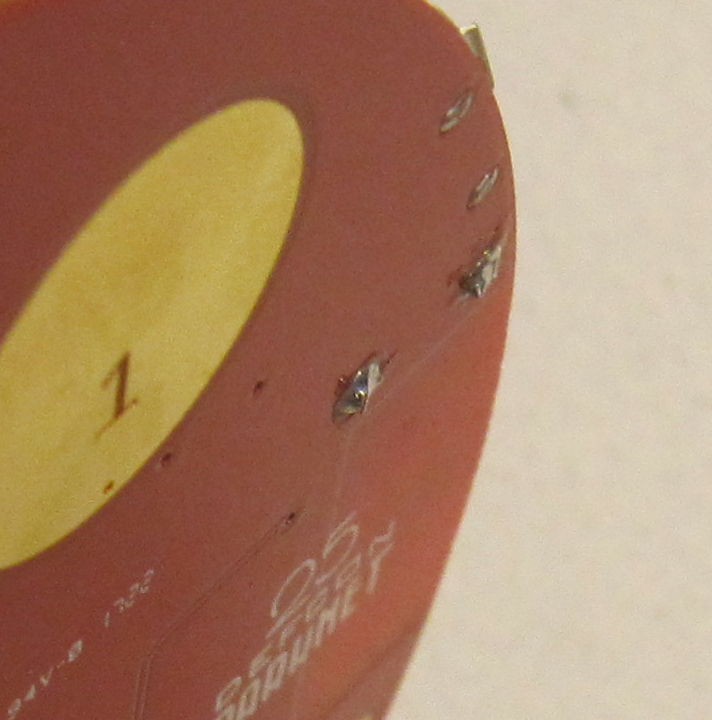
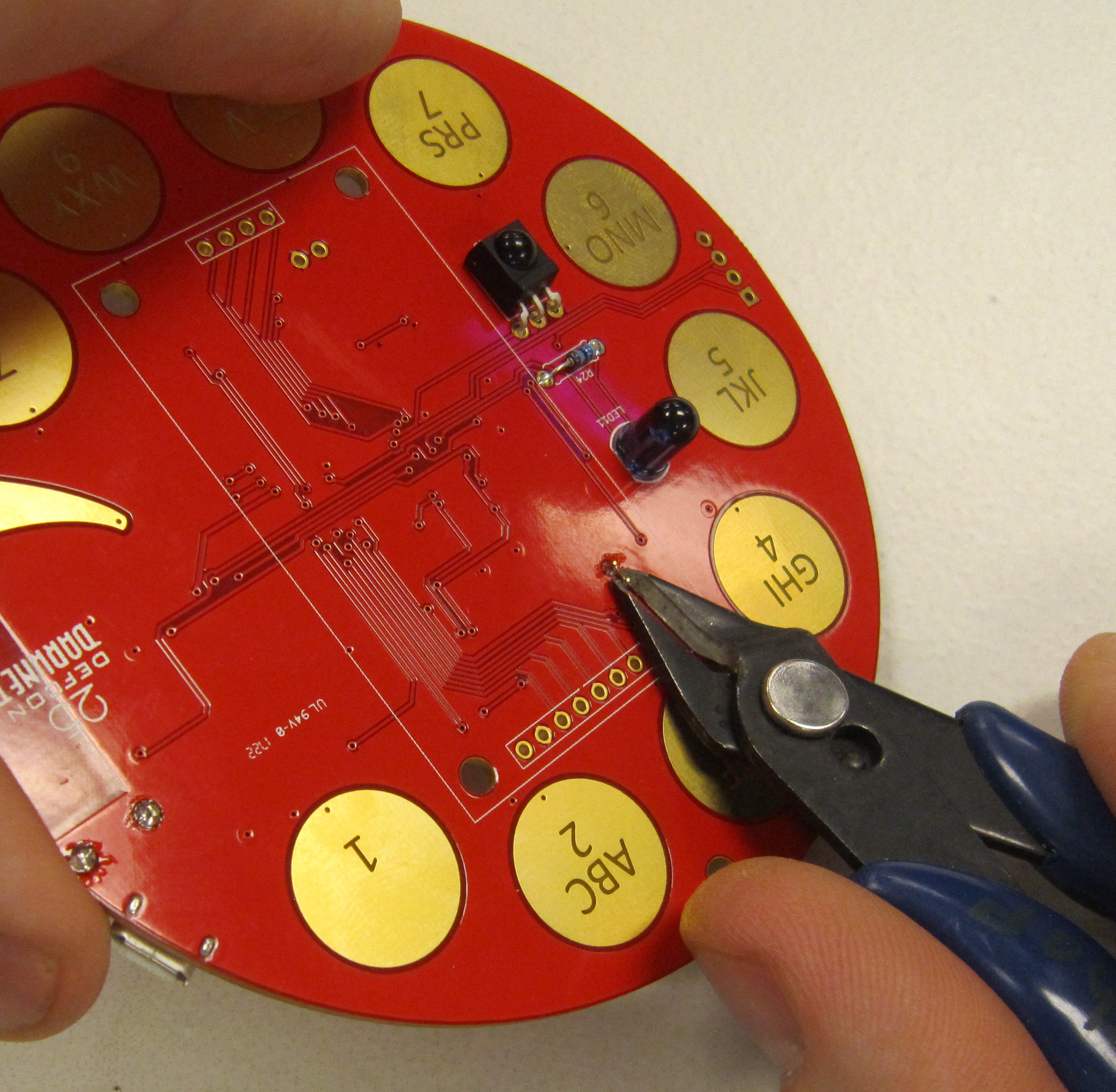
Using flush cutters, trim the resistor leads close to the board. This should be where the component lead meets the solder, as shown here. Excess lead can make unintentional contact with other components and cause shorts, so leads should always be trimmed as close to the board without cutting away the solder joint.
Safety Tip: When cutting component leads, ensure that you are holding the lead when you cut the part to prevent the lead from becoming a projectile. Not doing this can lead to eye injury for yourself or others. You can easily do this by holding a finger tip over the lead as you cut it.
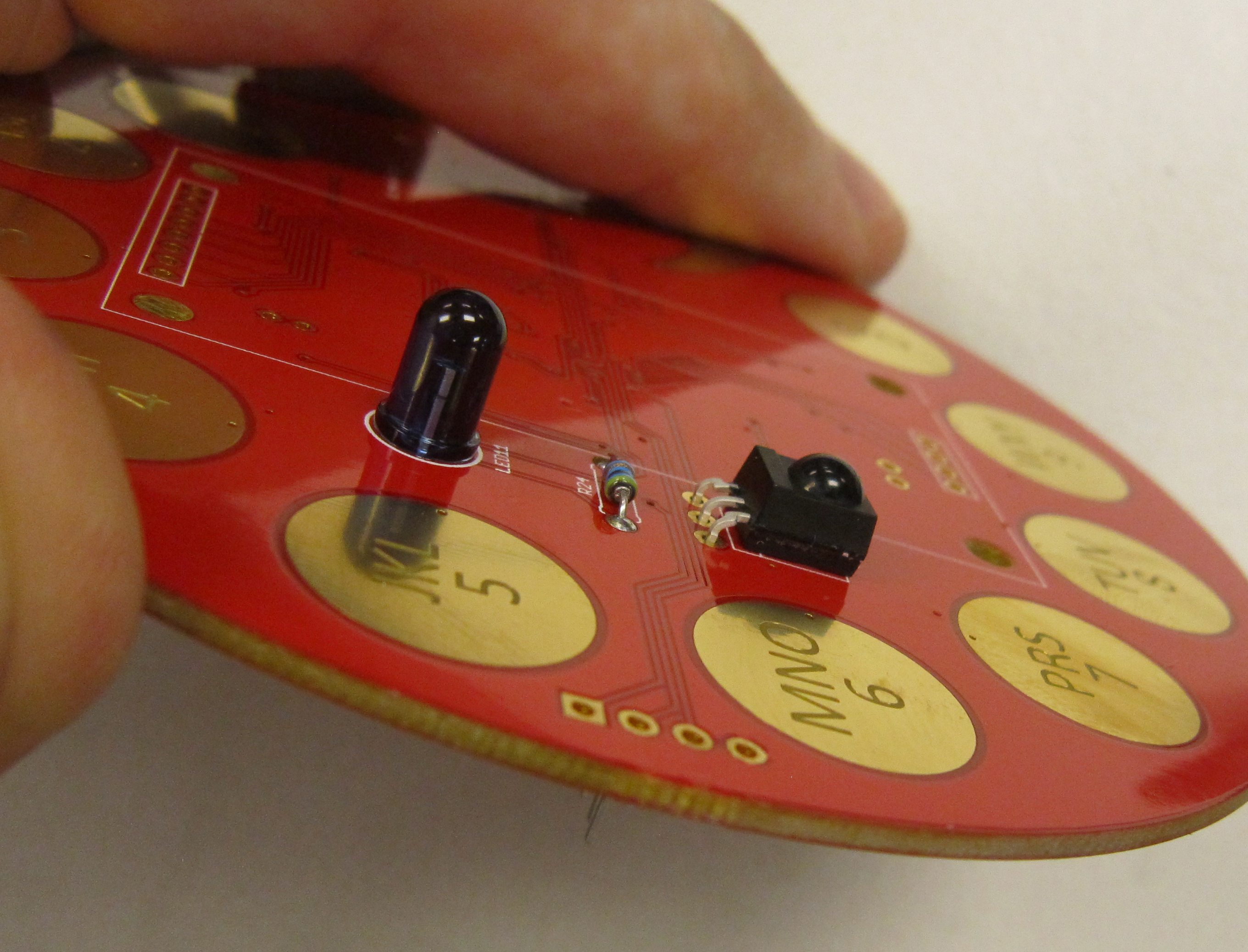
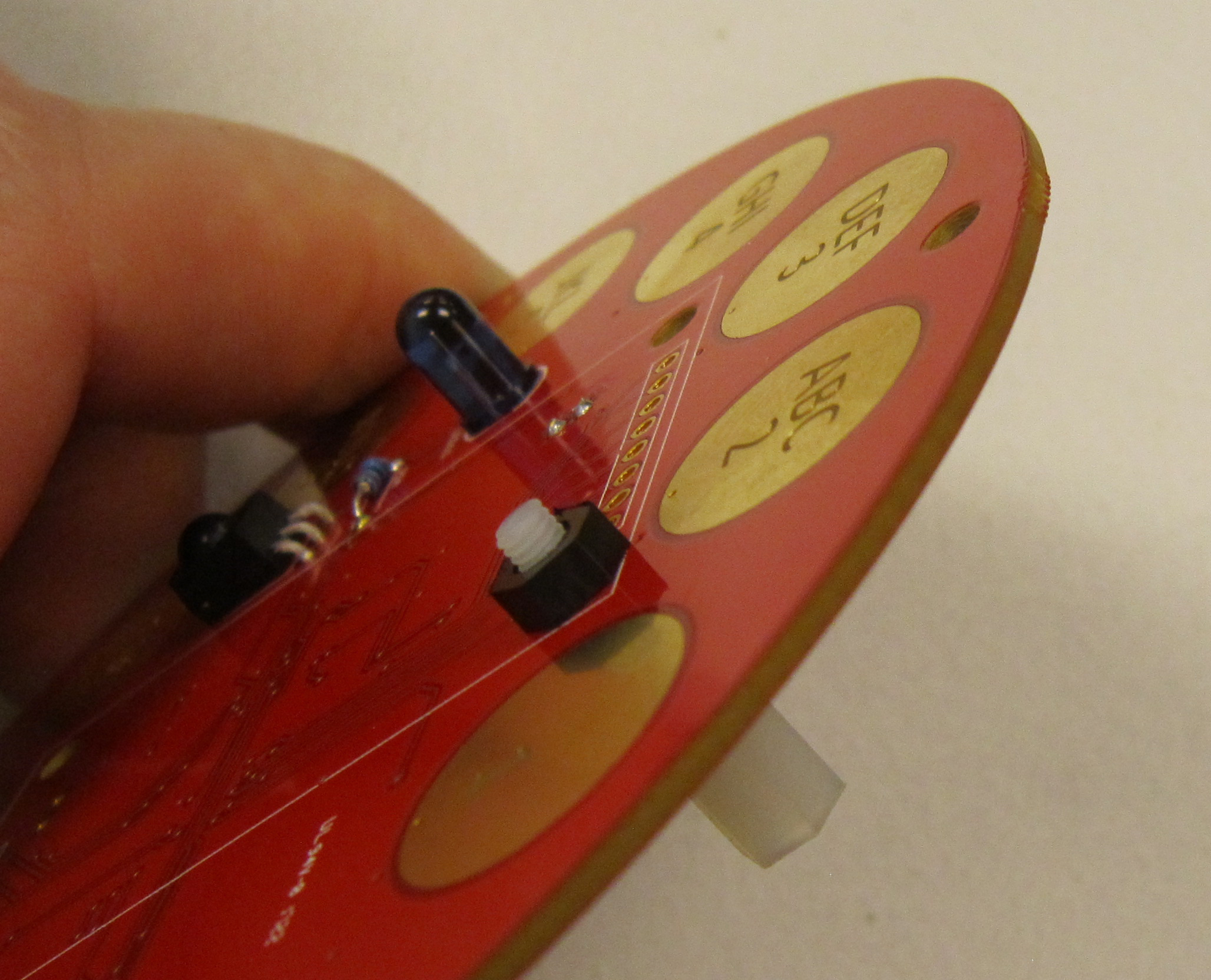
Next we will be installing the infrared LED. LEDs are polarized, and will only work if installed correctly.
The polarity of LEDs can be determined using two methods. The leads of the LED are differing lengths, with the longer of the two leads indicating the Anode, or positive lead.
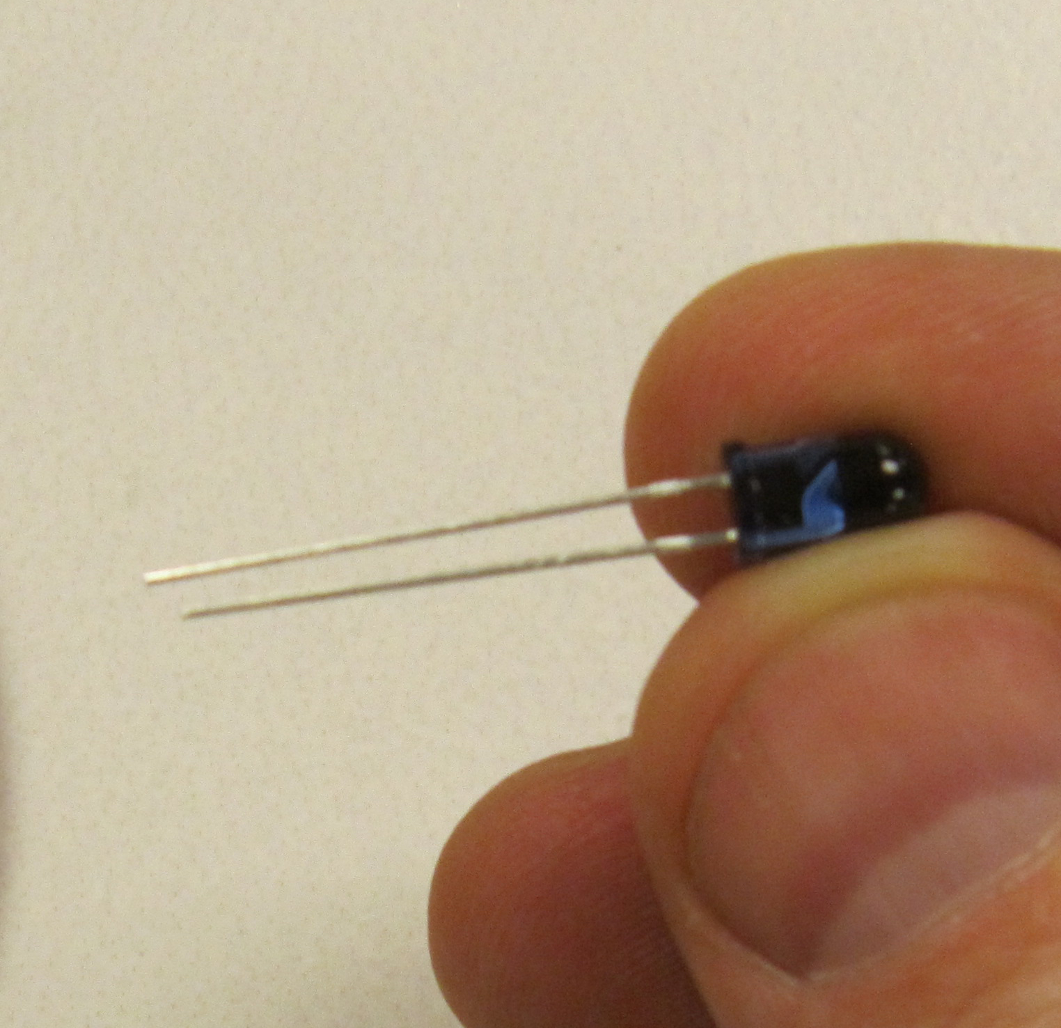
The second method is by determining the flat spot of the LED. This indicates the Cathode, or negative lead.
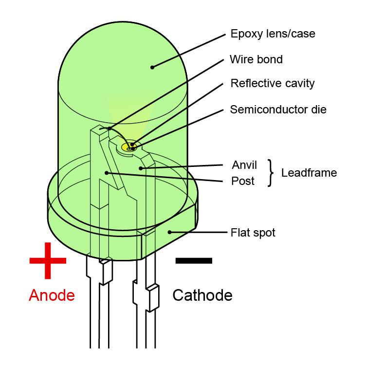
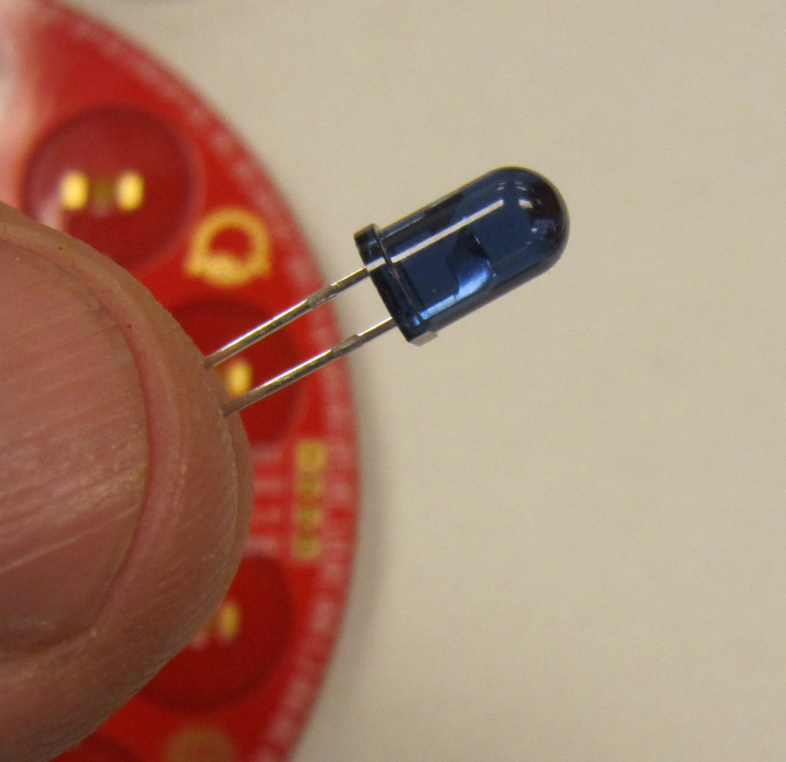
We will be installing the IR LED at LED11.
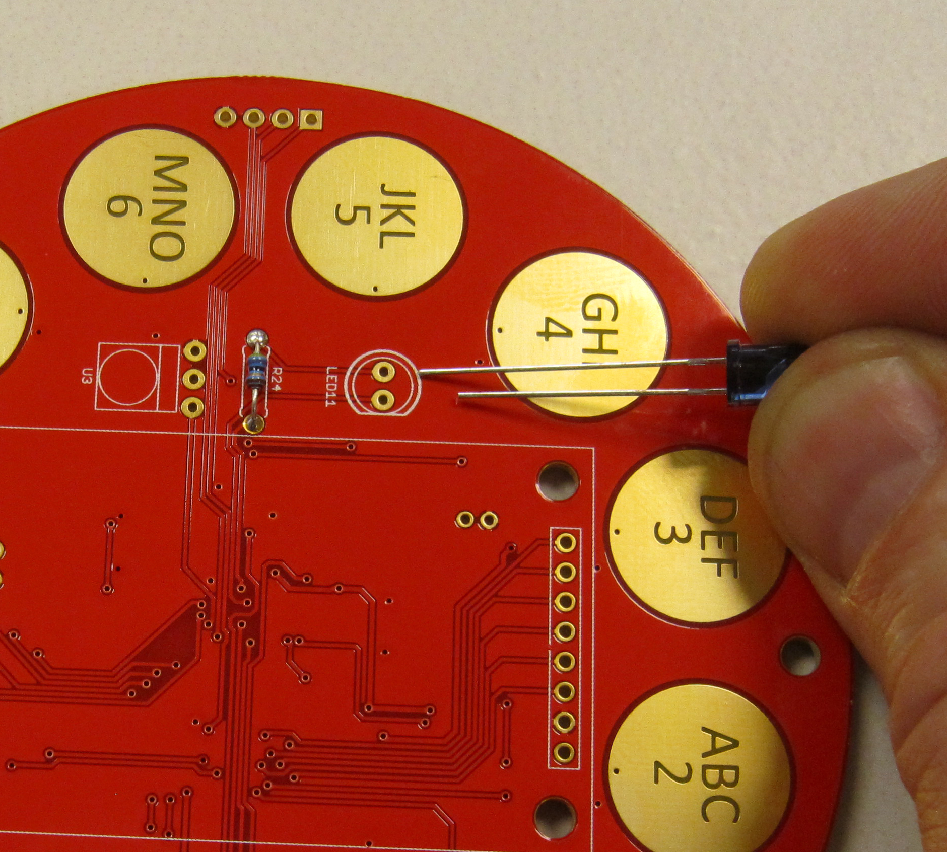
The LED should be flush with the board as shown. Flare the leads out to help keep the LED seated.
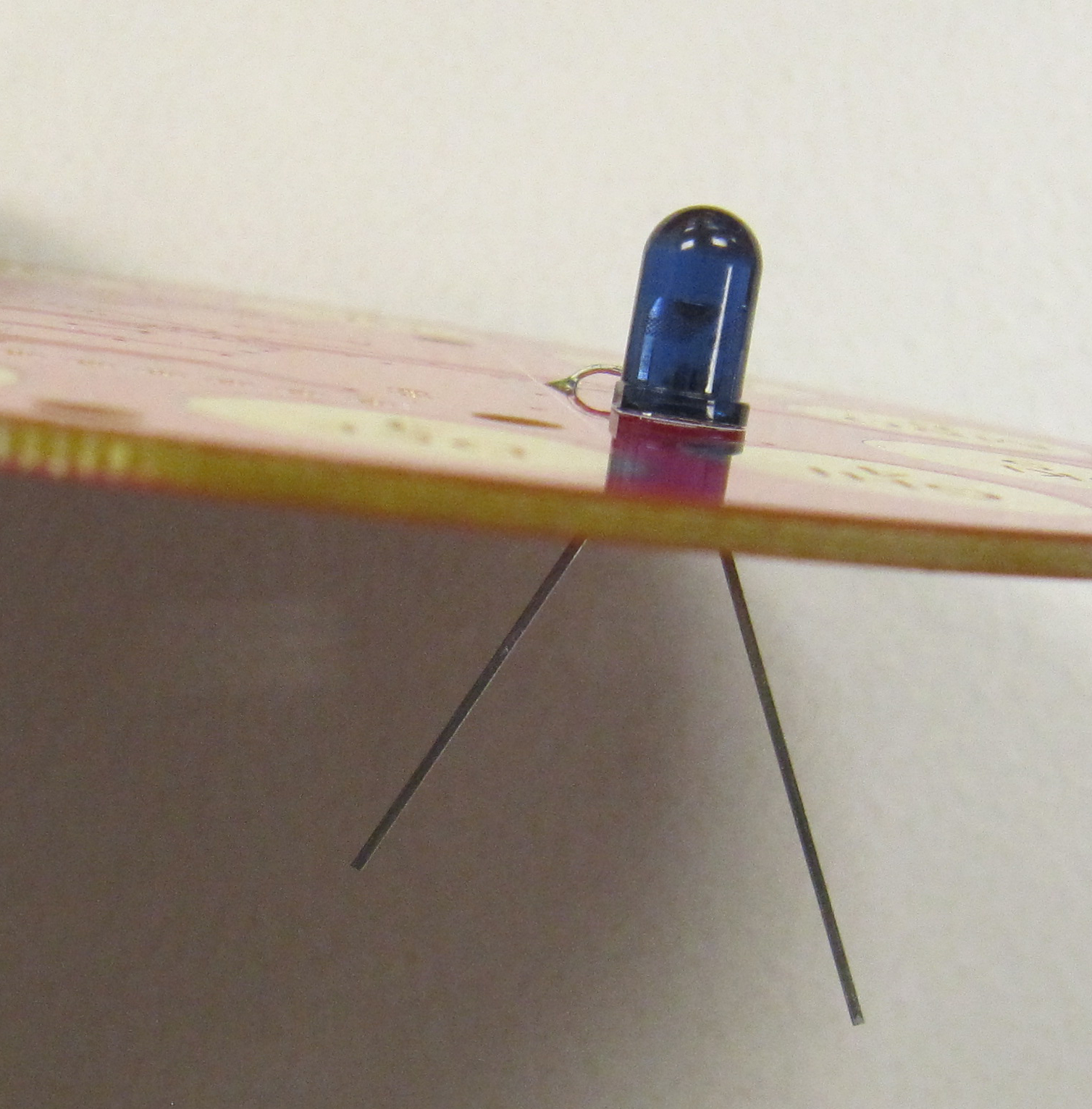
Solder in place, and trim the leads as you did with the resistor.
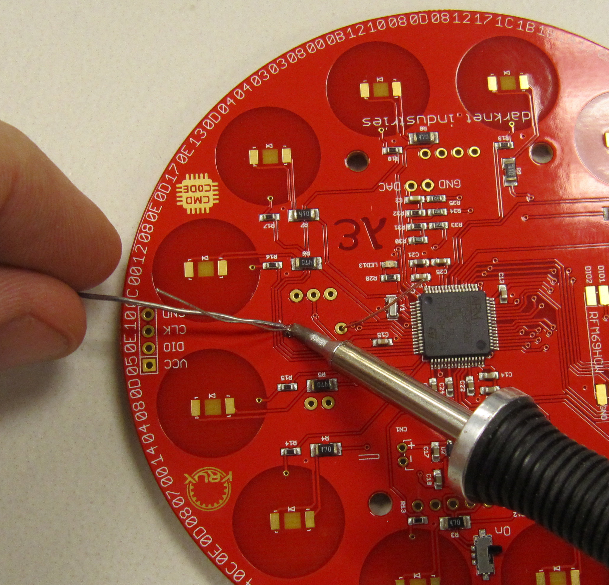
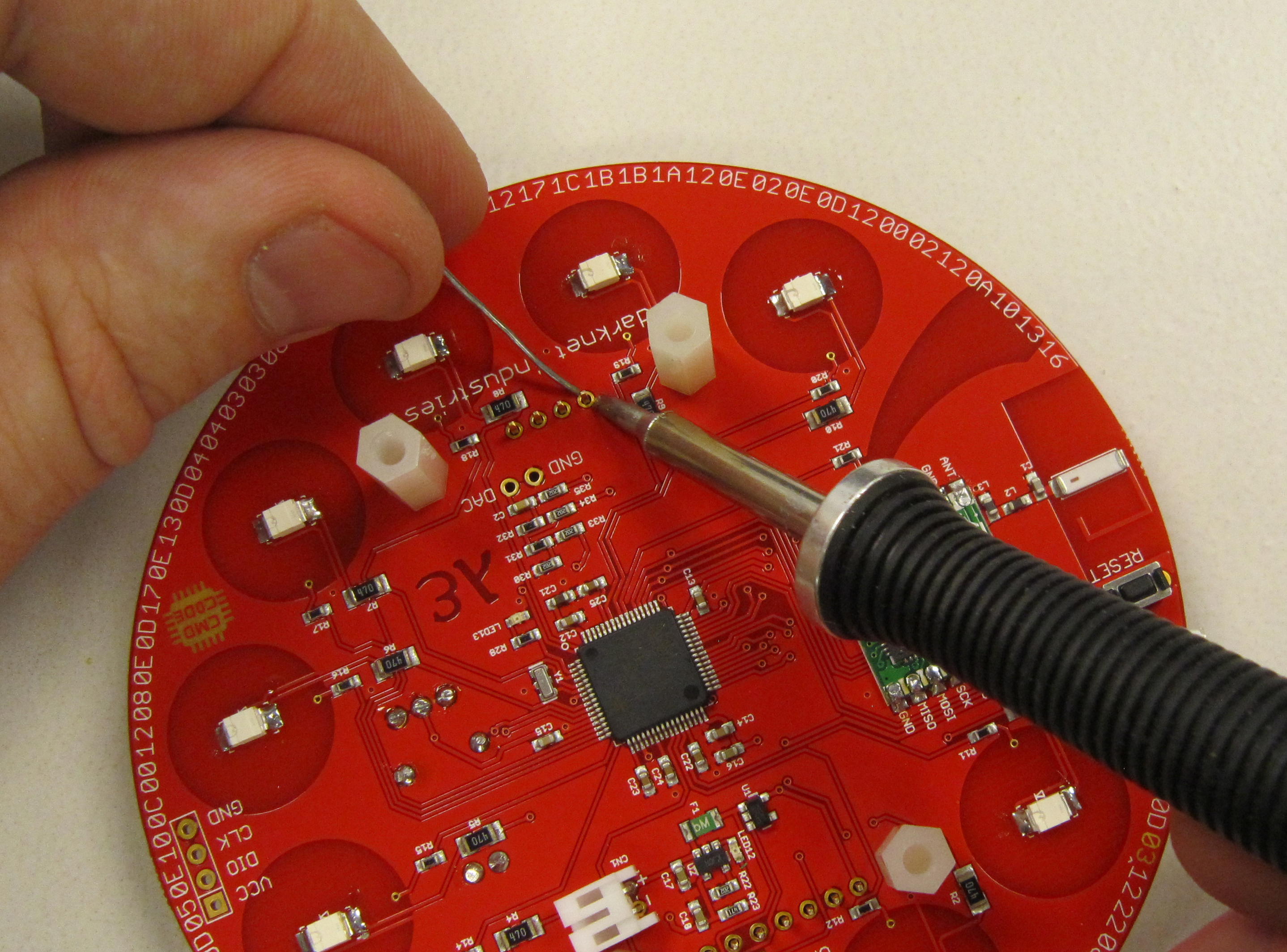
Now we add in the infrared receiver module. This component is polarized, and is installed in U3, so the dome is pointing away from the badge.
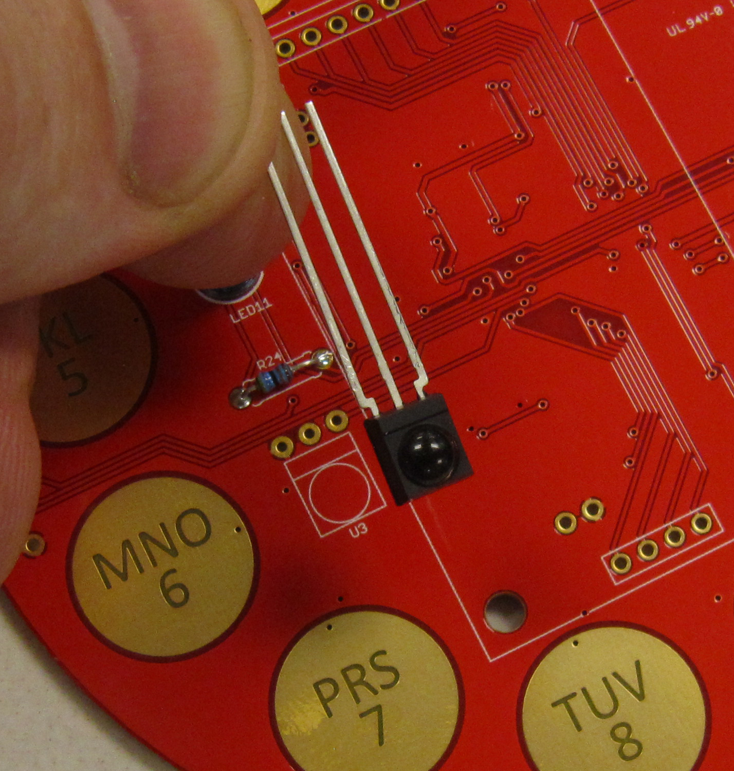
Using needle nose pliers, bend the leads of the IR receiver module as shown. There should be about 1mm of space between the module and the bend.
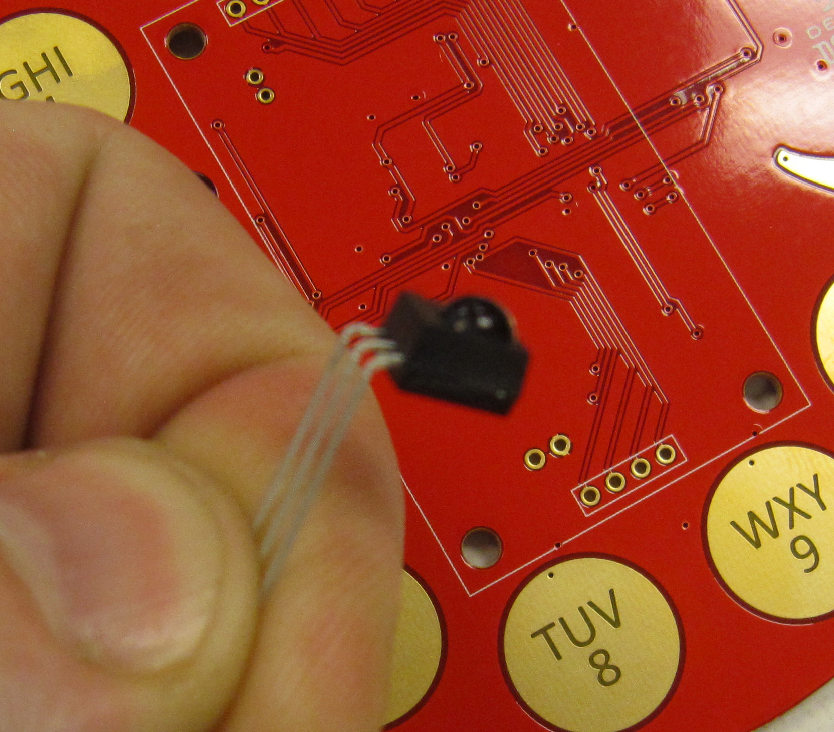
Install in the board, so the IR receiver module lines up with the silk screen, flush to the board. A dab of super-glue can be used to secure the IR receiver to the board if needed.
Solder the middle lead of the module.
Check that the component is still flush with the board. If it needs to be adjusted, reheat the solder and move the part back into place while the solder is molten.
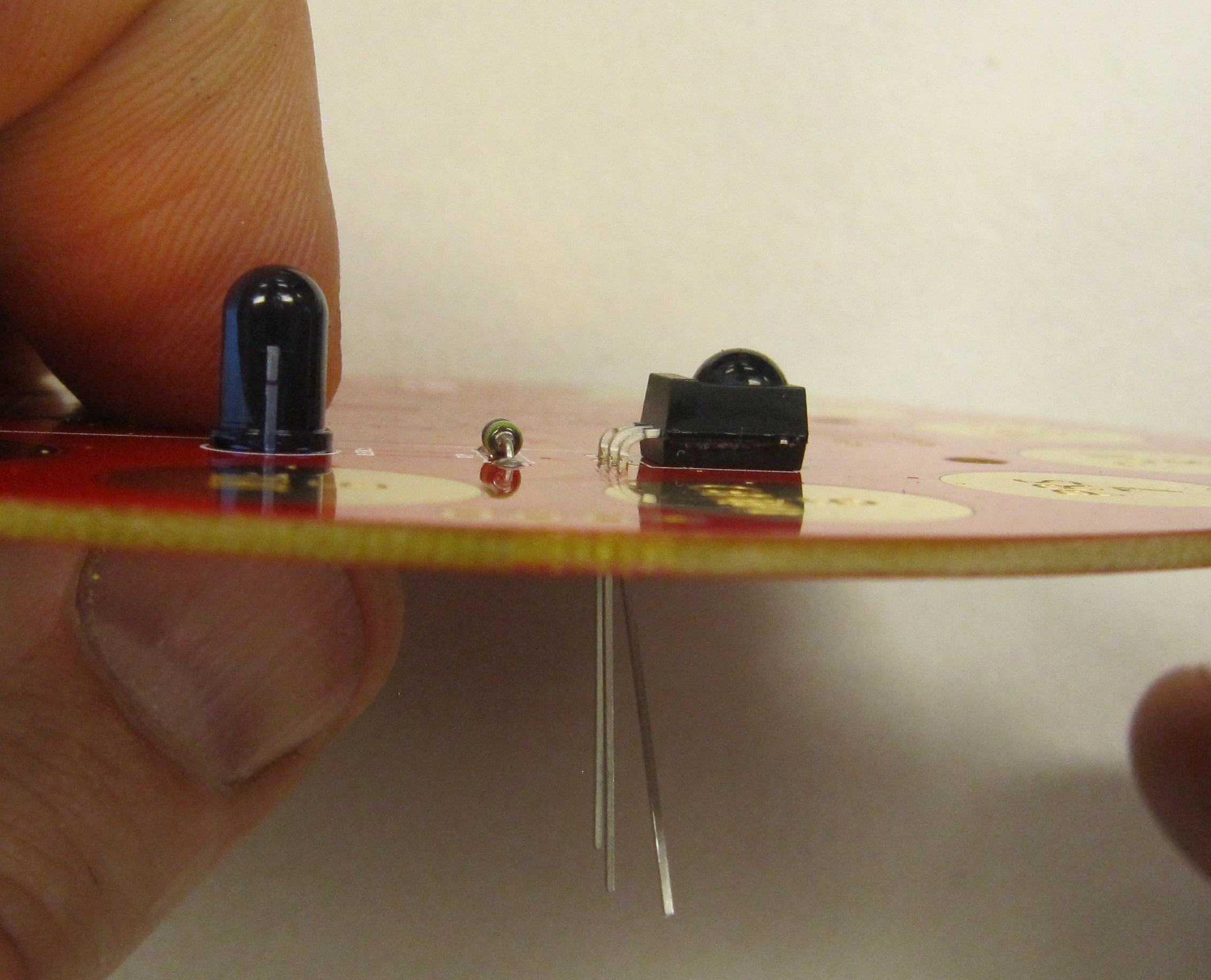
Finally, solder the remaining two leads, and trim flush, as you did with the previous components.
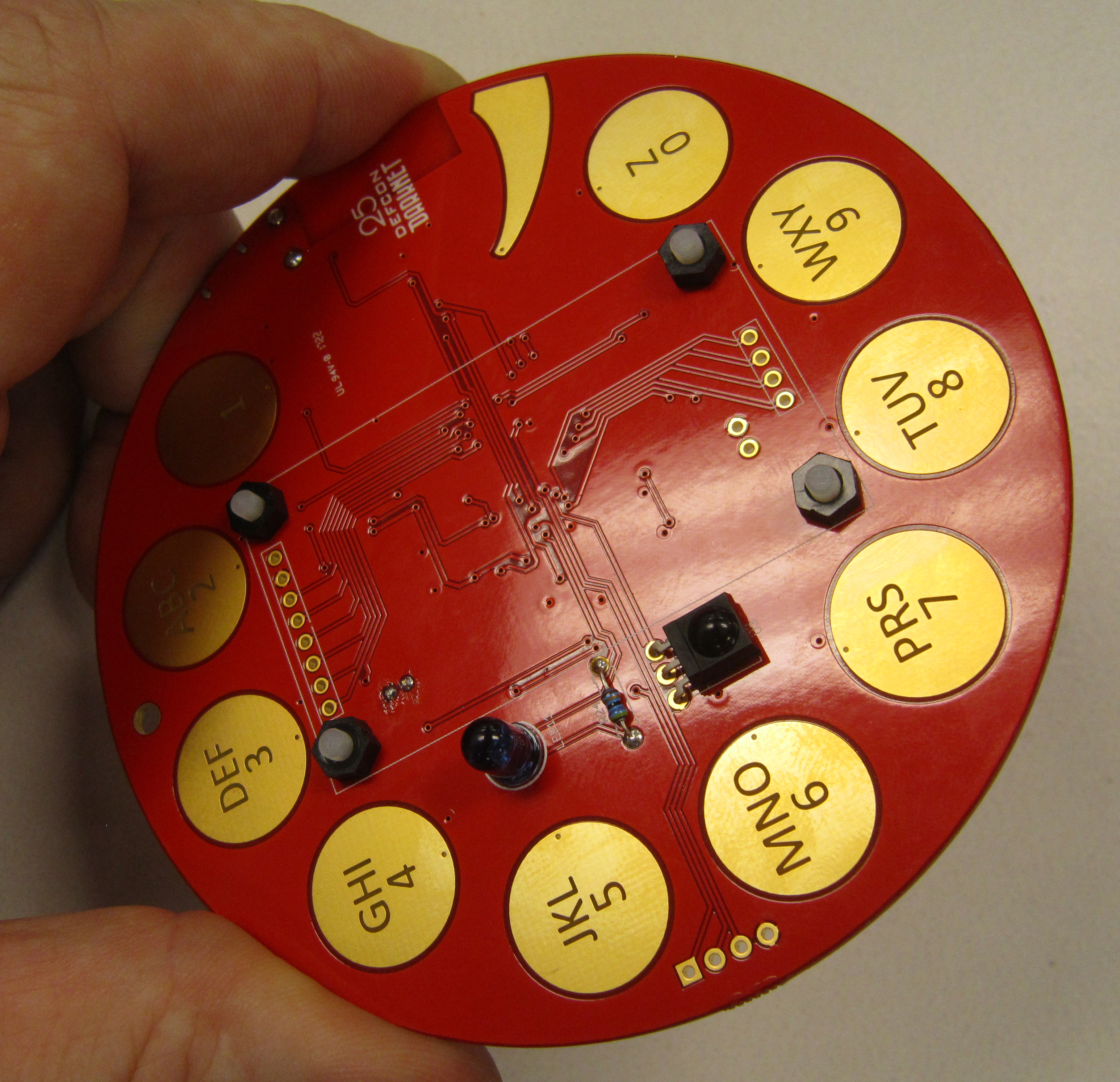
Note the reset switch should be mounted on the back side of the board, opposite the previous components.
Insert the tactile switch in the PCB where reset is indicated. The component leads will snap into place and hold the part while soldering.
On the front side of the board trim the leads flush.
To smooth the surface, use the soldering iron to re-melt the solder on the trimmed leads. Adding a very very slight amount if necessary. As this is the face the the badge you want a nice clean surface.
Next we will install the JST connector which our Lipo battery will later connect to. As this is a power component it is very much polarized.
As shown, install the JST connector so when looking at the back of the badge, the connector points toward the right, and the connector can sit flush with the board at CN1.
Solder the connector in place, and trim the leads flush.
If necessary, additional mechanical strength can be added by ensuring that the pads and leads of the connector are soldered on the back side of the board as well. This is tricky to solder and requires a fine point soldering iron and finesse so as to not damage the plastic components of the connector.
Note: care should always be taken when ever inserting or removing the battery leads from the connector.
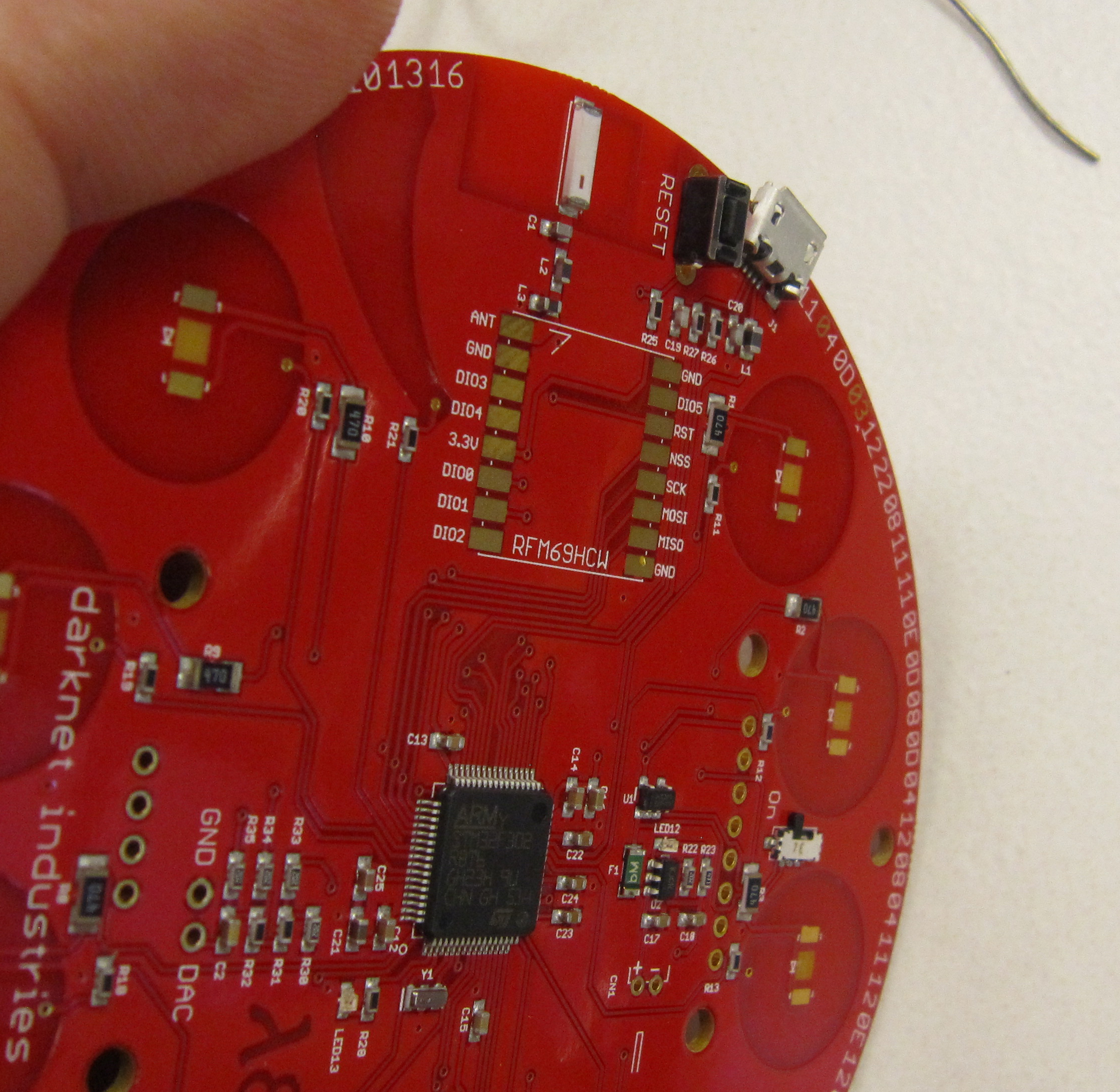
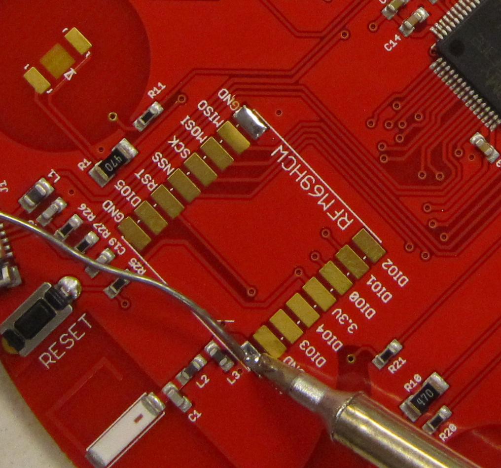
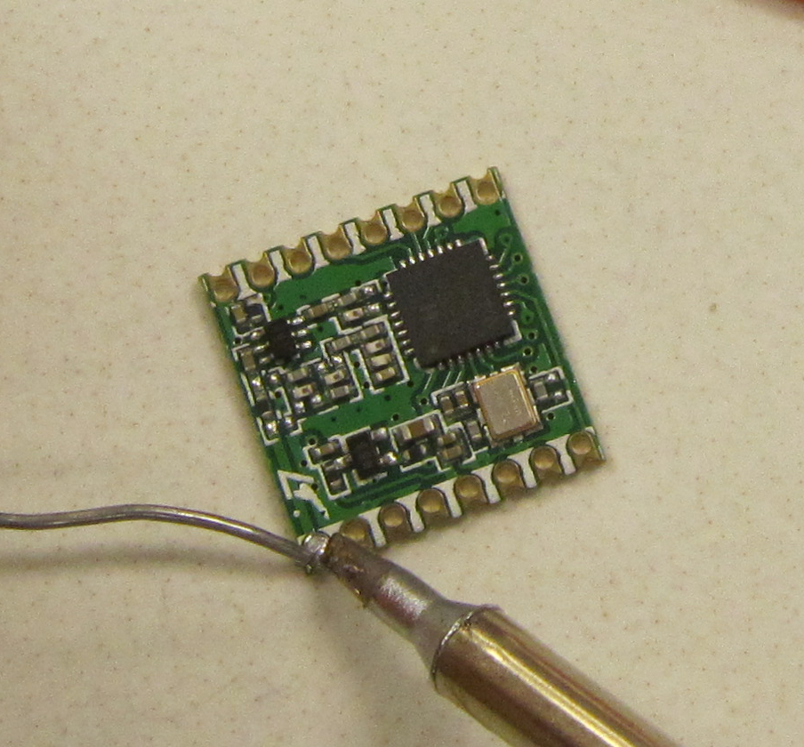
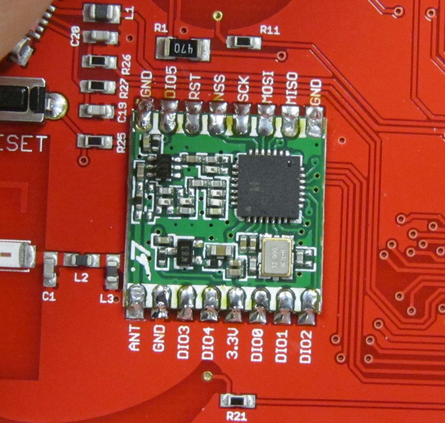
It's surface mount soldering time. While surface mount soldering may seem intimidating, using the method shown, the parts in this kit can be soldered using conventional soldering tools. We will start with the radio module. While it is more involved to solder, it is also a much larger part, so it's better to start out with.
To solder surface mount parts using hand soldering tools, the easiest method I have found is to tin one pad, or for larger components, two pads. Next position the part, and melt the solder on the tinned pad or pads to anchor the part into position, then solder the remaining leads. This allows you to reposition the part when there is only one lead soldered by reheating the solder and adjusting while the solder is molten.
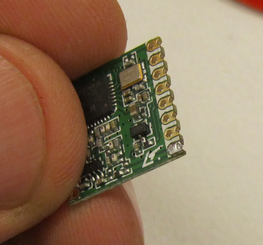
The radio module must be installed in the correct orientation. There is a mark on the module and a mark on the PCB where the antenna pin is located.
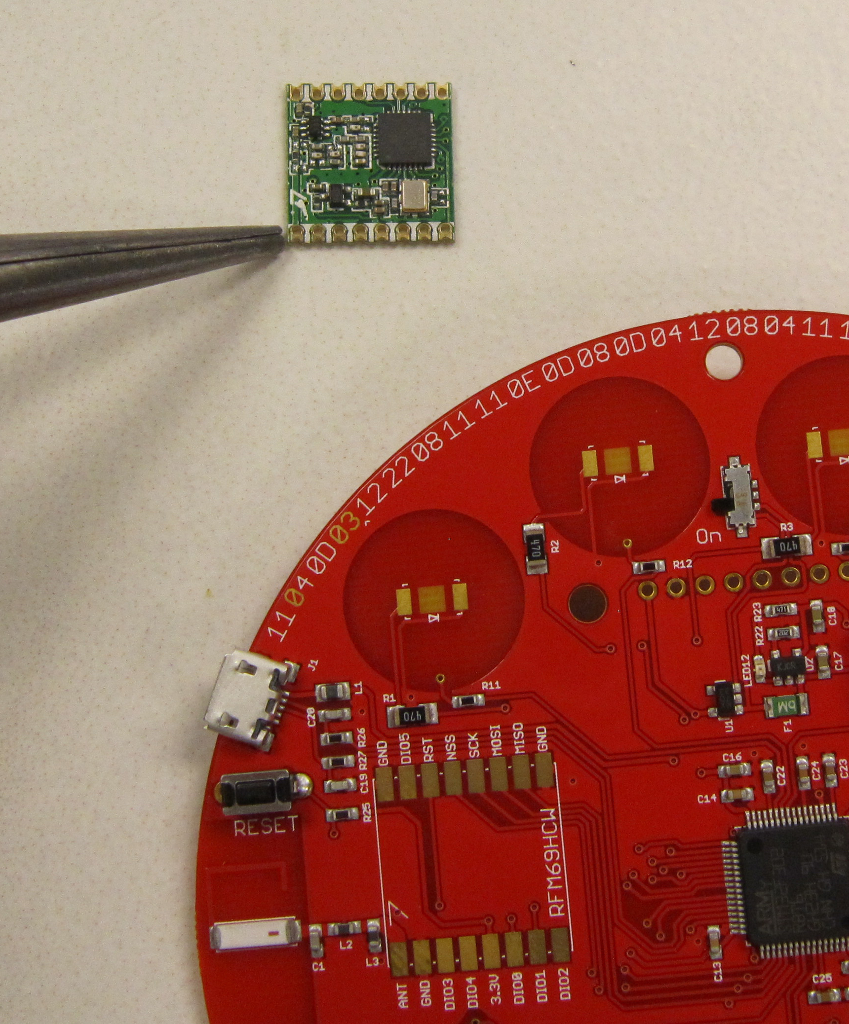
Start by tinning the GND pad in the corner by MISO. Do this by heating the pad, and feeding in a little solder. There should be a slight dome of solder when you are finished. If there is too much solder use solder wick to remove the excess.
Next tin the pad marked ANT, diagonal to the first pad.
Next we will tin the corresponding pads on the radio module PCB. Heat the antenna pad, and apply a small amount of solder. The antenna pad is marked with a little angled symbol.
Now tin the ground pin opposite the antenna pin.
Your tinned pad should look similar to this.
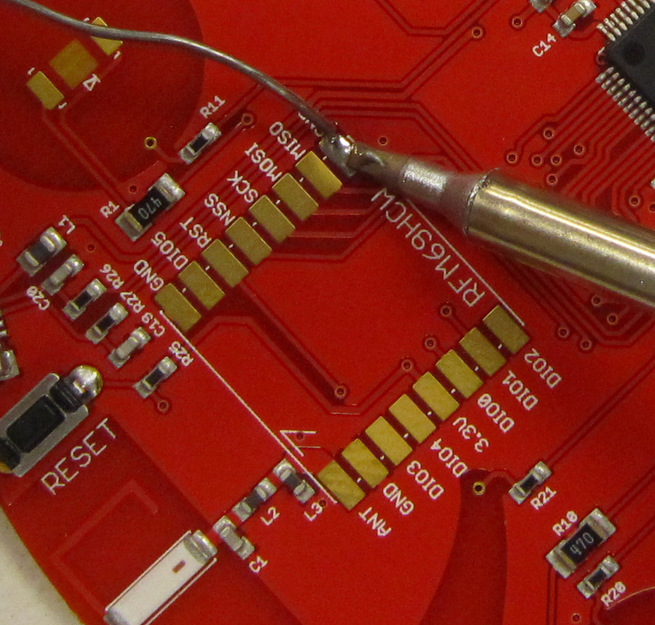
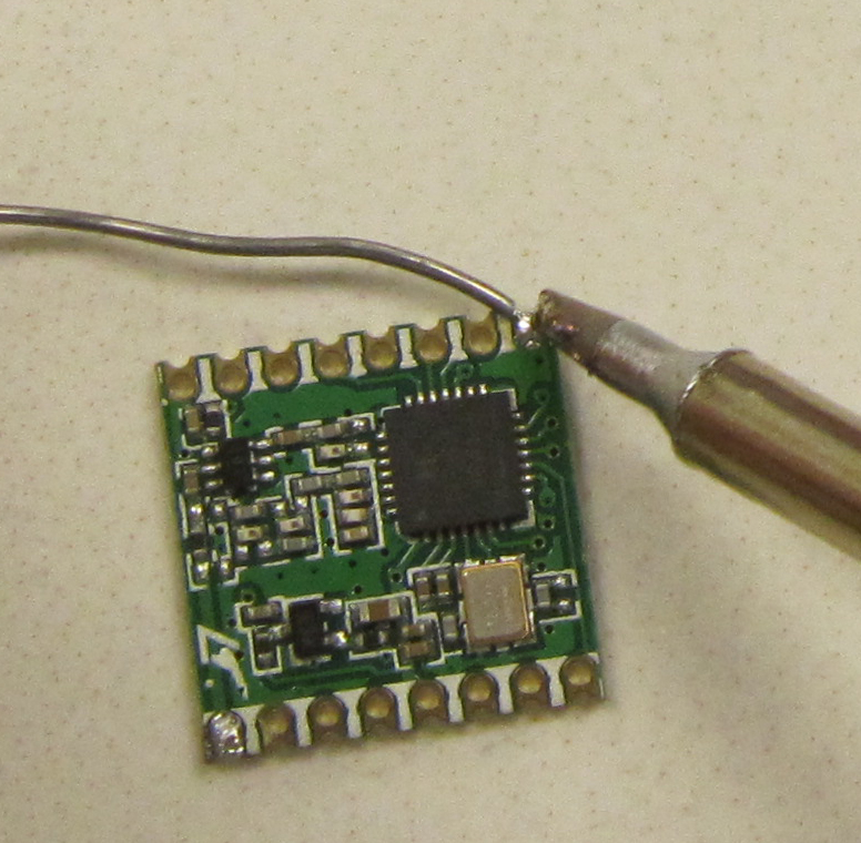
Center the radio module on the PCB, being certain that the antenna pin matches the antenna pad, and the ground pin matches the ground pad. The pads should line up, and there should be equal amounts of pad exposed on both sides of the radio module. In other words as centered as centered can be. Once your part is in place, we will anchor it by heating the ground pin. Your soldering iron tip should touch both the ground pad on the PCB, and the ground pad on the radio module. Apply gentle pressure to the module, and it should drop into place. Remove the iron, and allow the board a few seconds to cool before releasing.
Ensure that the radio module has not shifted and that everything is aligned. If it is not aligned, use the soldering iron to melt the solder again, and only then reposition the radio module. Failure to do this can destroy the radio module and damage the pad on the badge.
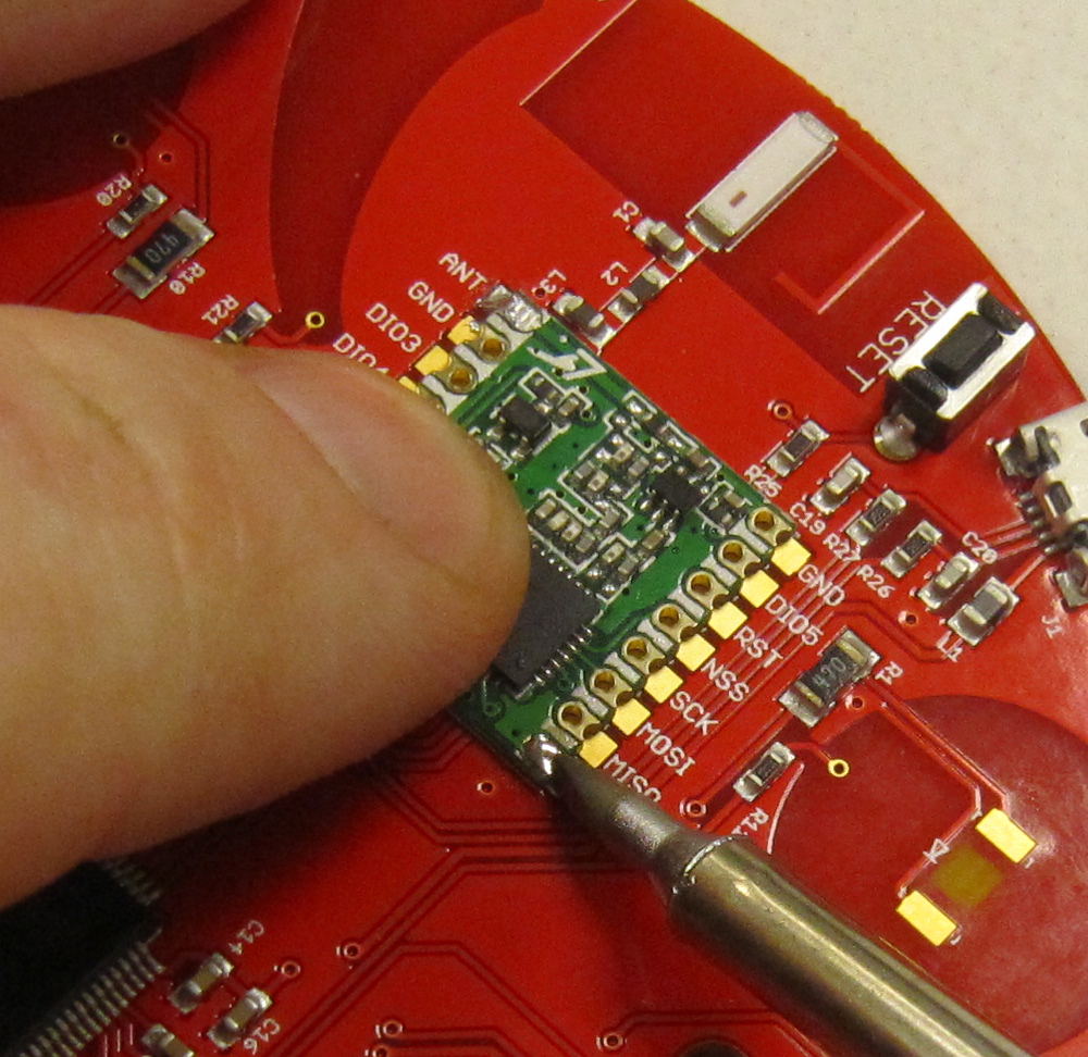
Repeat this step for the antenna pad. Holding the part in place, and heating both the pad on the badge, and the pad on the radio module. Inspect the position of the radio module again to ensure that it is aligned correctly.
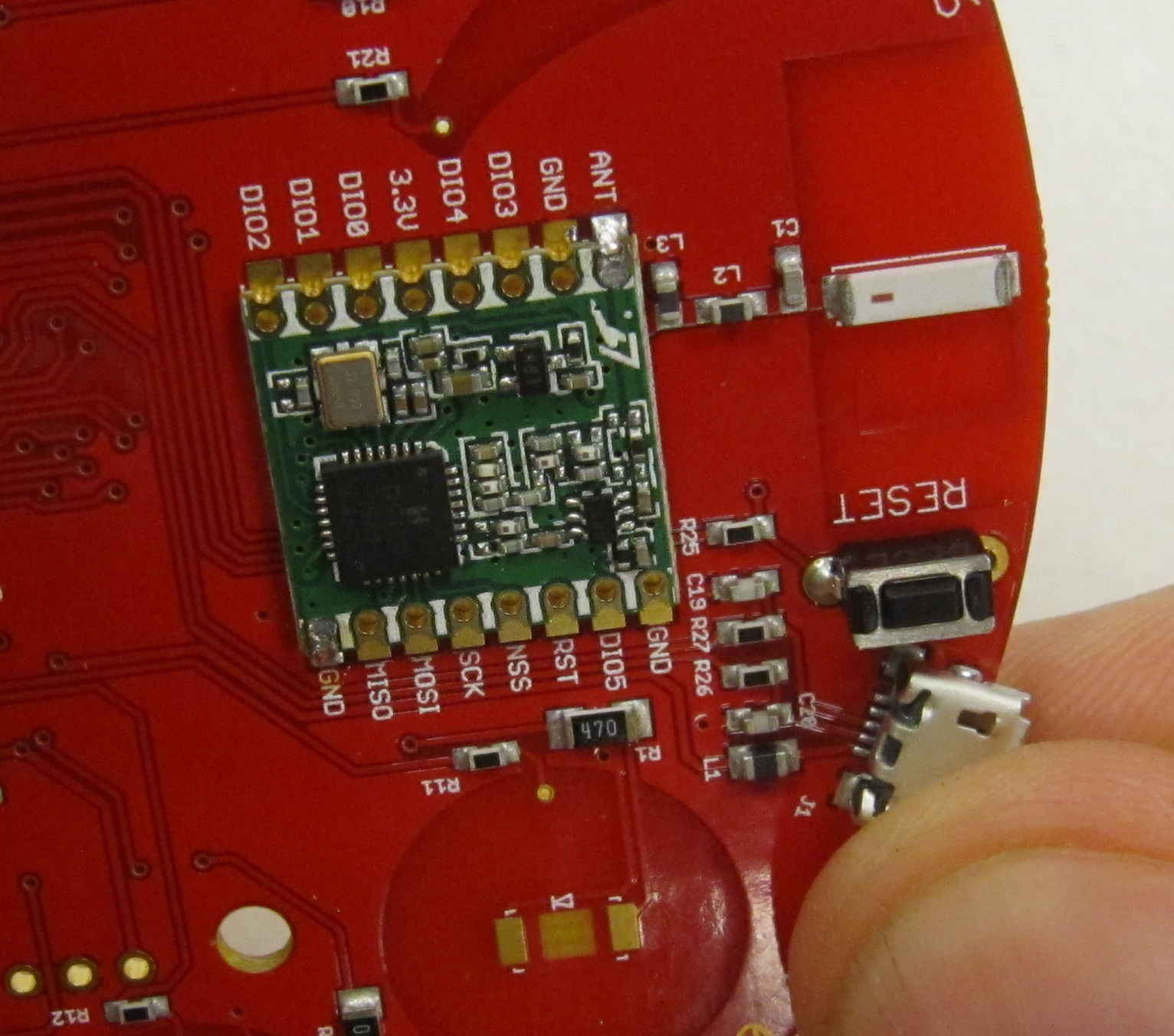
Finally solder the remaining pins by placing the soldering iron tip so it is heating both the pad on the badge and the pad on the radio module, and adding a small amount of solder.
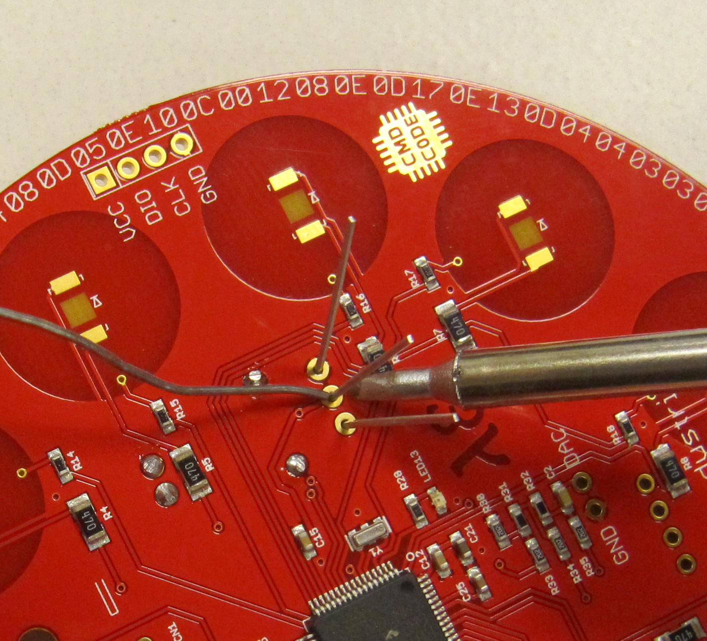
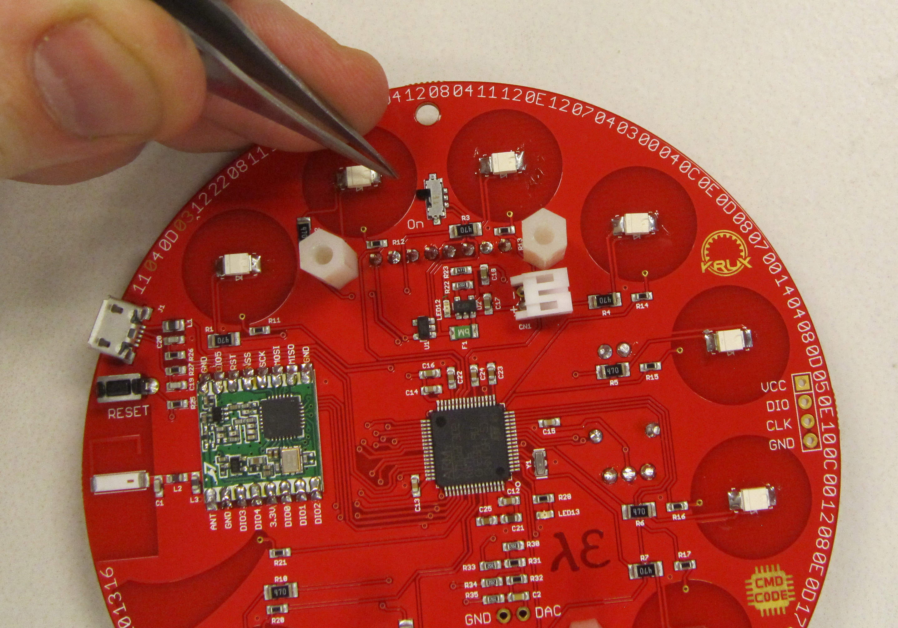
The next step is to solder the ten surface mount LEDs. The LEDs are small parts, and are easily lost. Care should be taken when opening the tape strip that contains the LEDs
The LEDs are polarized, and will only work if installed in the correct orientation. On the PCB is the electrical symbol for a diode.

The Cathode on the LEDs is indicated by a dimple on the top surface. On this badge, the cathode will be toward the right on all the LEDs.
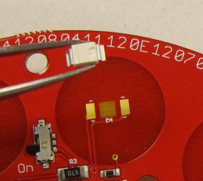
Start by tinning one of the two pads.
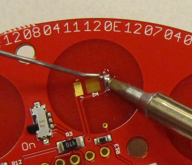
Next, using teasers pick up one LED, and guide it into place, using the soldering iron to heat the pad which was previously tinned. The LED should be centered on the pad.
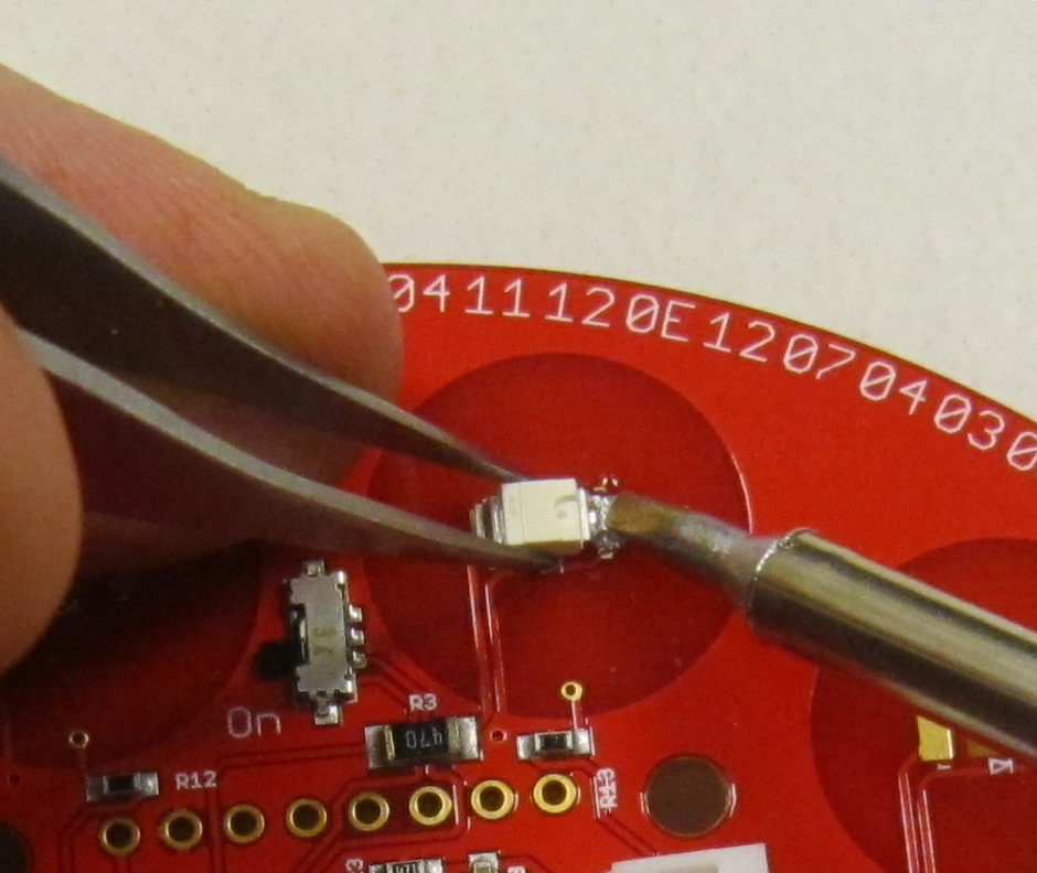
Next heat the second pad, and LED lead, and add solder.
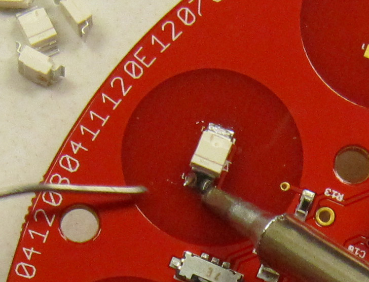
Finally add a very small amount of solder to the first pad to ensure a good connection.
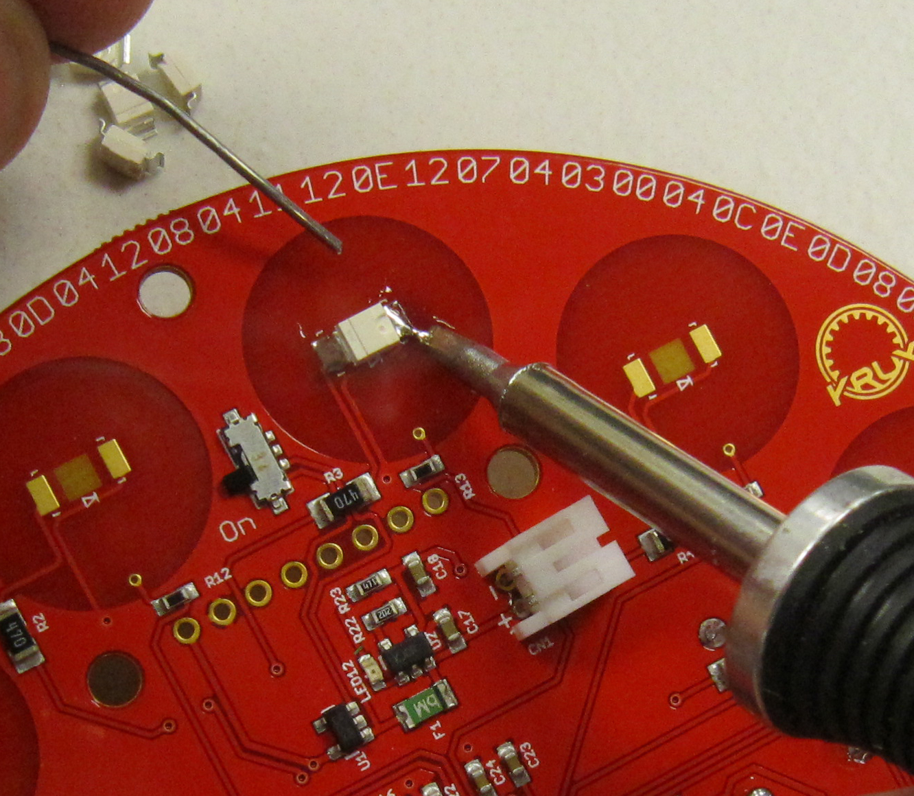
Your finished LEDs should look like the following photo.
This step is best when done before adding the LCD module.
This kit uses a pieces of acrylic which acts as the battery holder for the Lipo battery. It both protects the battery, but also ensures that you are able to remove the battery from the badge if needed. Such as hacking to the badge to do new and interesting things.
Using the provided 3mm nuts and stand offs, install so that the nut is on the front of the badge as shown.
Repeat for the remaining stand offs.
Note: Do not use the screws here. As the display module will block access to the screws in the next step.
The display module is mechanically held in place using the module's eight pin header, and an additional four pin header. This header also is used for the SD card adapter on the back of the display.
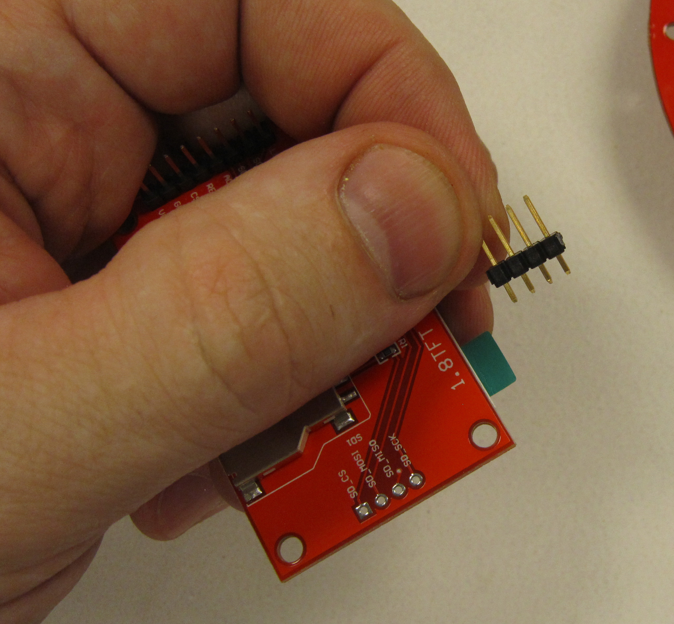
Install the header as shown.
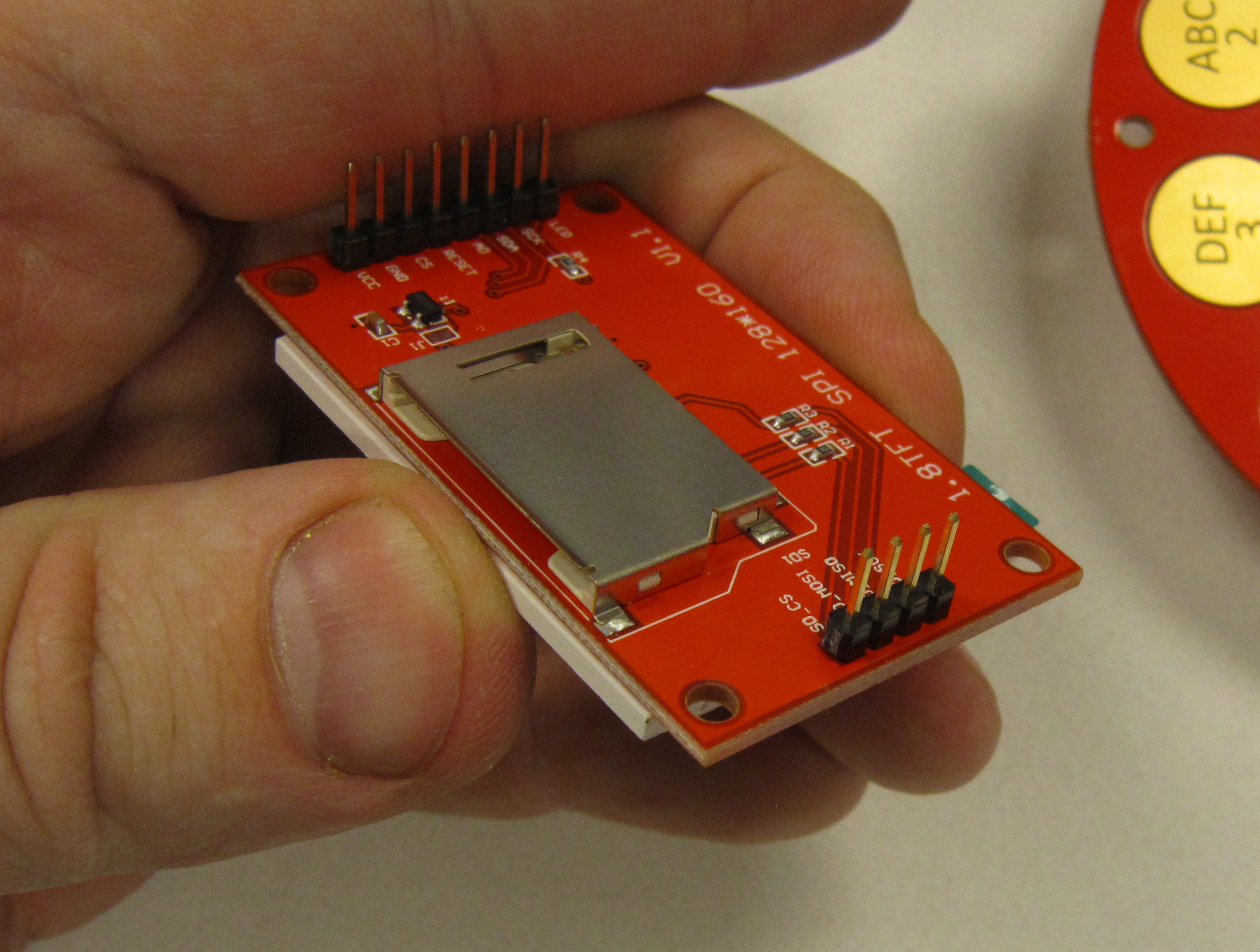
Solder the four pin header to the display module.
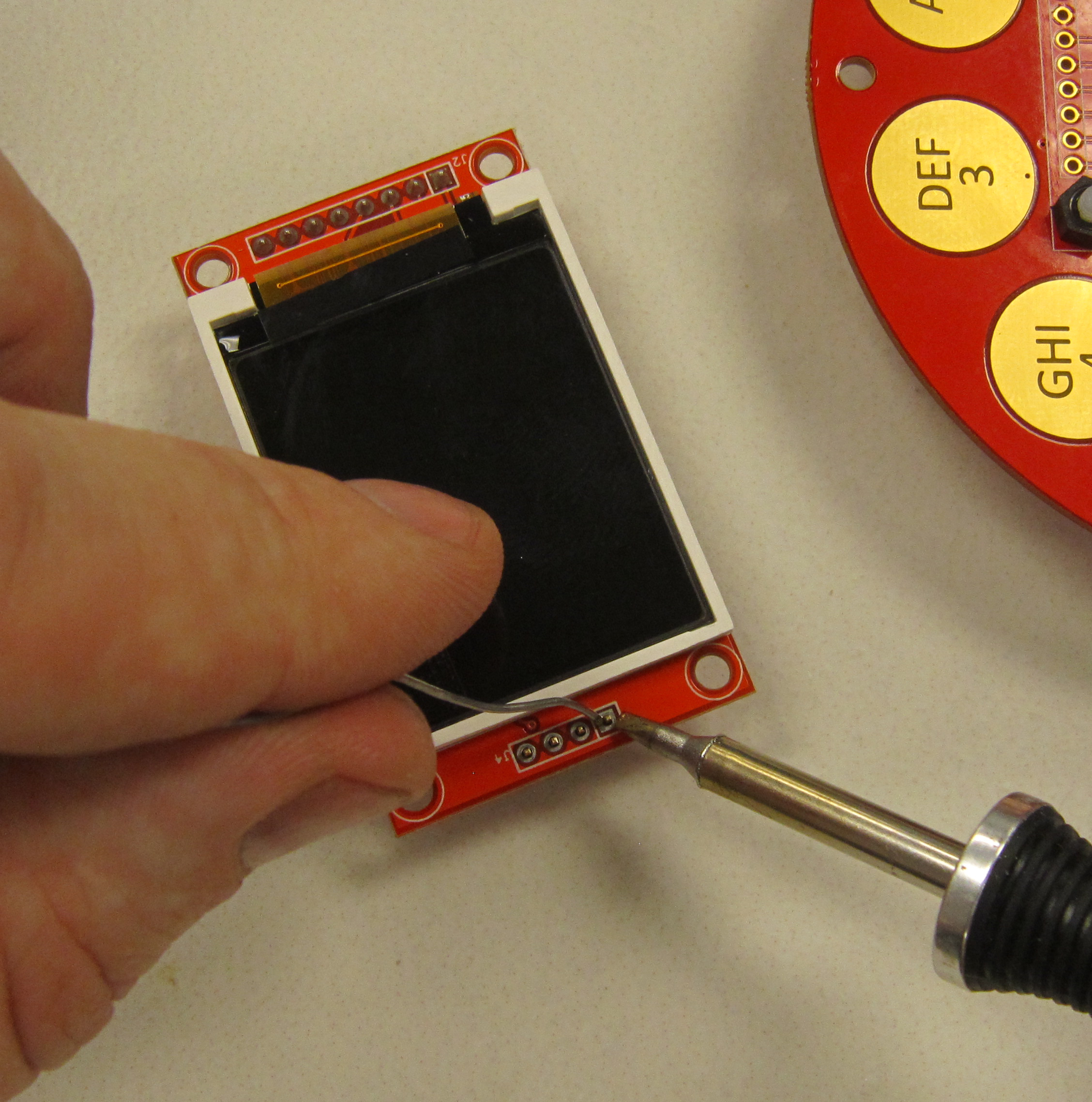
Next attache the display module to the badge.
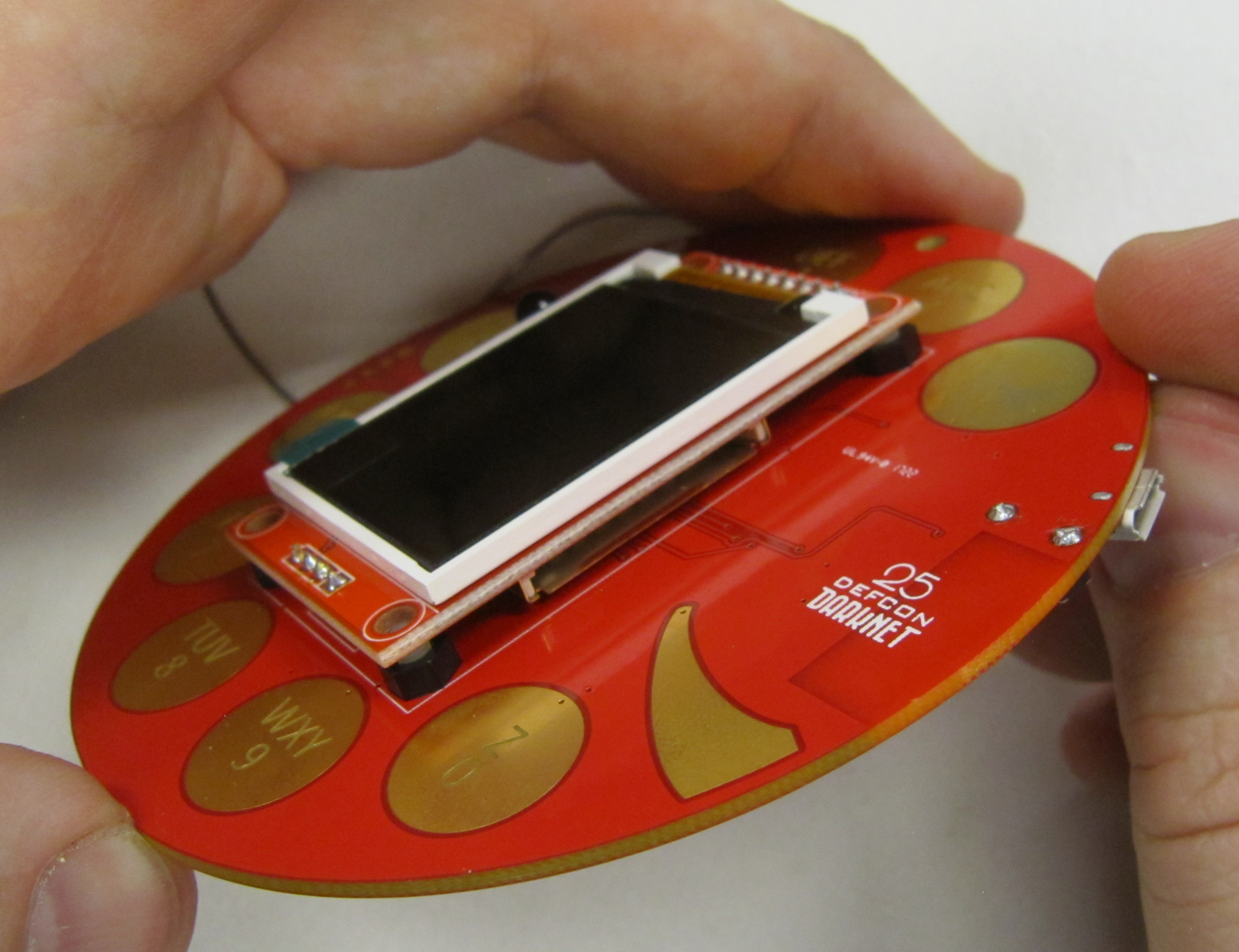
There should be space between the SD card slot and the badge. Minimum is the thickness of one business card. Shown is resting on the stand off screws.
Solder all the headers in place.
Note: Be careful not to melt the stand offs.
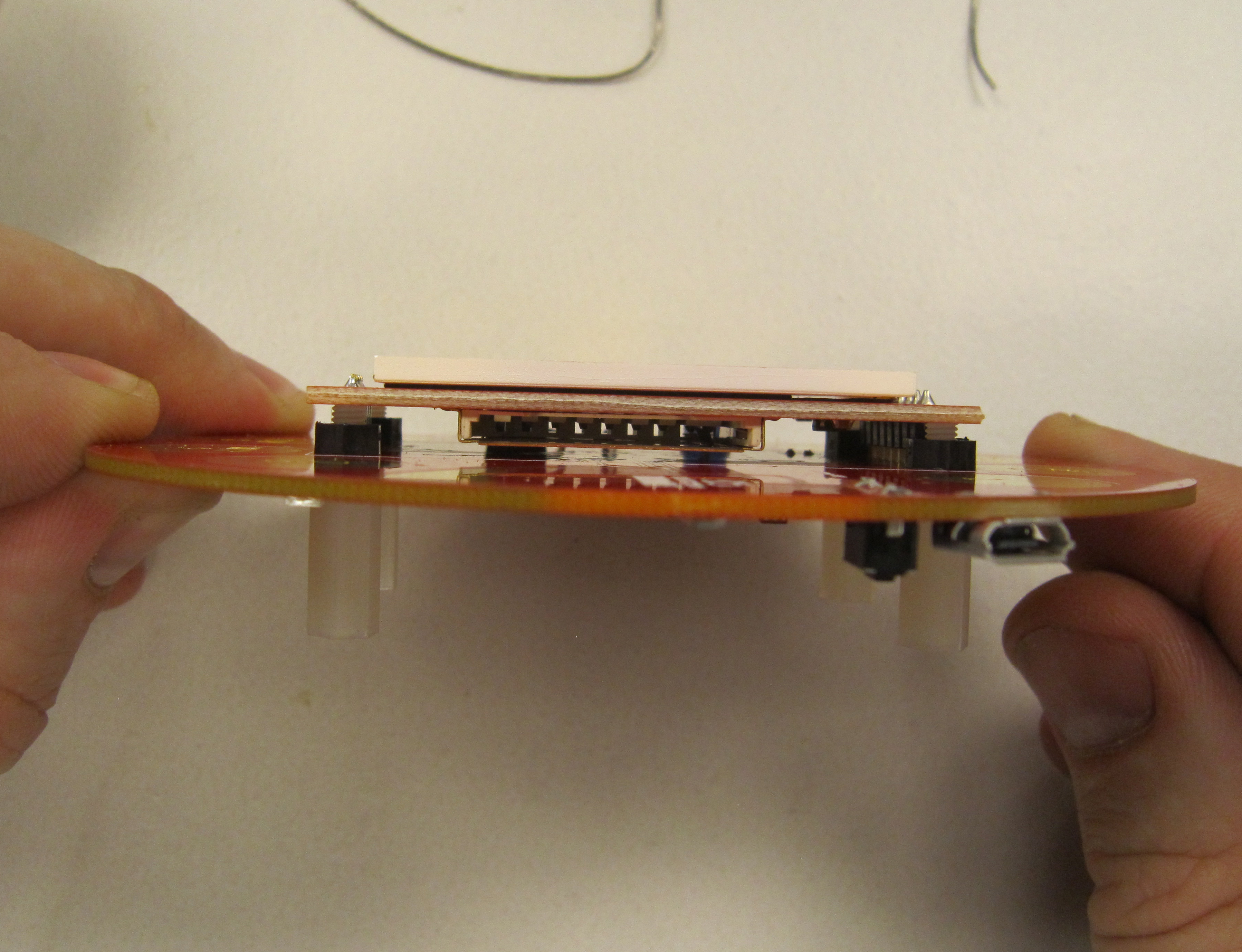
It is not necessary to trim the header leads, as they are protected by the acrylic backing.
The power switches came from the board manufacturer set to on by default. Before proceeding, set the switch to the off position, toward the lanyard hole.
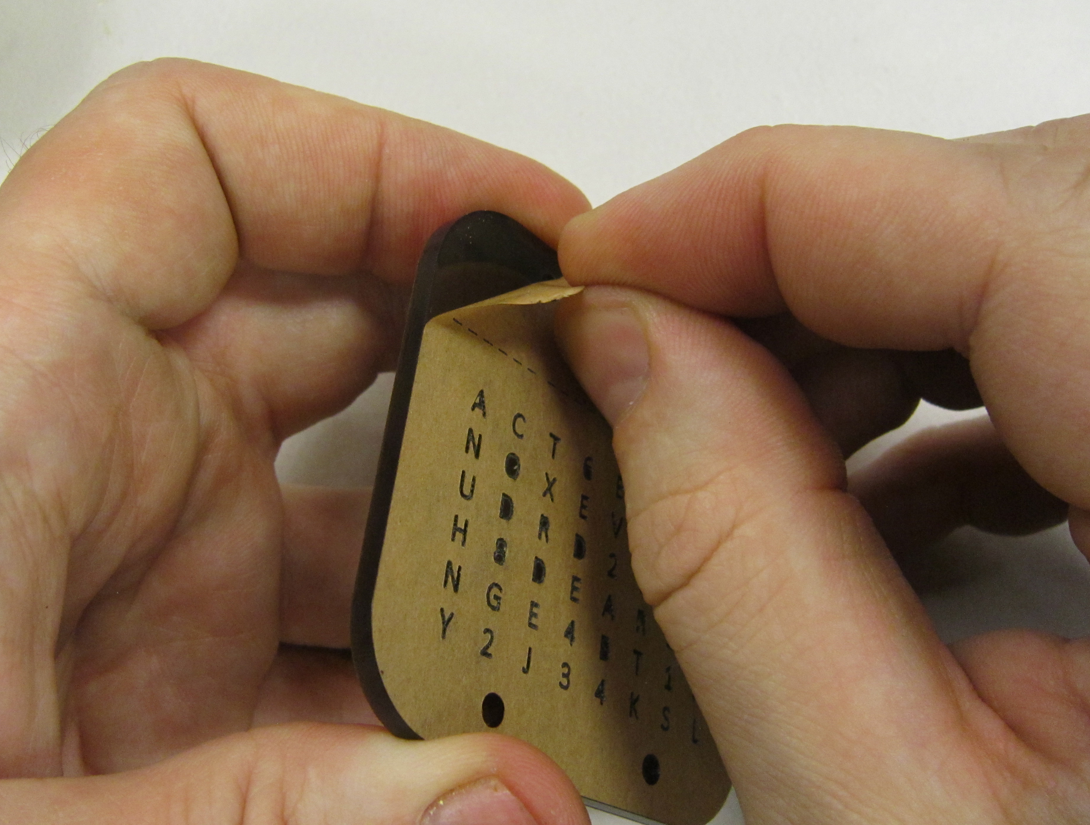
 Next, remove the paper backing from the from the acrylic.
Pro-tip: To avoid getting the glue from the backing on the acrylic, use a finger nail to remove the inside of all letters and numbers which have a center bit, such as A, 0, 4, e, 8, 6, 9, P, etc..
Remove the paper backing on both sides of the acrylic.
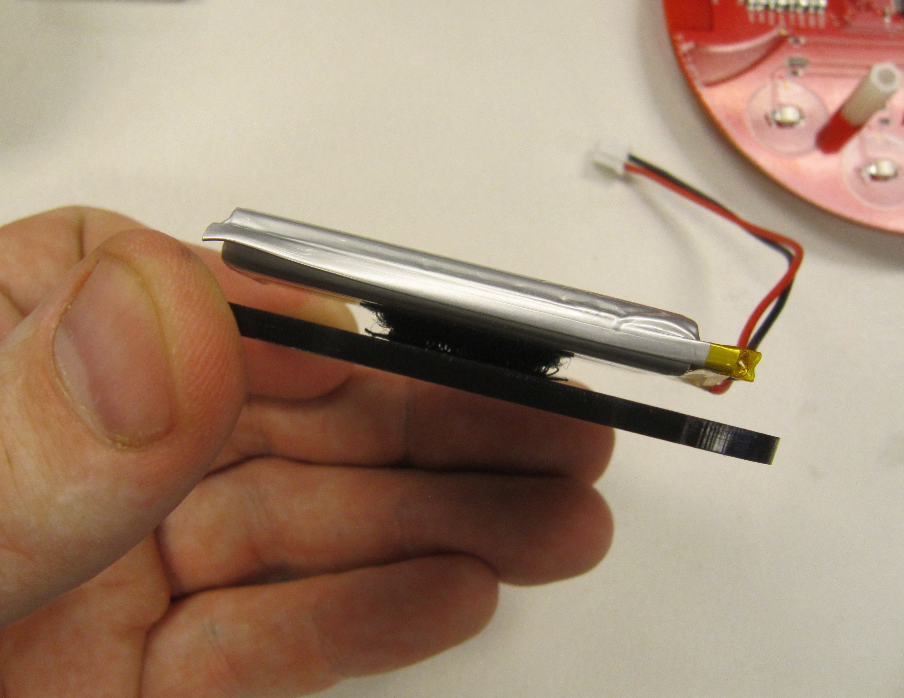
Using a 1 inch section of Velcro tape, or double sided tape. Attache the Lipo battery to the acrylic. The battery lead should be pointing toward the left.
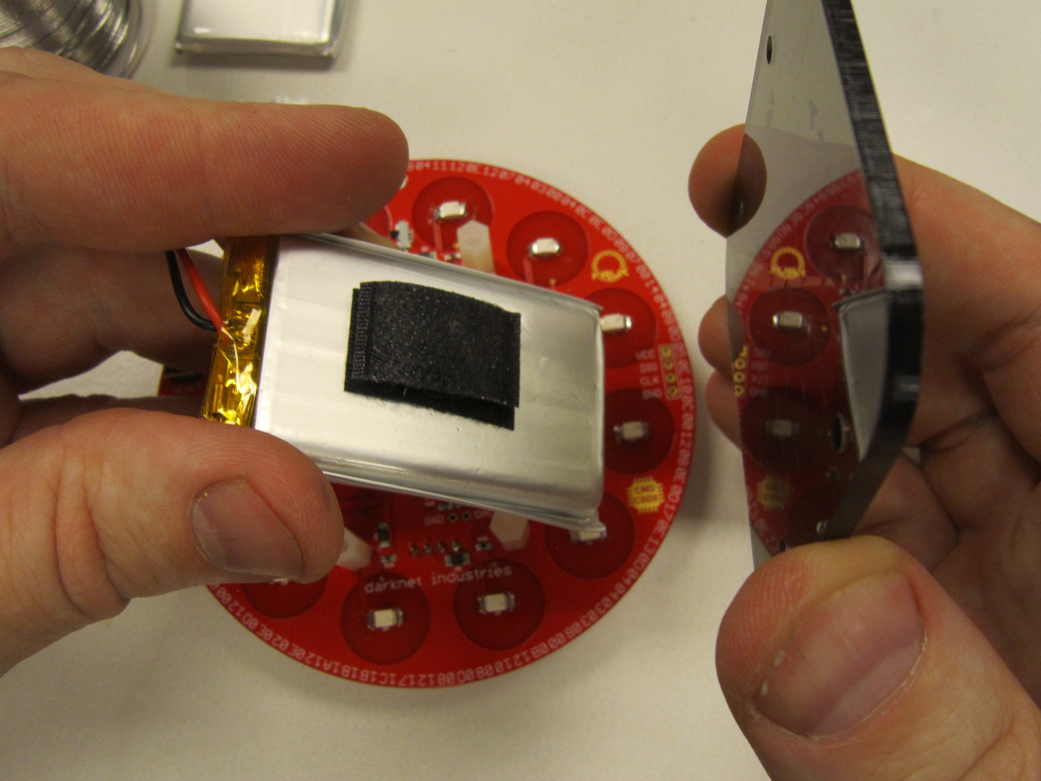
Velcro tape is preferred, as it allows for easily removing the battery from the acrylic.
The JST connector is polarized. The red wire, should be on the positive side of the connector as shown. Plug in the battery. The connector is snug, so use your other hand to hold the JST connector on the PCB when inserting the battery to avoid accidentally damaging the connector.
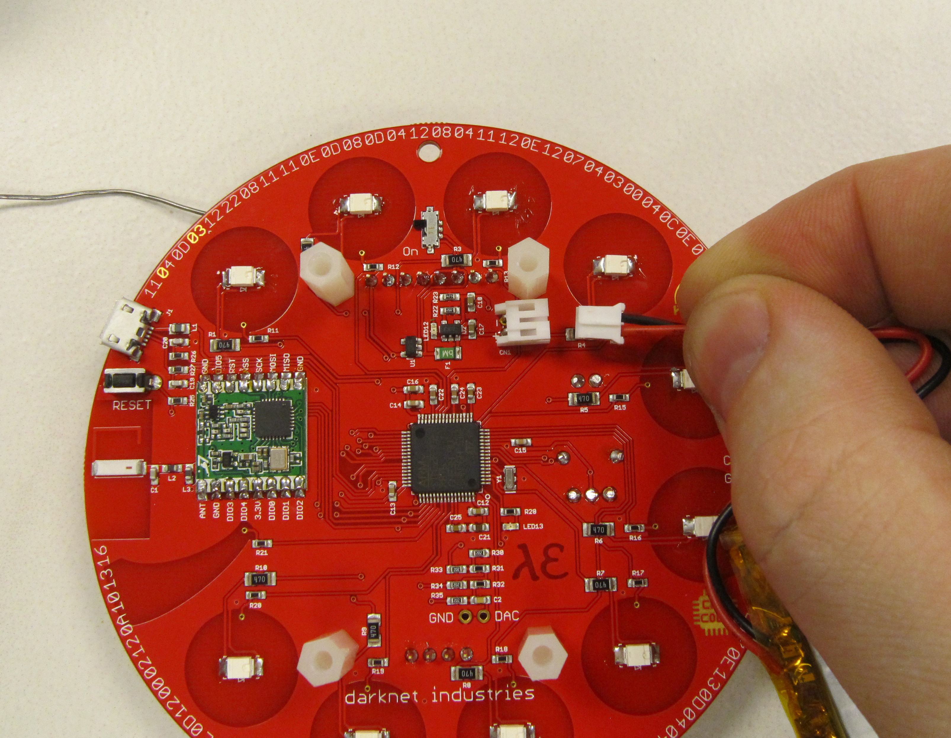
The battery lead will route as shown. This ensures that any excess wire does not get snagged by clothing, other badges, or any other number of things that are out to attack your badge.
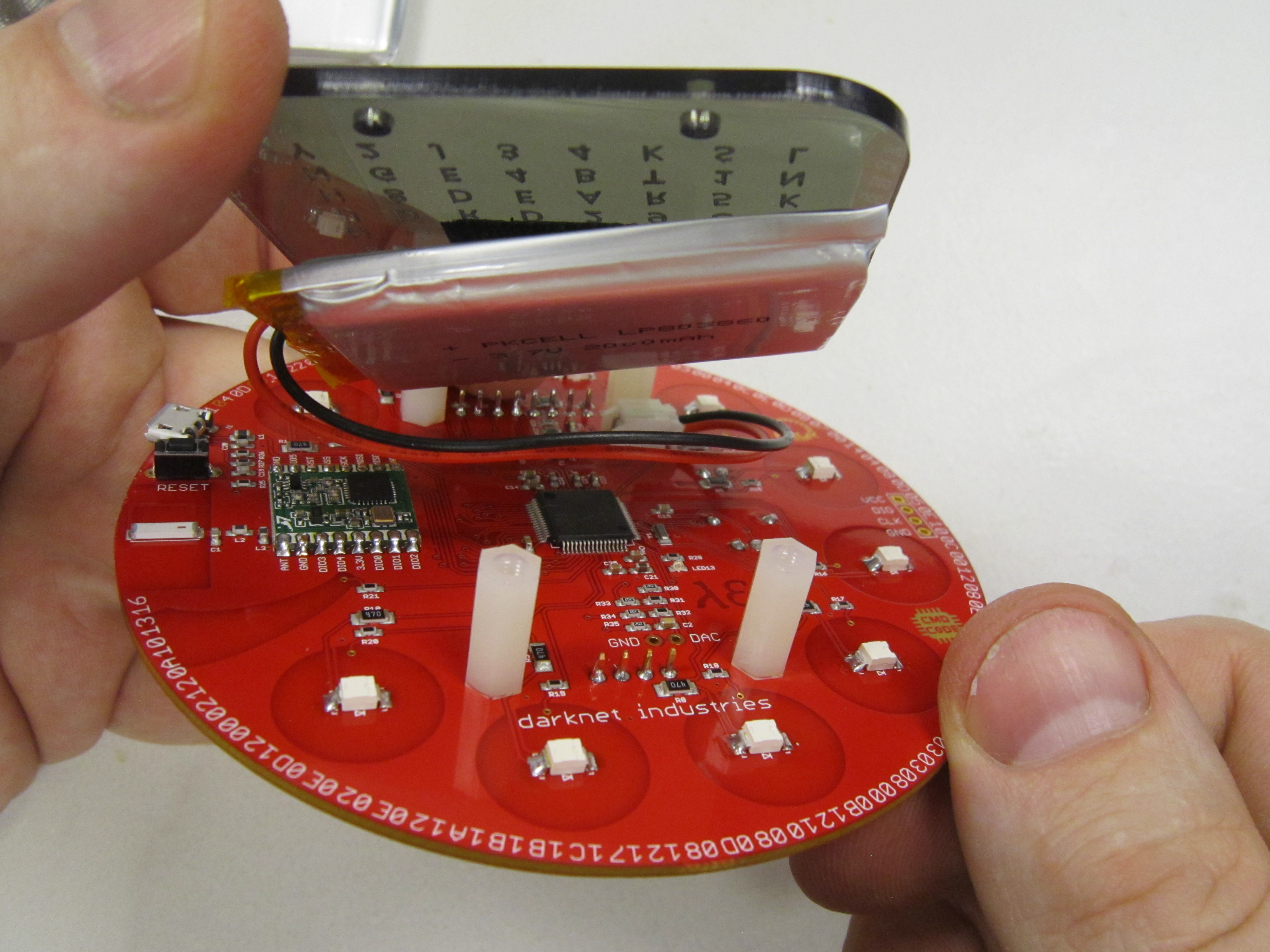
For initial power up, it is not recommended to attach the acrylic to the stand offs just yet. This allows you to quickly turn the power switch off then disconnect the battery from the JST connector in the even there is a problem.
Power on your badge.
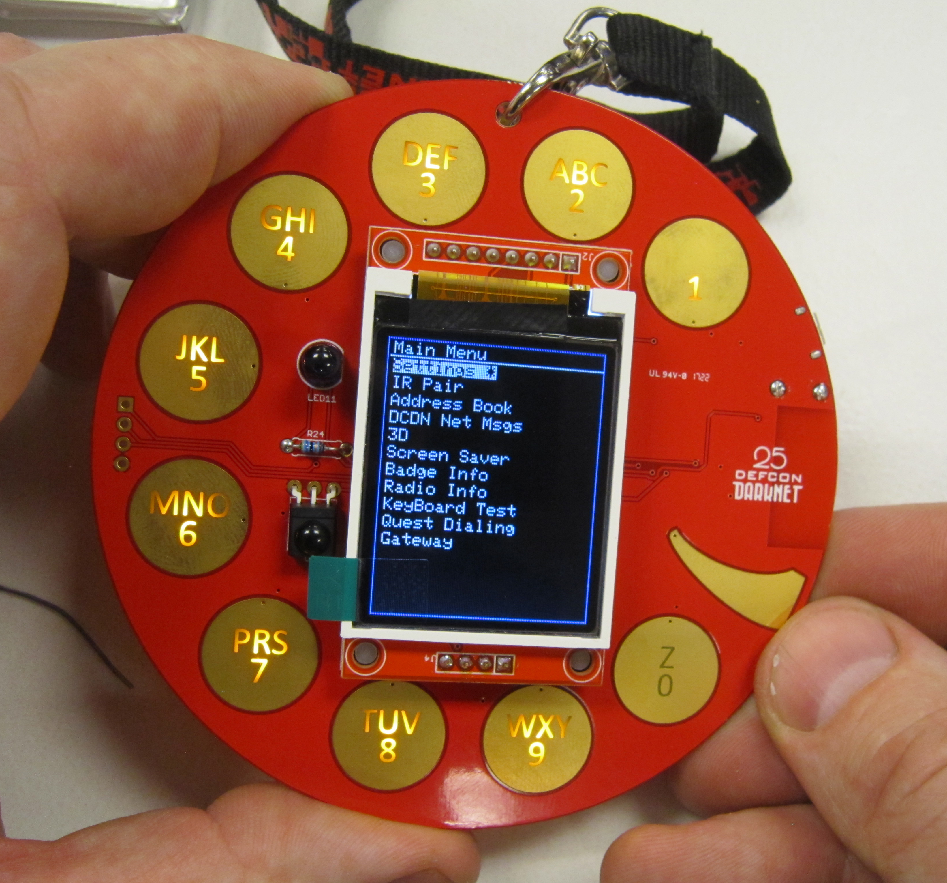
Note: If your badge has not been programmed yet, then power on init sequence may not take place. Most but not all of the badges were programmed ahead of time with alpha firmware. You will still need to get your firmware updated even if your badge has the alpha firmware.
Now find someone else who has a badge and pair your badges together. See how many of the badge's secrets you can unlock.
![]()
