
These are the assembly instructions for the DefCon DarkNet 2016 Badge Kit.
This badge not only is an excellent opportunity to learn how to solder, if you do not know already, it is also a tool that is used to communicate with other agents participating in the DefCon DarkNet contest. It can be used to pair with other agent's badges, as well as is insturmental in several of the challenges you will encounter when playing with the DarkNet.
STOP! This year the micros in the badges do not come pre-programmed. Before you begin, go to the Darknet table in contest to get the latest firmare loaded, even if you do not intend on soldering your badge during DEF CON
This badge was designed to be easy to solder, as well as extremely hackable. It is based on the ARM Cortex-M3 STM32F103 microcontroller. It can programmed using a ST-Link V2 programmer.
The badge hardware was developed by Krux, and the badge firmware was developed by Smitty, and CmdC0dez.
Avoid common mistakes, and read through this guide in it's entirety before beginning. The order of assembly
matters for some components in this kit.
You will need the following tools to assemble this kit
- Temperature controlled soldering station
- Fine solder, 0.032" diameter or smaller
- De-soldering pump / de-soldering braid
- Flush cut wire cutters
- Needle nose pliers
- Fine point tweezers
- Safety glasses
- Optional: PCB vice
- Optional: Flux for SMD use
- Optional: Denatured alcohol to clean the board after soldering
When soldering, it is important to always follow safe work habits. Be mindful of yourself and others. The following documents address some of the safety concerns when soldering
- Soldering Safety
- Lead Soldering Safety Guidelines
- Lead-Free_Solder_Fumes_Increase_Need_for_Fume_Extraction
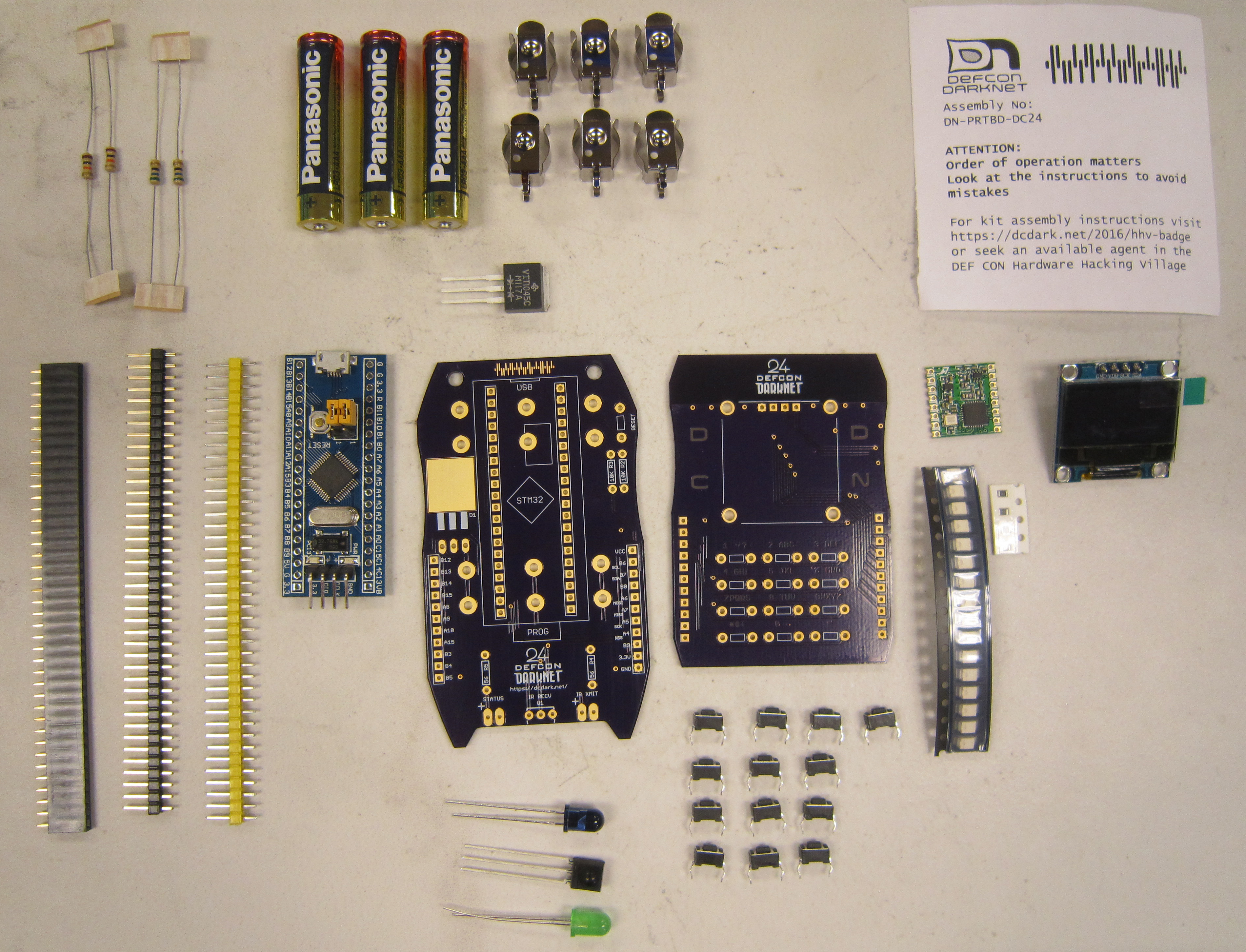
Before you get started, take a moment to ensure that all the components have been included with the kit.
Note: This is also a good time to turn on your soldering iron. For leaded solder, 320 degrees Celsius is a good working temperature.
- Two Printed Circuit Boards [in OSH Park purple]
- One STM32F103C8T6 Microcontroller with header
- One RFM69HCW-915S2 HopeRF radio module
- One OLED display module
- Three AAA batteries
- Six battery terminals
- One 5mm Green LED
- One 5mm Vishay IR LED
- One Vishay IR Receiver Module
- Two 56 Ohm 1/4W 5% carbon film resistors [Green Blue Black]
- One 10K Ohm 1/4W 5% carbon film resistor [Brown Black Orange]
- One VIT1045C-M3/4W Dual Schottky Diode TO-262AA
- Thirteen Tactile Switches SPDT
- Four SMD 0805 47 Ohm thin film resistors
- Sixteen SMD OSRAM Yellow LEDs
- One 40 position male header
- One 40 position female header
- One DefCon DarkNet Lanyard
Click on any of the images for a high-resolution version.
As stated, the micro controllers that come with these kits have not been programmed yet. Visit the darknet table, to test and get the latest firmware put on your micro controller.
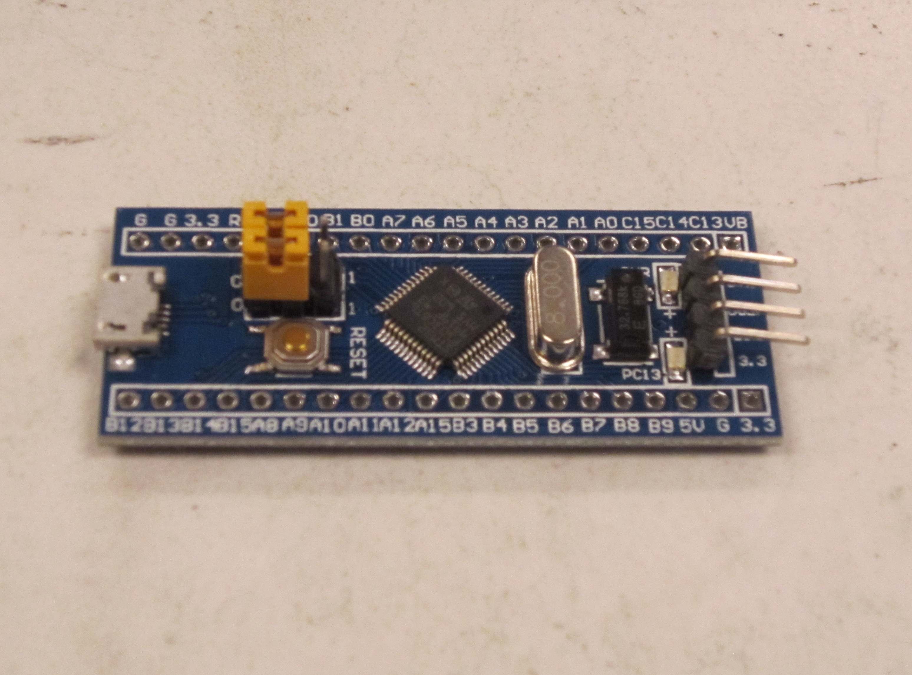
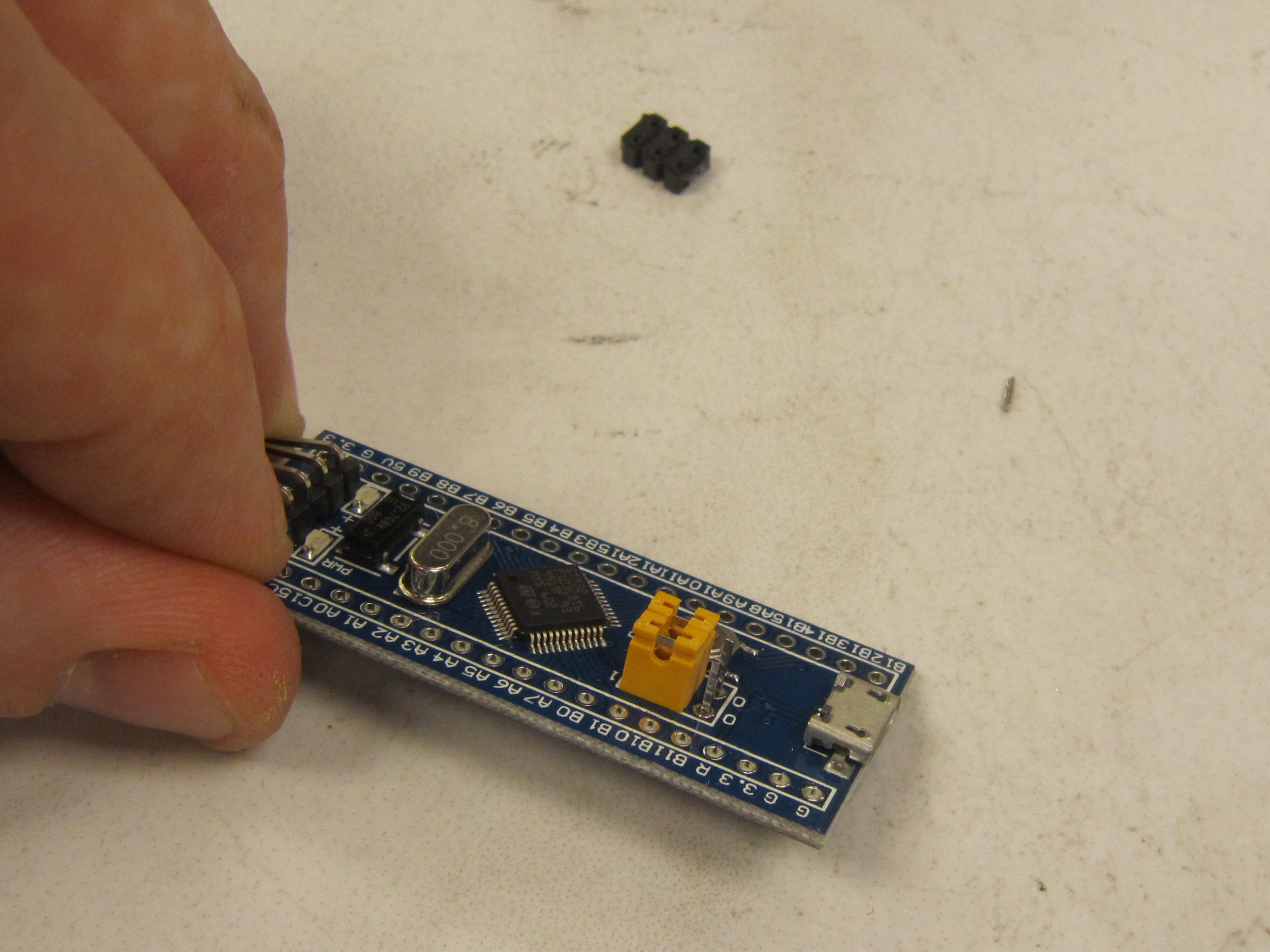
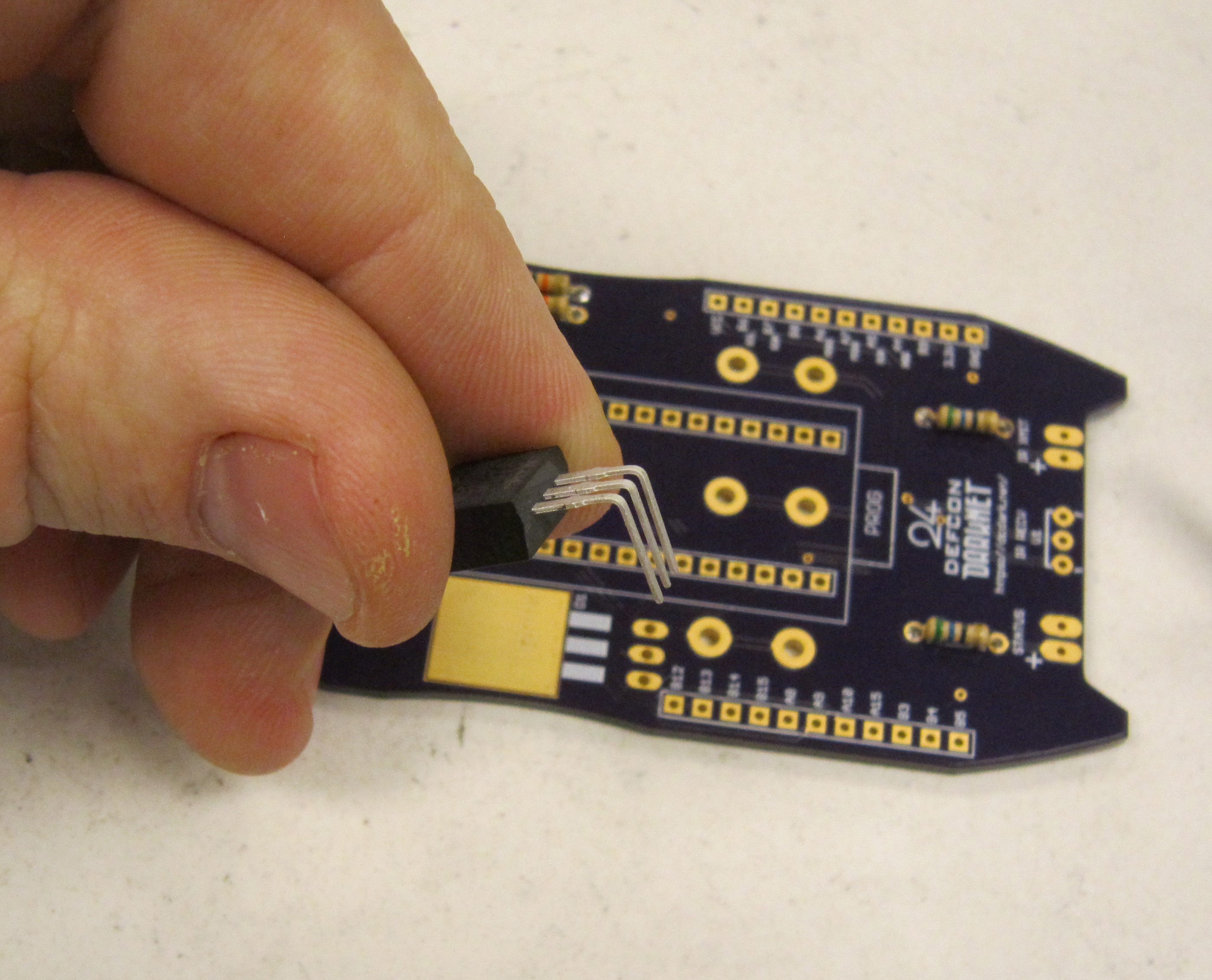
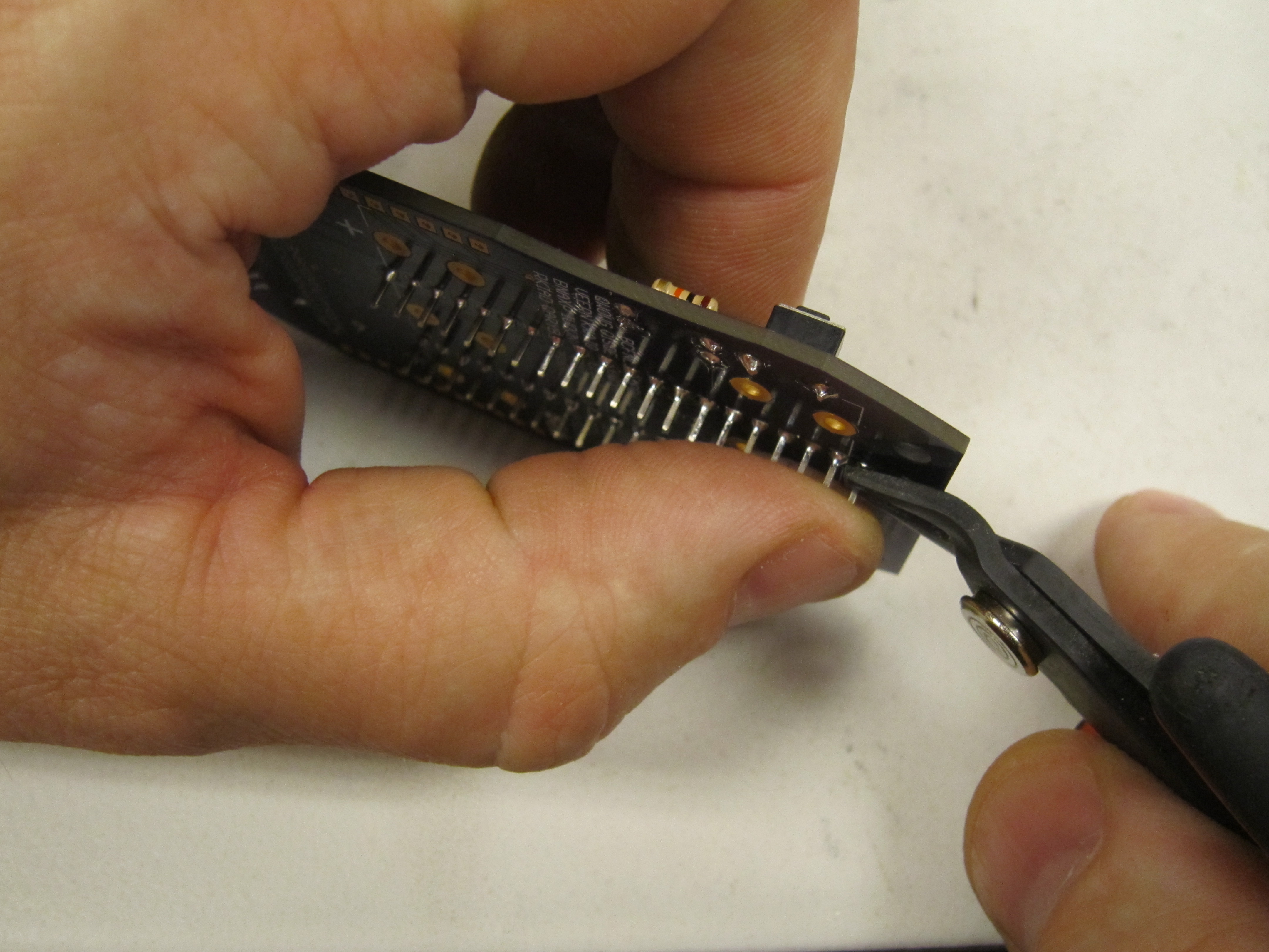
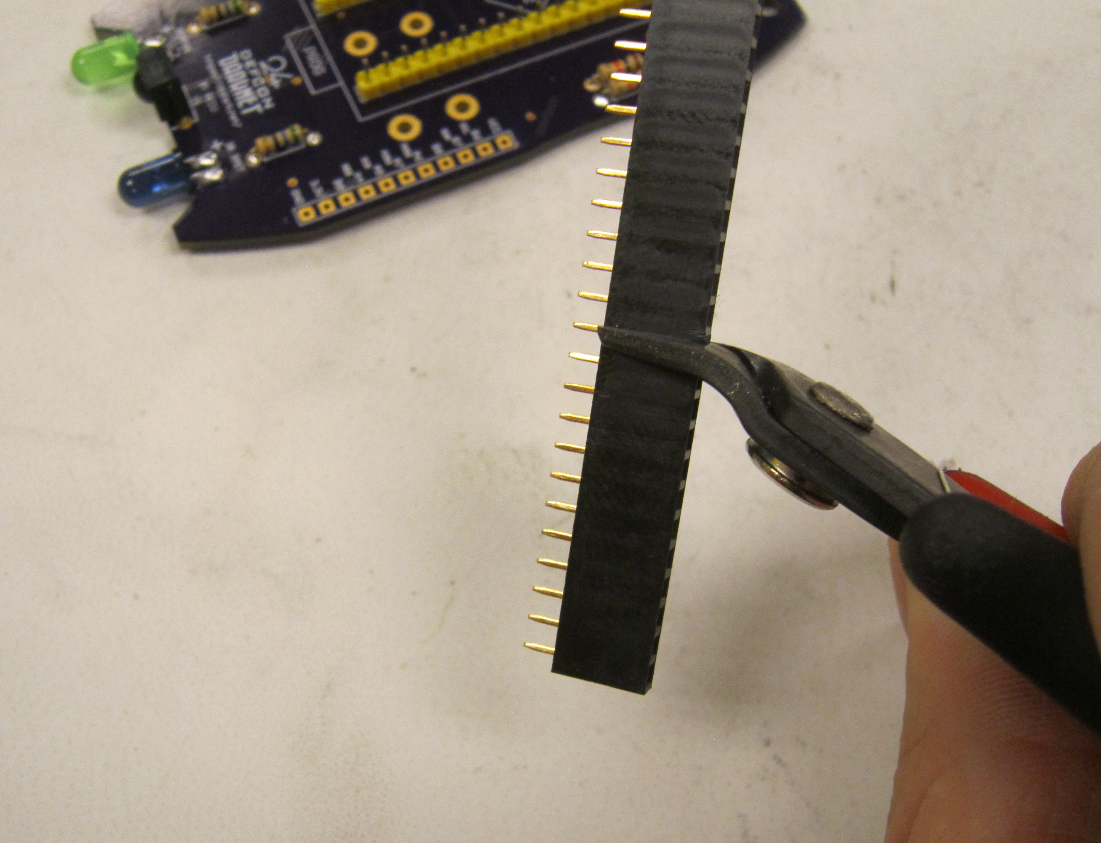
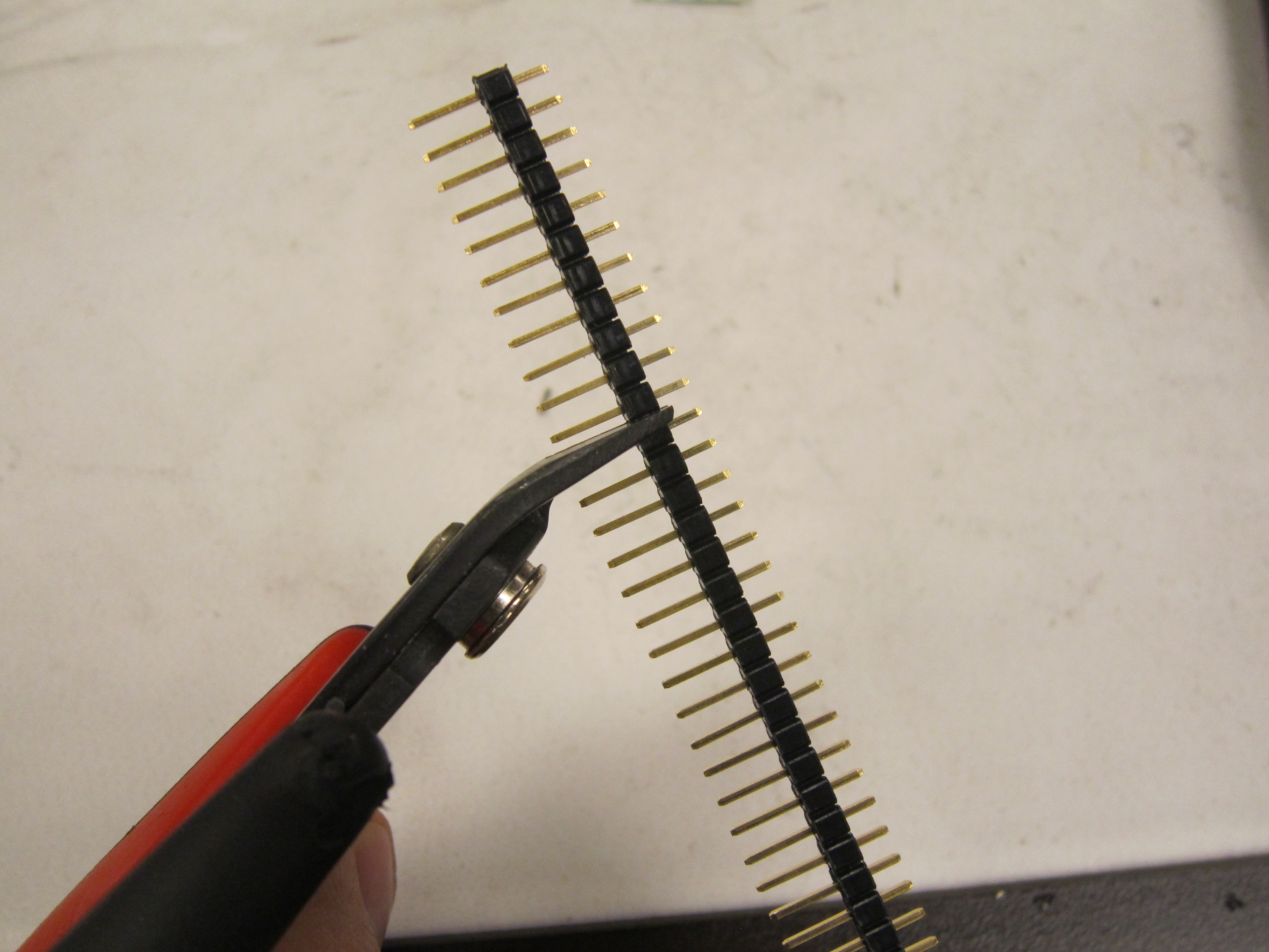
In order to fit the micro board between the we have to modify the programming select headers. We do this by carefully removing the black spacer at the bottom of the headers
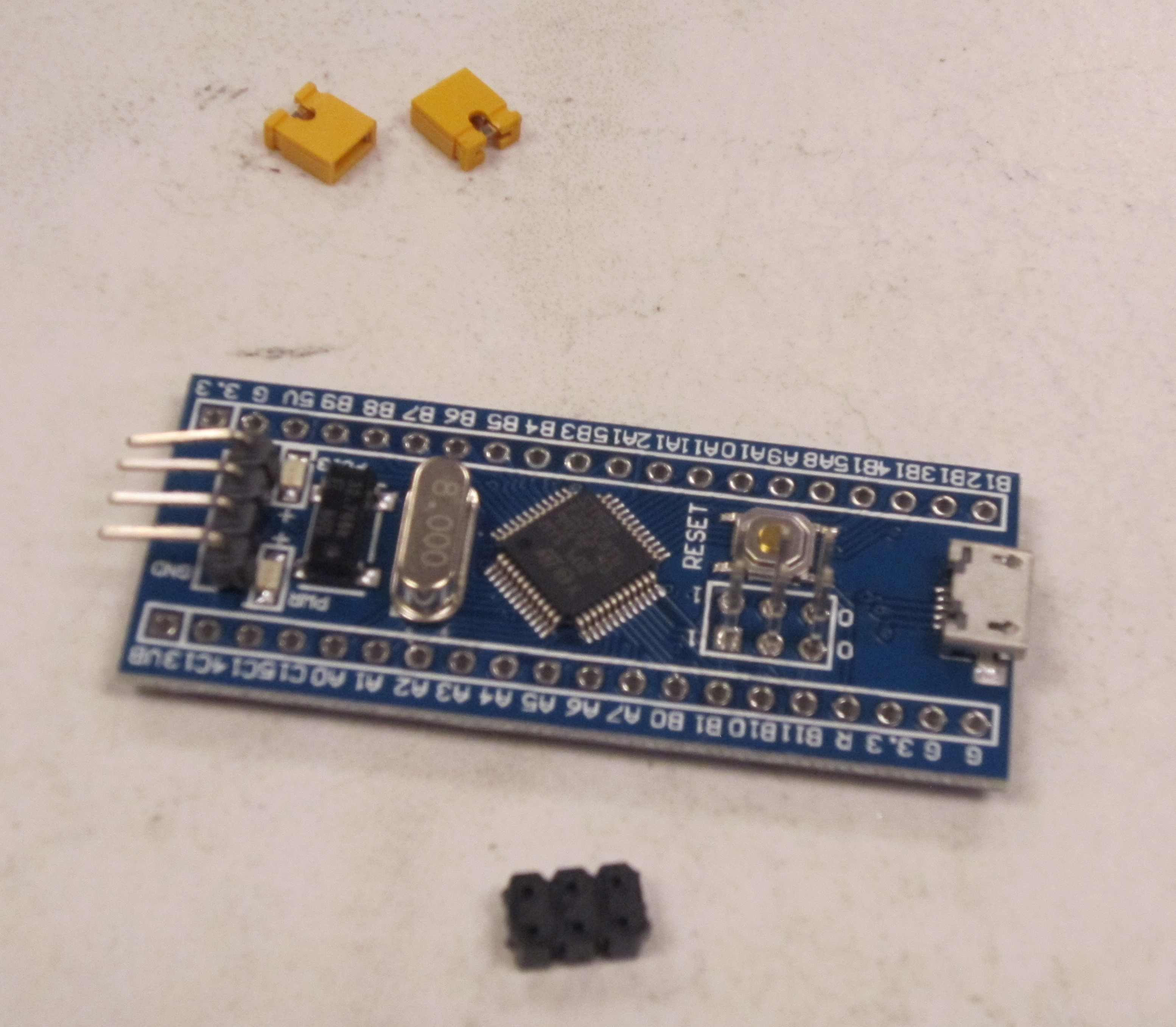
Next trim the headers so they are just shorter than the jumpers.
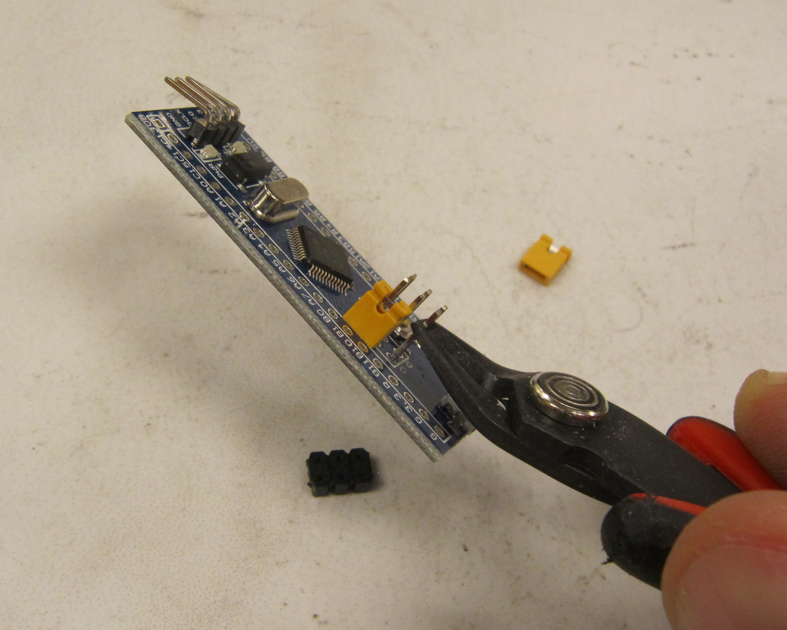
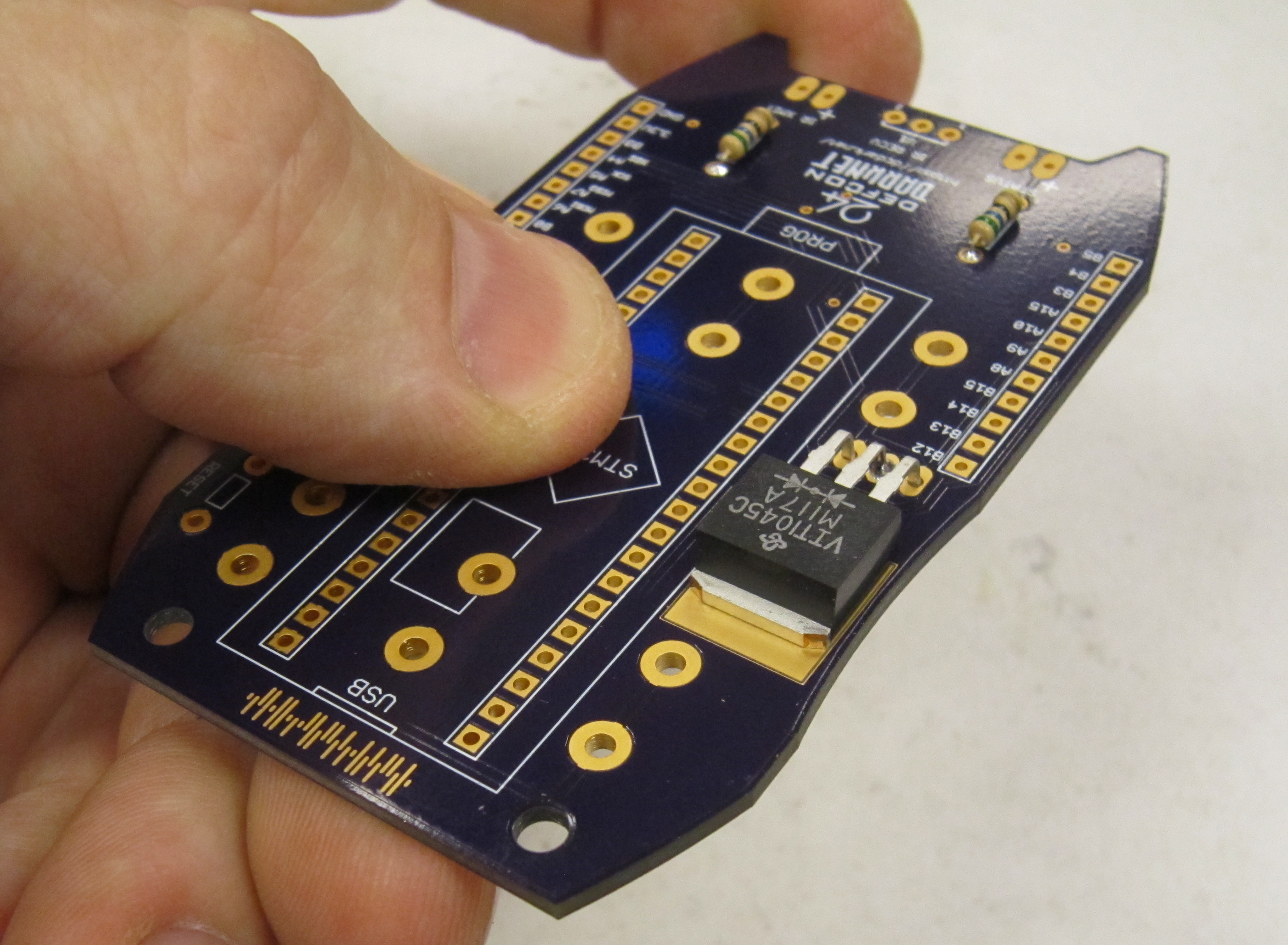
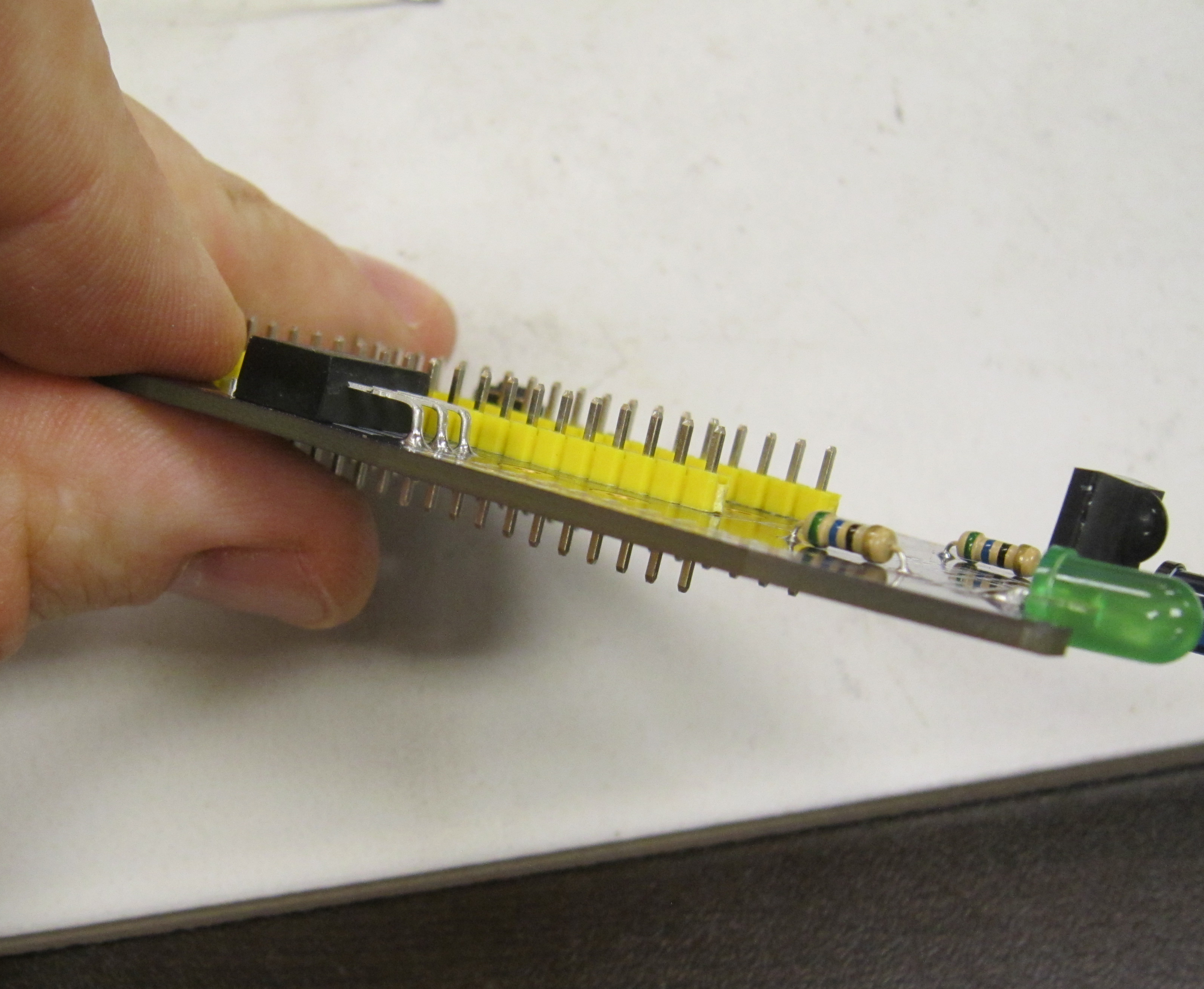
Your final micro should look like this:
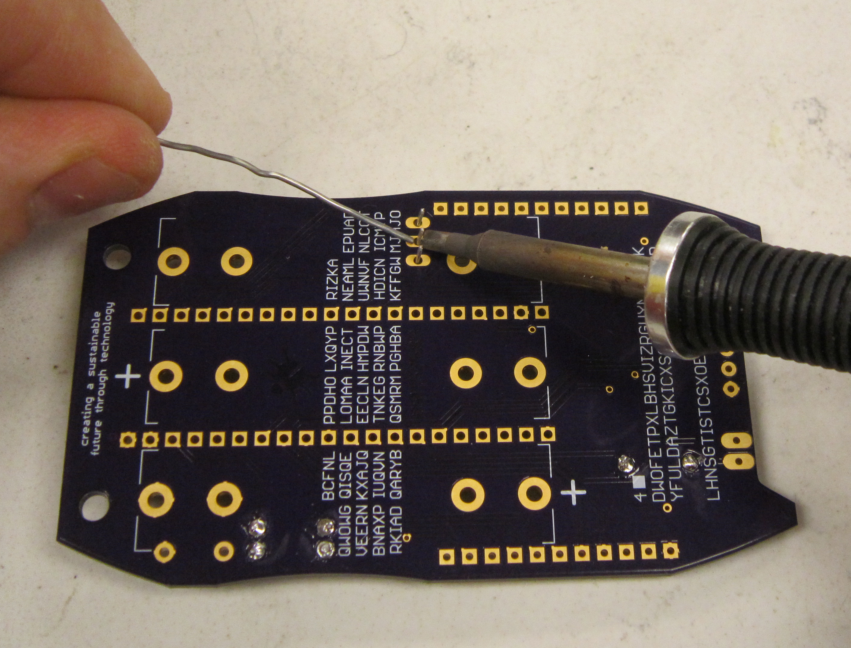
Utilizing a PCB vice as shown is useful, but not required for the assembly of this kit. Common practice when a PCB holder is not available is to add the components from smallest component to largest. This lets you utilize the weight of the PCB in order to keep components in place when soldering. This guide makes use of this technique.
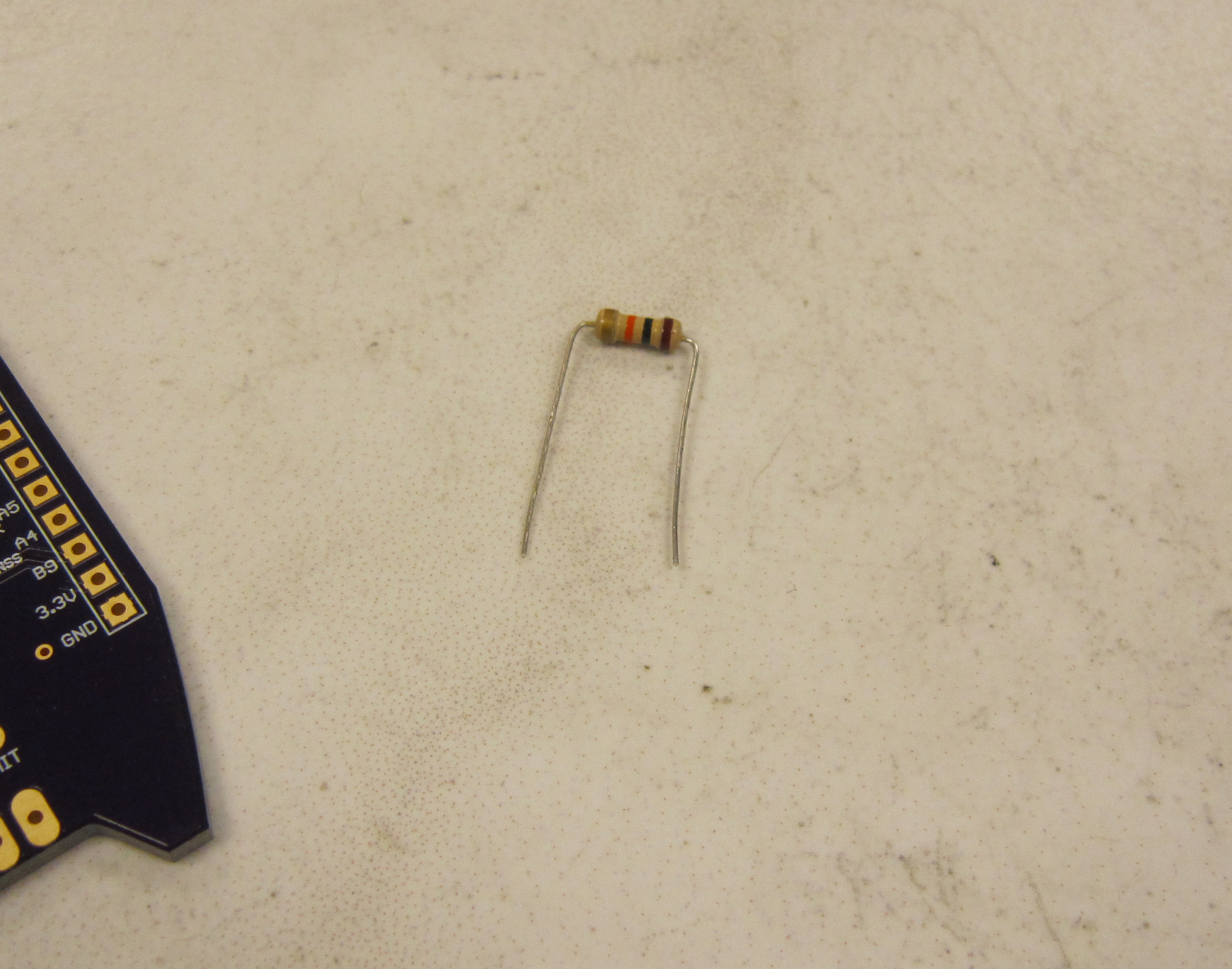
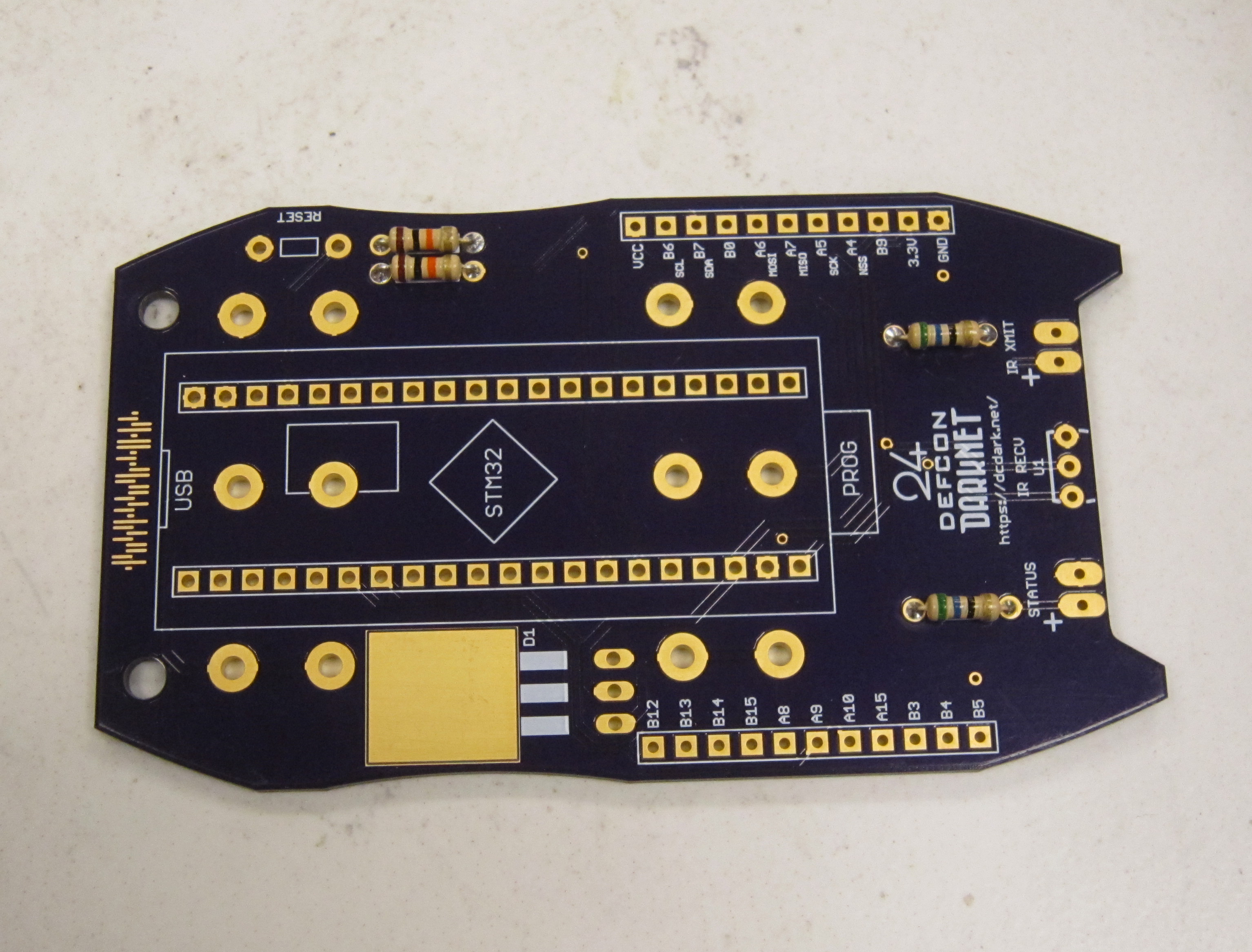
Start by soldering the 10 KOhm resistors R2, and R3. They can be identified by their orange black brown resistor color code. Resistors do not have a polarity and can be installed in either direction.
The following resistor color code chart is useful in identifying resistors values.

Start by bending the leads as shown, so they may be inserted into PCB.
Populate the components, so they are on the top side of the board. Each component is marked with it's part designator. The resistors also include their required value. The parts should lay flush with the PCB.
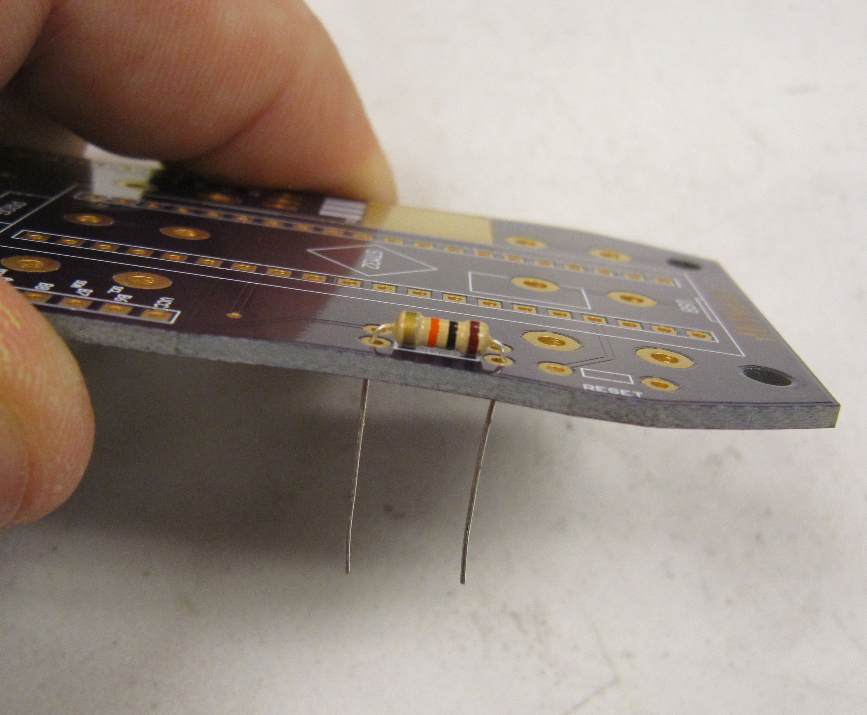
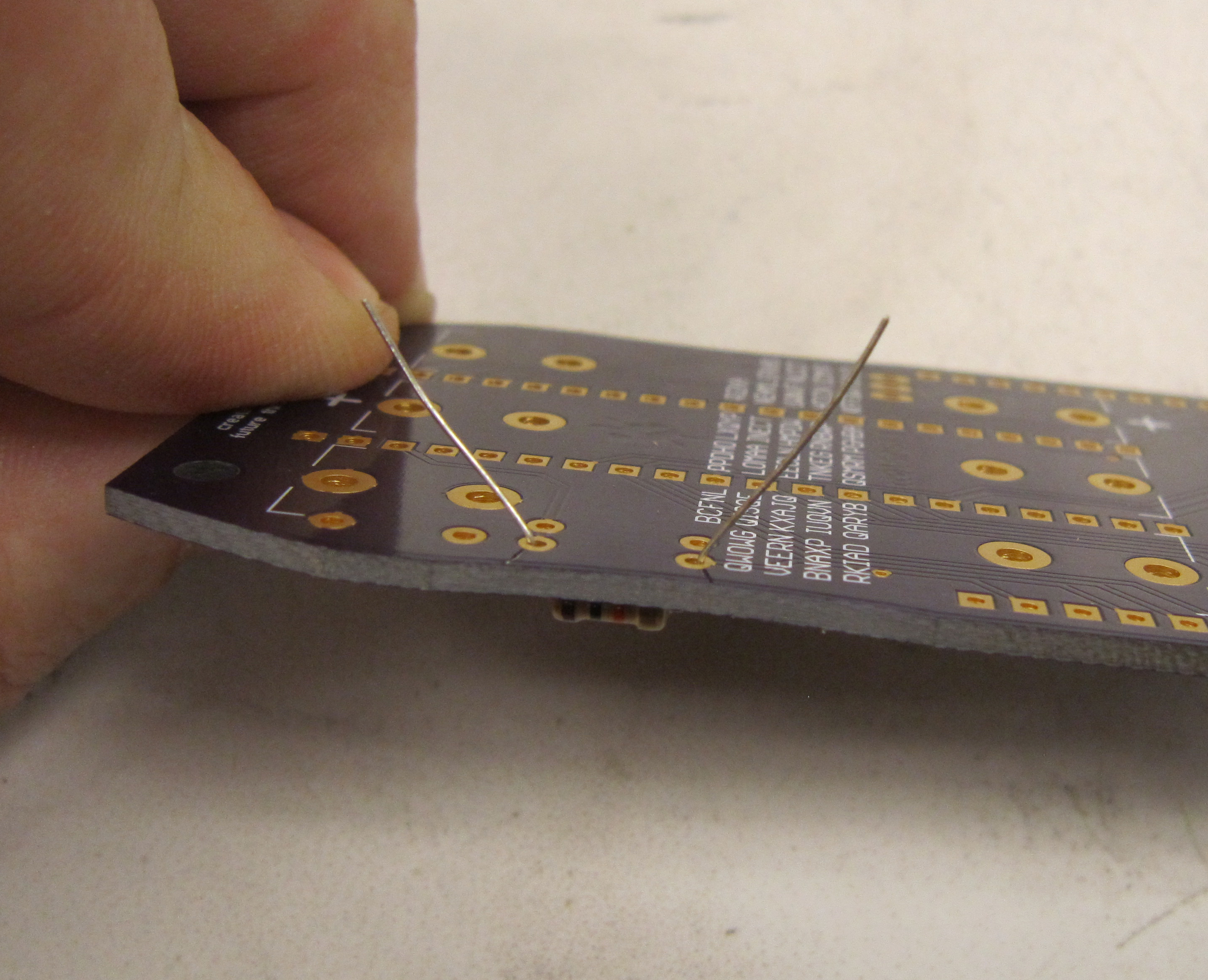
To aid in soldering, and to help keep the components in place, the leads may be splayed at a slight angle to hold the parts in place. Double check that the parts are still flush with the PCB before soldering.
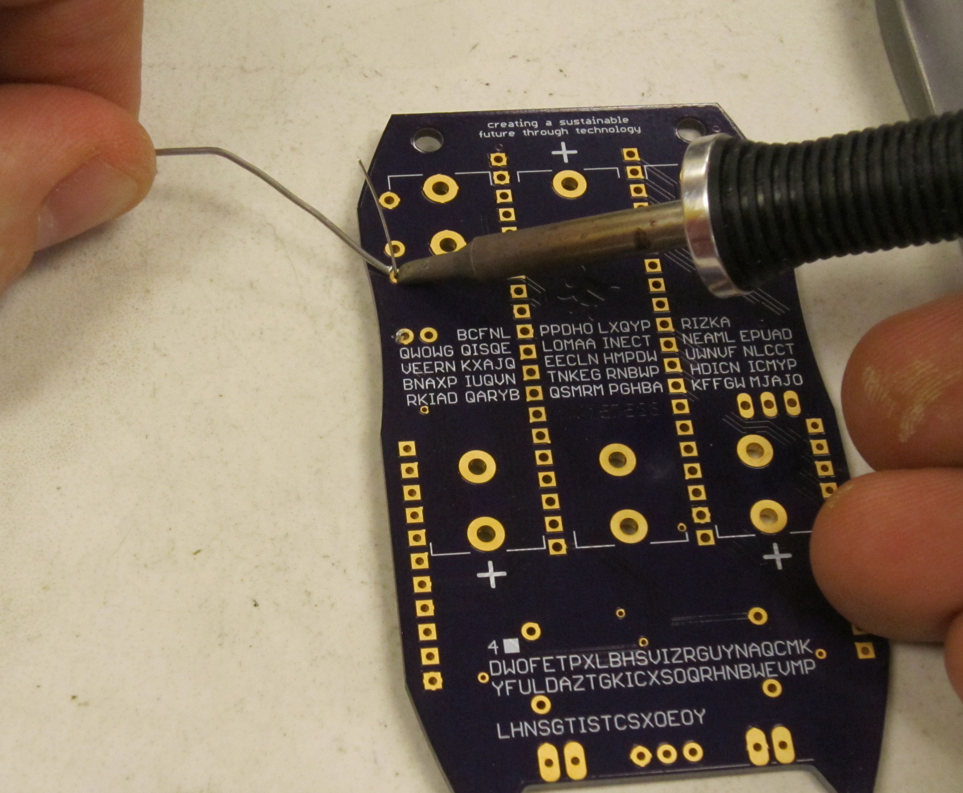
Ensure the tip of your soldering iron is always kept clean. It should be shiny in appearance. Removing the oxidation by wiping the soldering iron on a solder sponge.
When using a chisel tip as show, the flat of the tip can be used. When using a conical tip, use the section of the iron just to the side of the tip. This gives you a larger area of thermal contact and will make soldering easier.
Begin soldering by positioning the tip of the iron so that it makes firm contact with both the solder pad on the PCB and the lead of the component. This ensures that both the pad and the part both get sufficiently hot so that they are able to melt the solder and make a good electrical connection. Feed solder in sparingly on the side opposite the soldering iron. The solder should flow on the solder pad and lead of the component, forming a conical shape.
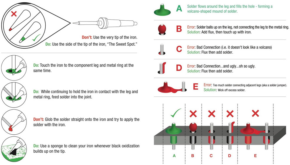
The following diagram shows more details on soldering DOs and DON'Ts
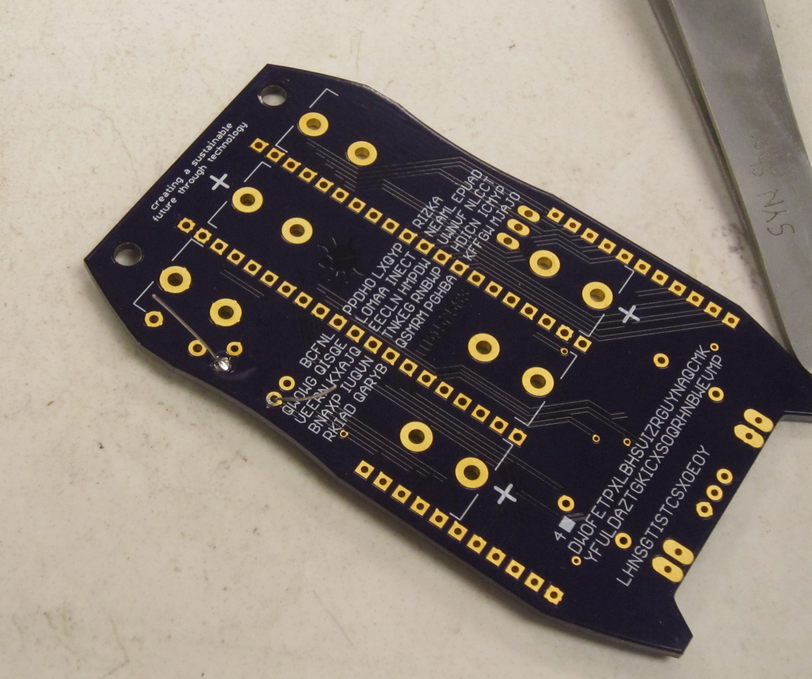
Next trim the resistor leads close to the board. This should be where the component lead meets the solder, as shown here.
Safety Tip: When cutting component leads, ensure that you are holding the lead when you cut the part to prevent the lead from becoming a projectile. Not doing this can lead to eye injury for yourself or others. You can easily do this by holding a finger tip over the lead as you cut it.
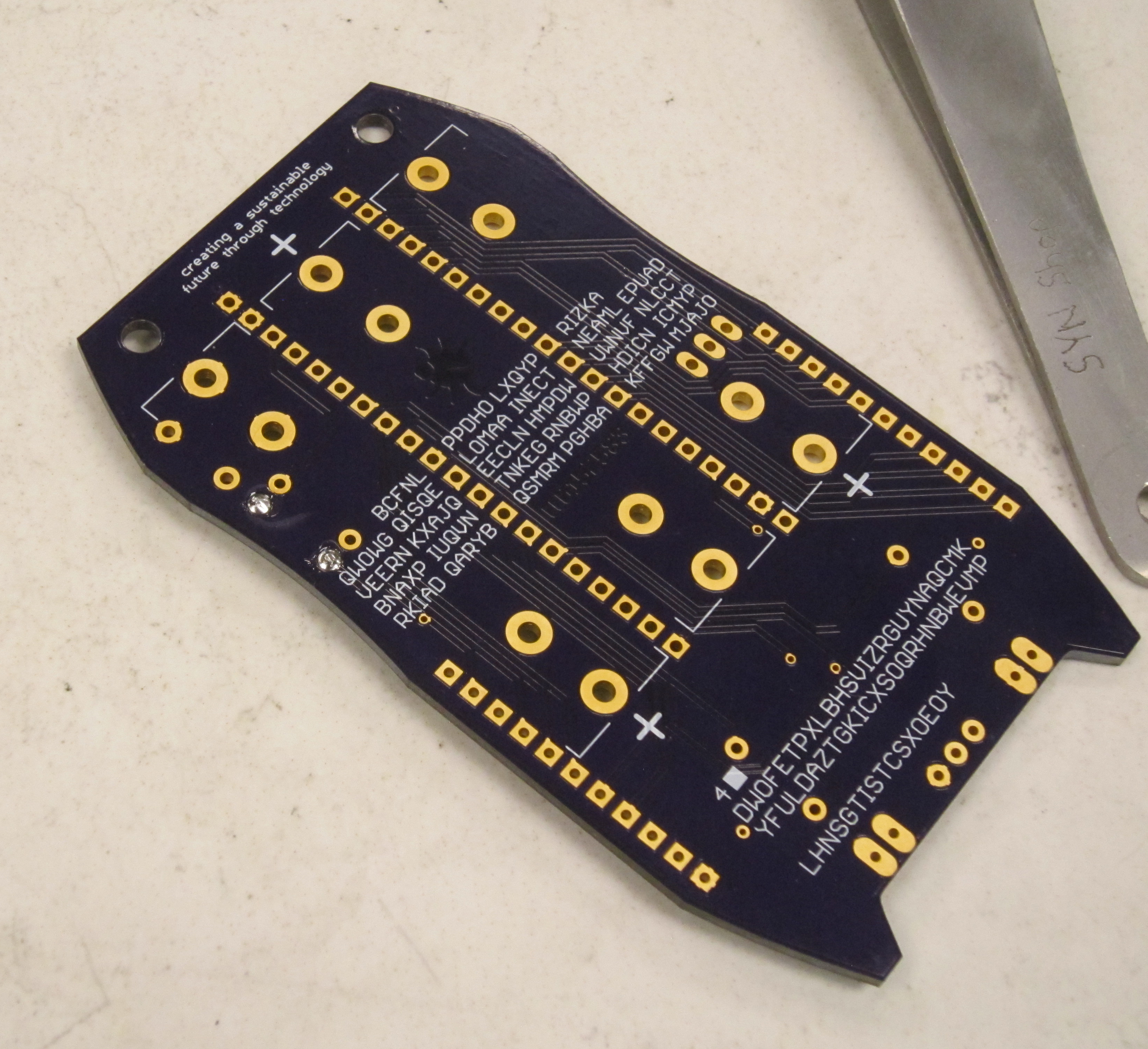
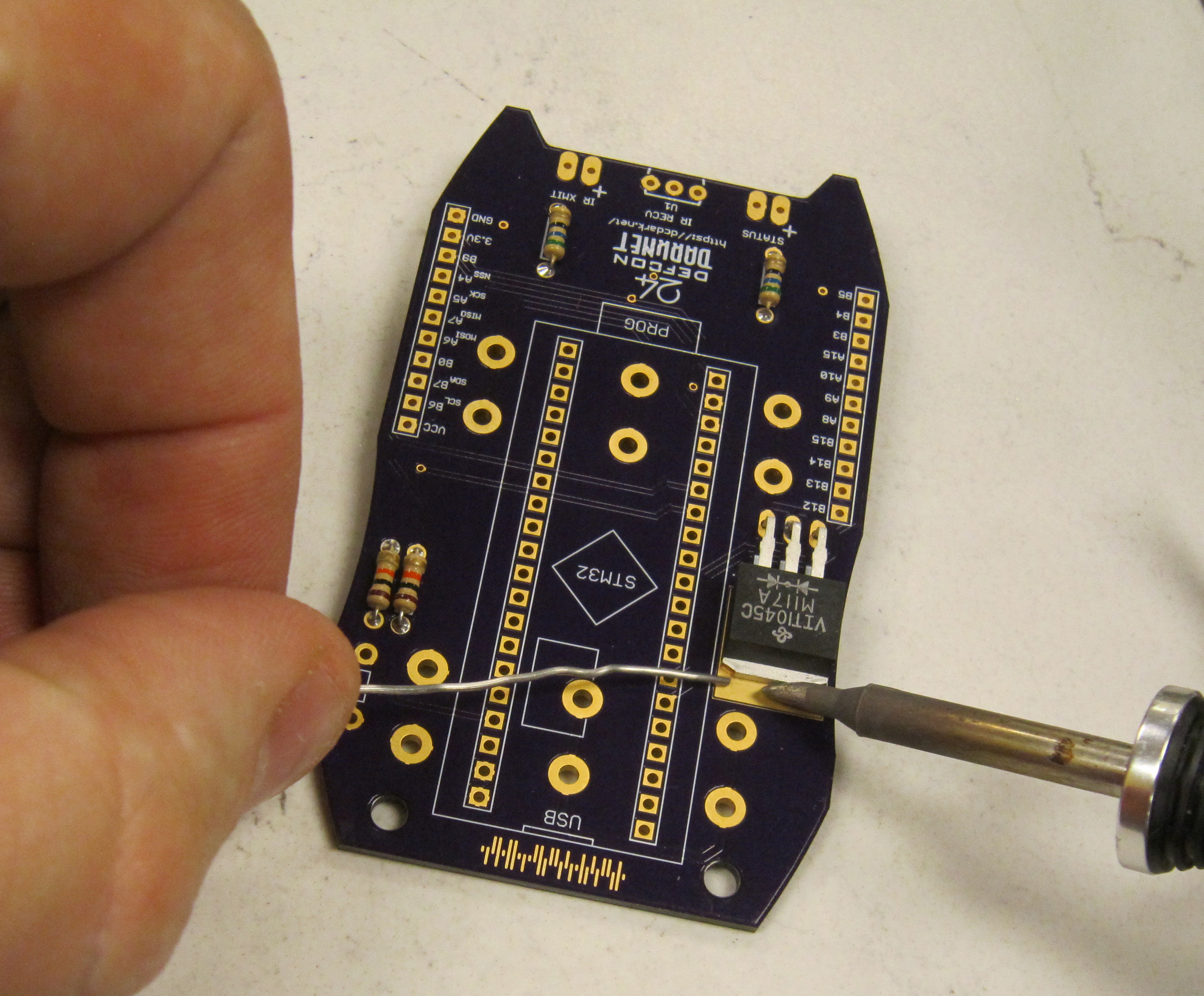
Next solder in the two 56 Ohm resistors R4 and R5. The resistor color code is green blue black.
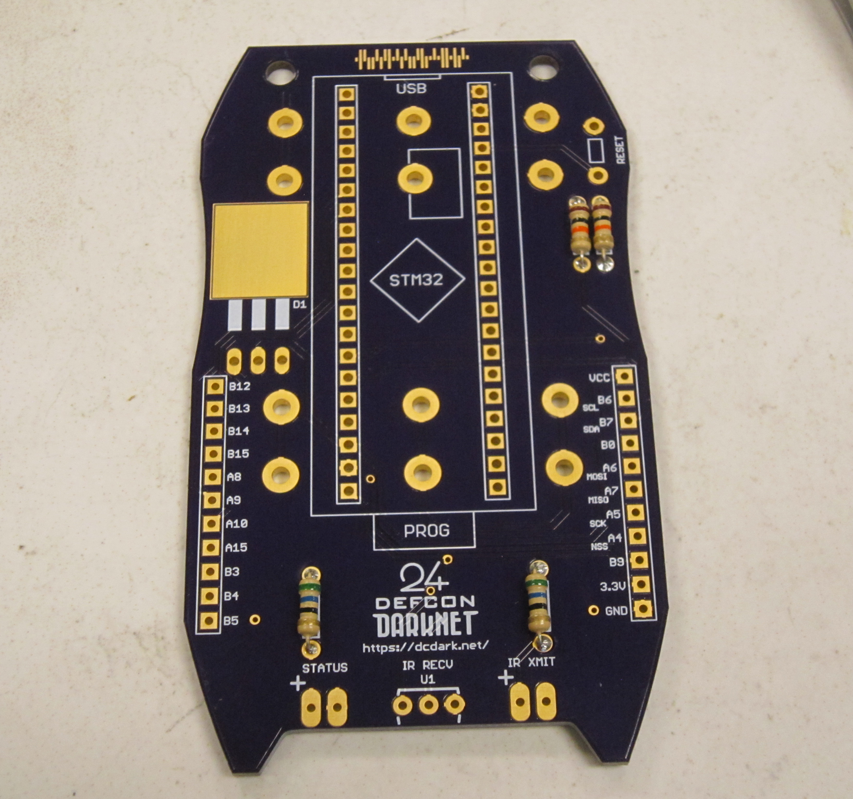
In order to allow this kit to be connected to your computer, while also being battery powered, a diode bridge is used. This ensures that voltage from the computer does not feed into the batteries. And also protects the circuit if the batteries are inadvertently installed backwards.
CAUTION: There is a flaw with the solder mask layer around this pad, which exposes the ground plane in a thin line around the pad for the protection diode. If mis-soldered this bridges power and ground. Use care to center the part, and use very little solder to connect this part to the rectangular pad.
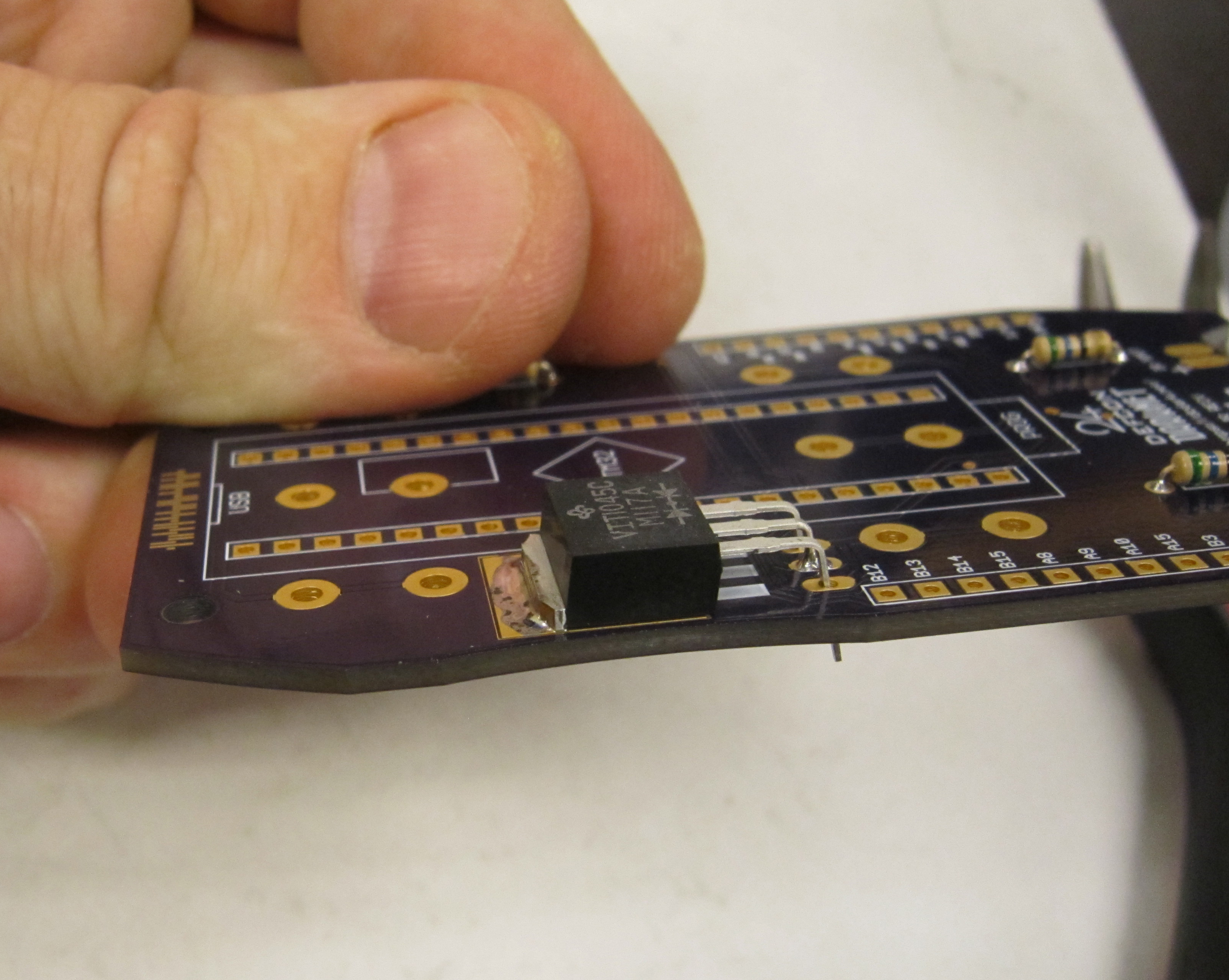
This package is installed so it lays flat to the PCB. The leads on this part will be bent at a 90 degree angle so that there is enough lead to mount the heat sink of the part on the square solder pad. The leaded edge of the part should align with the edge of the pad.
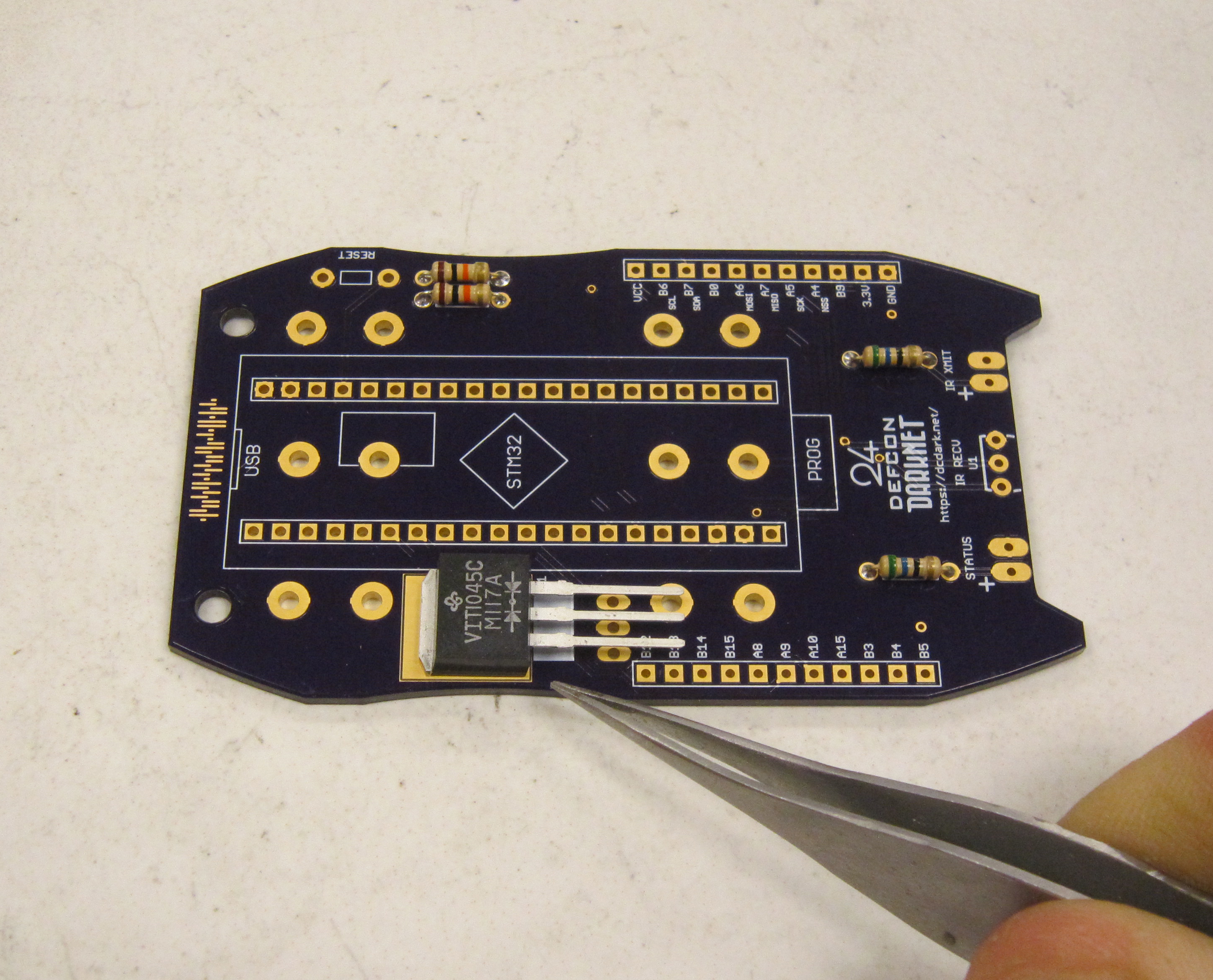
Using needle nose pliers, grasp the leads where the are above the three solder pads for the component. There should be about 7.5mm of lead between the pliers and the component.
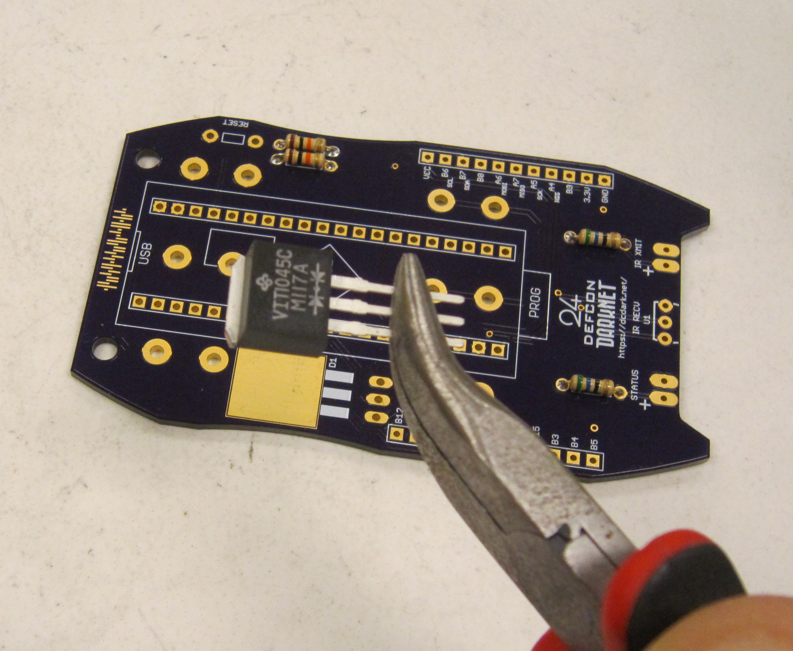
Bend the leads over as shown.
Next install the part onto the PCB. If done correctly there should be enough pad showing at the tab of the component so it may be soldered, and the entirety of the componet will be on the pad.
Next solder one of the leads of the diode bridge.
Check that the part is positioned on the pad correctly. As only one lead is soldered it can be shifted as needed. Ensure that it is not touching the ground plane on either side. If the diode bridge is not laying flat against the PCB, heat the soldered lead and adjust by pressing flat. Before soldering the remaining two leads, we will solder the tab of the component in place.
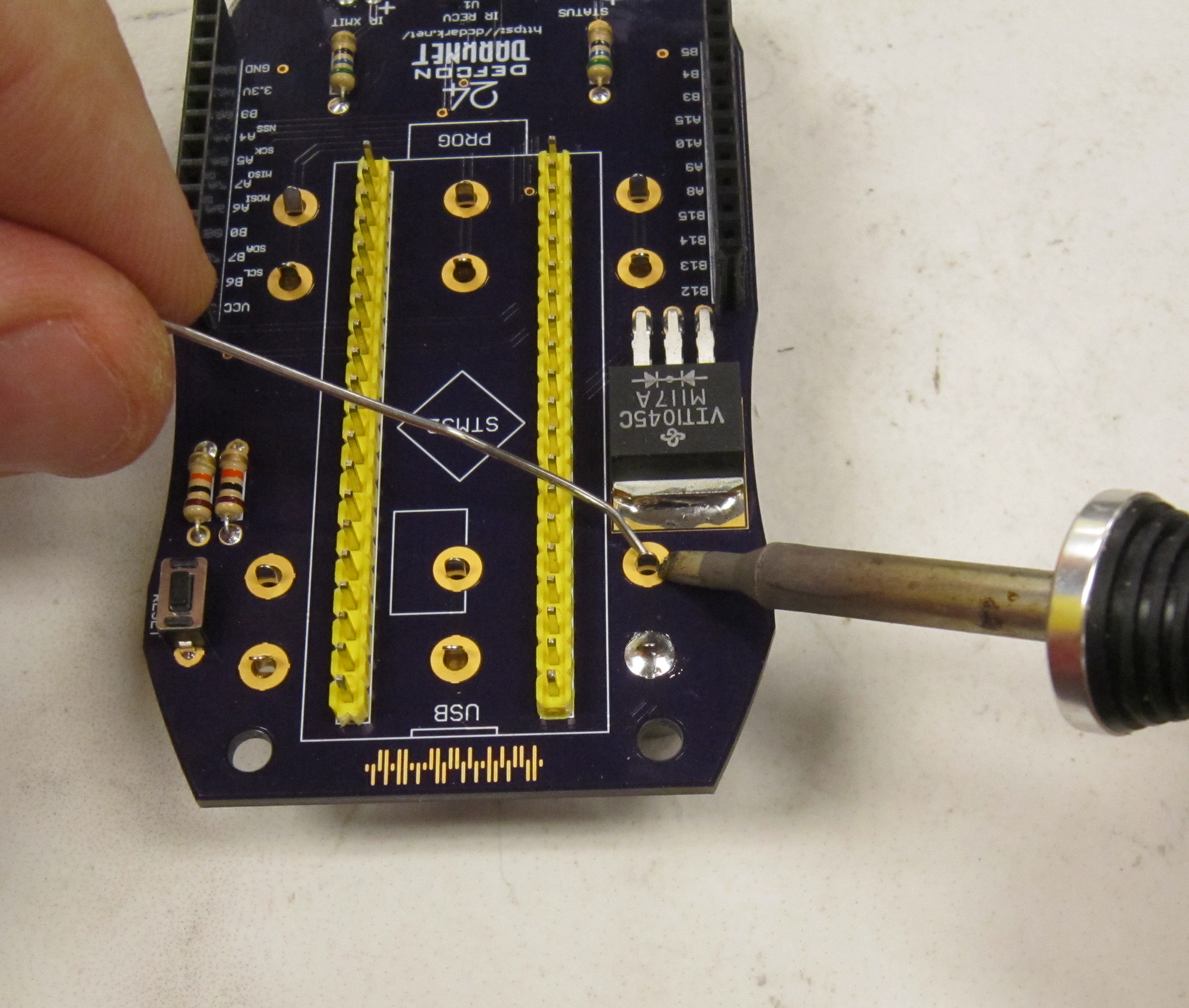
As this part has a relatively large thermal mass, it will require more time to heat up to the point where the solder will melt. Place the iron so that it is laying along both the tap of the part, and the solder pad. After a few seconds add solder, and slide the tip of the iron along the interface between the component tab and the pad.
Once sufficently hot, the solder should flow so that it covers the tab and the top of the pad.
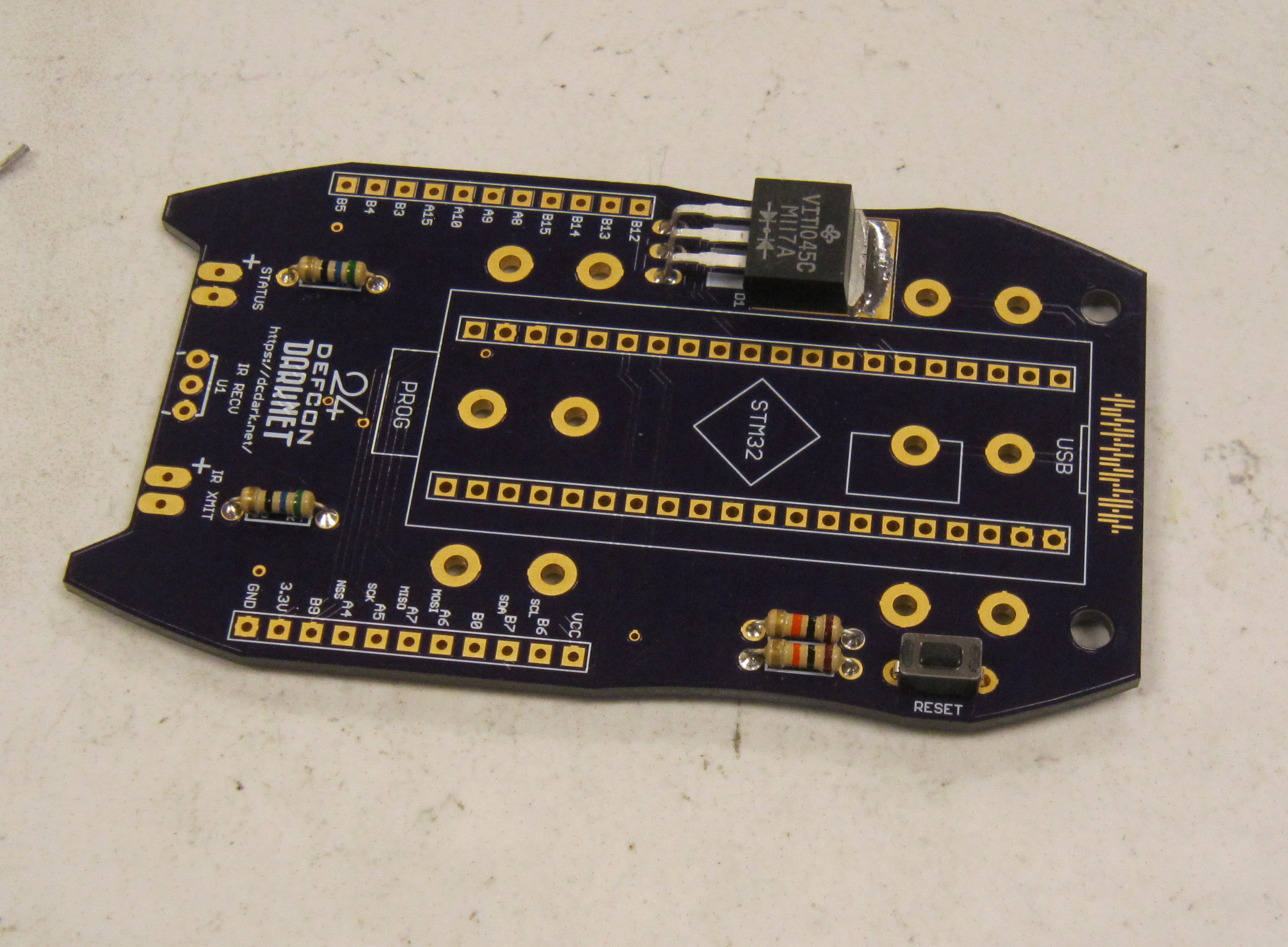
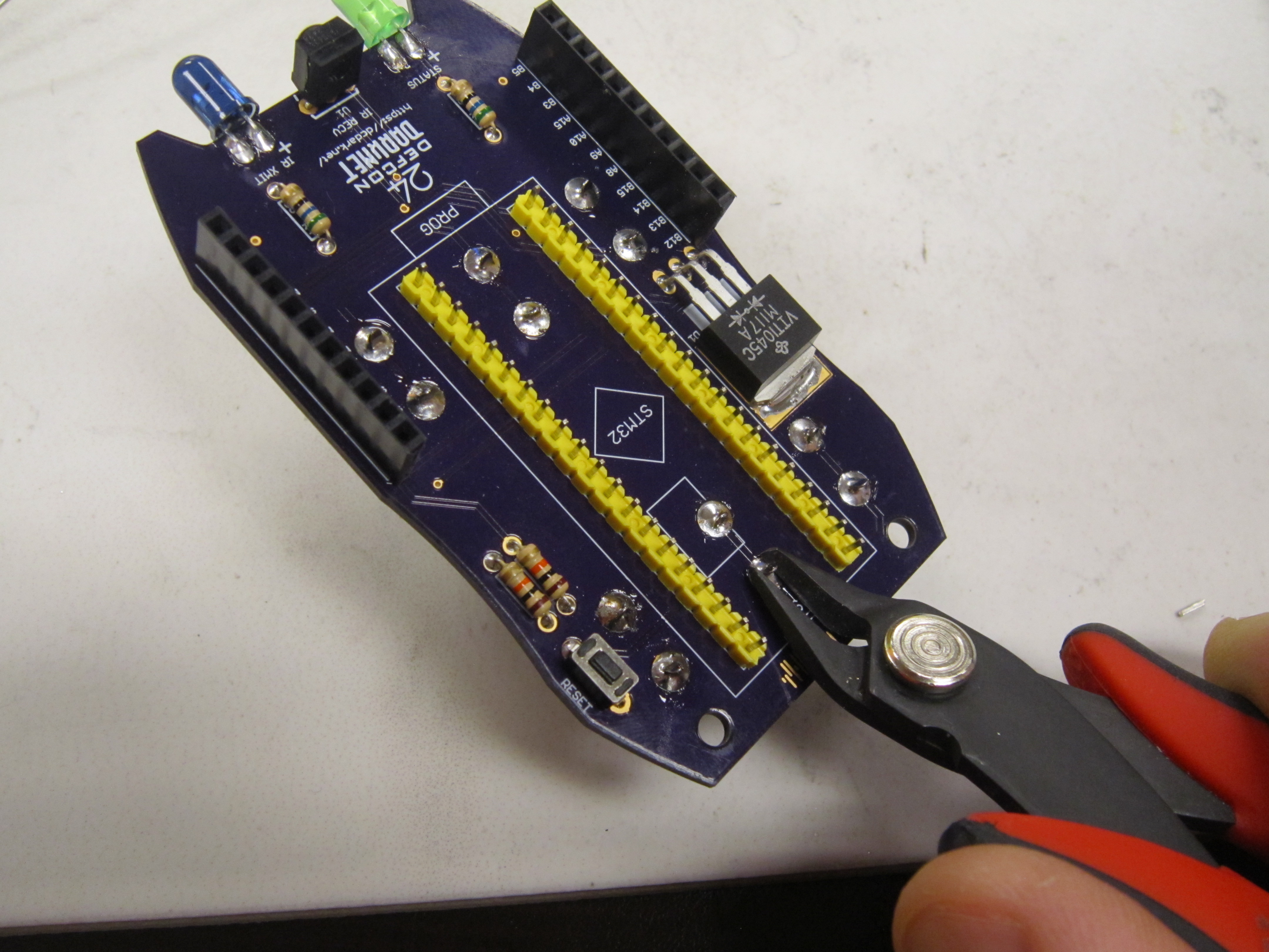
Now solder the remaining two leads, and trim flush.
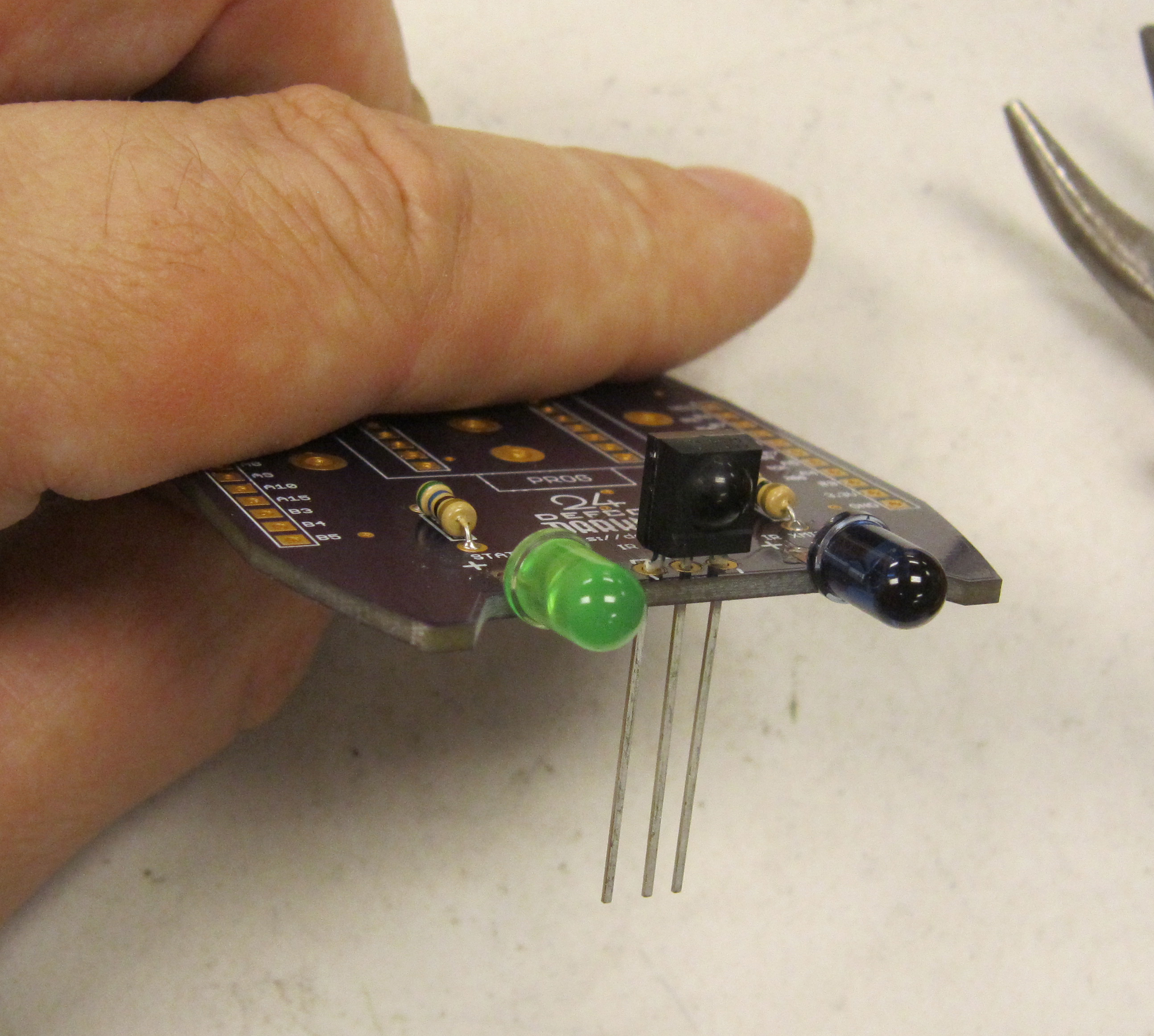
Next we will be installing the green and infrared LEDs. LEDs are polarized, and will only work if installed correctly.
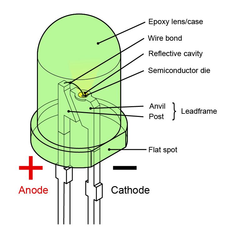
The polarity of LEDs can be determined using two methods. The leads of the LED are differing lengths, with the longer of the two leads indicating the Anode, or positive lead.
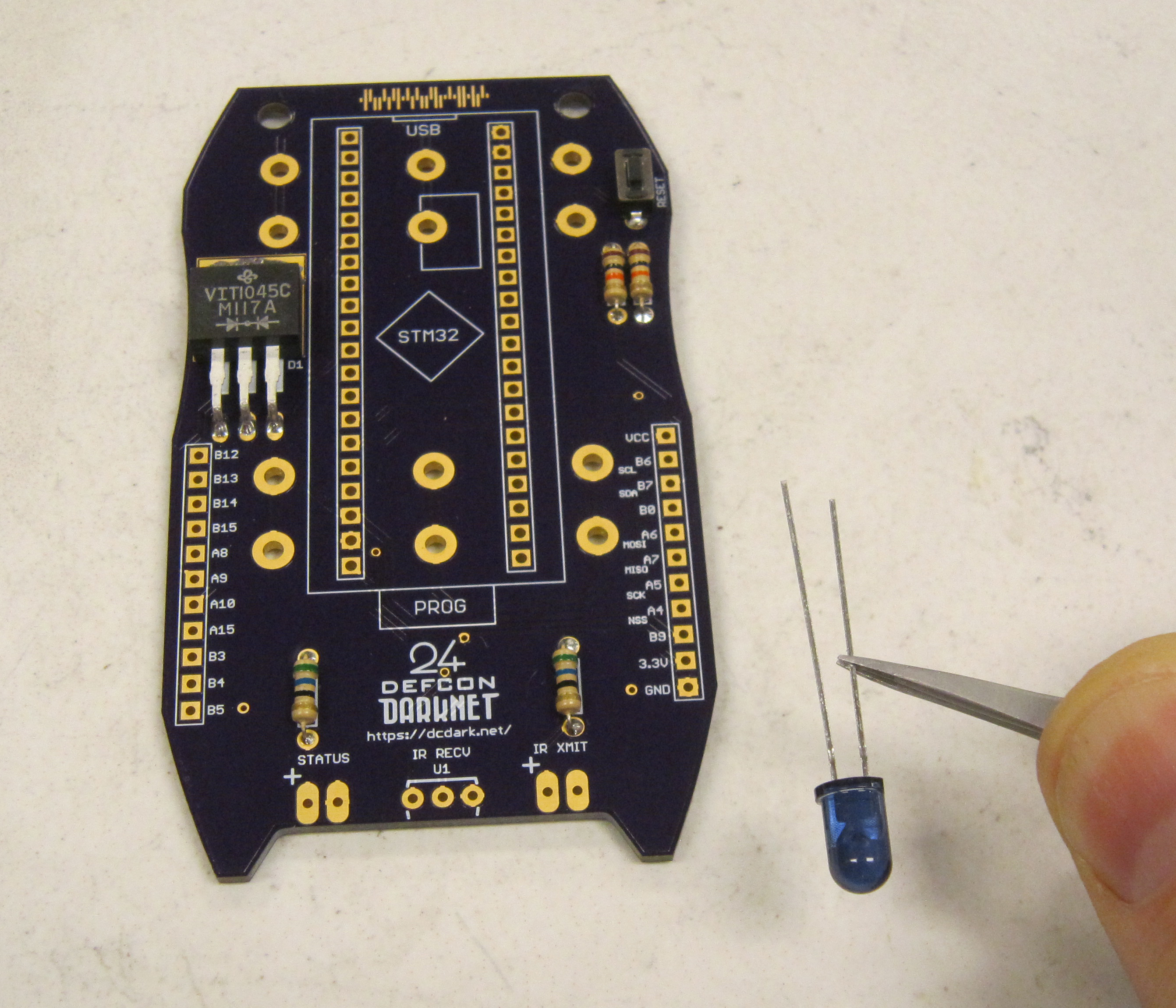
The second method is by determining the flat spot of the LED. This indicates the Cathode, or negative lead.
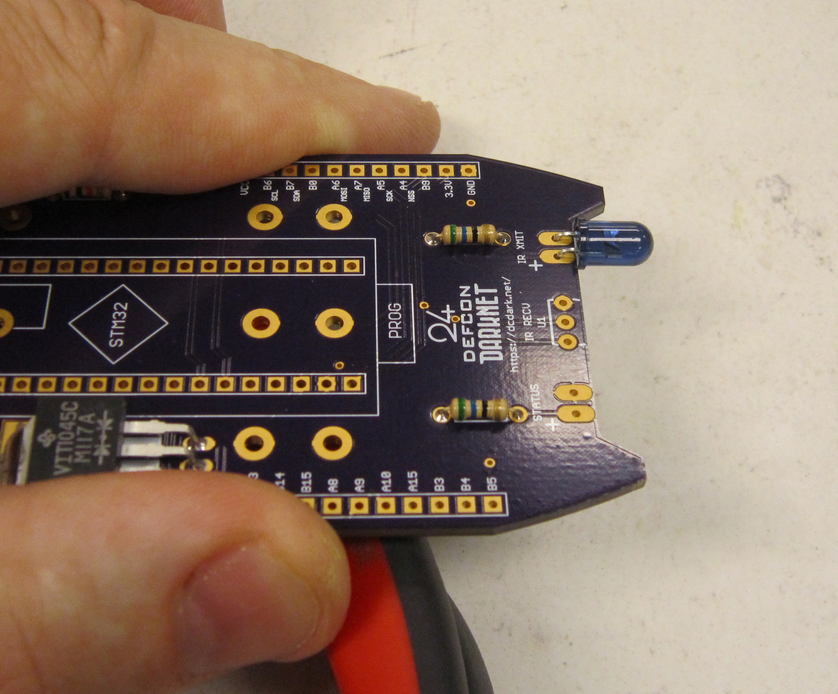
We will be installing the IR LED at IR XMIT.
The Anode is marked with a + to indicate the positive lead.
Bend the leads of the LED so that the case is flat pointing in the direction of the points on the board as shown.
There will be about 3mm of lead between the case of the LED and the bend.
Do not solder the LED so it is perpendicular to the board. This will be important later.
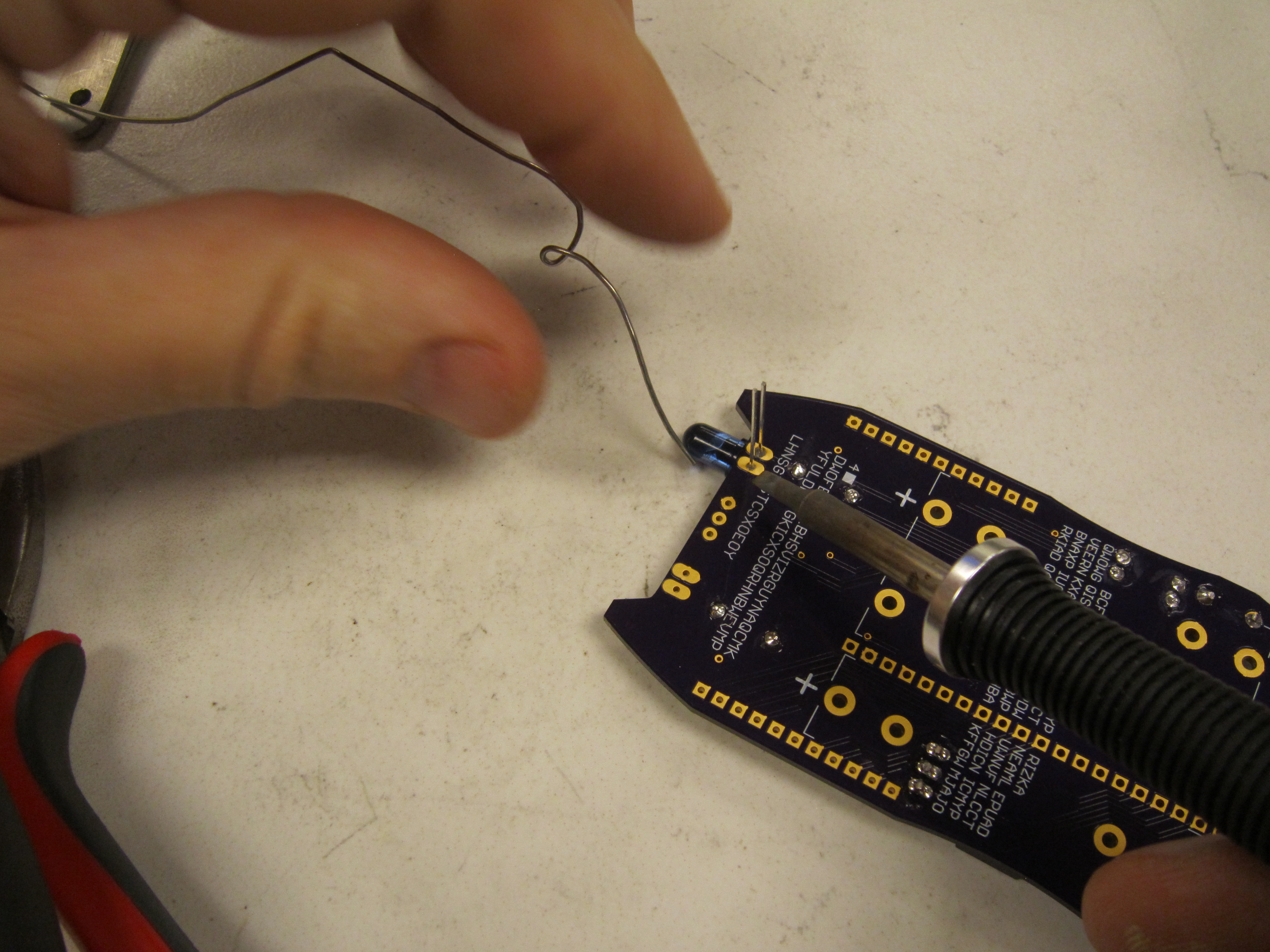
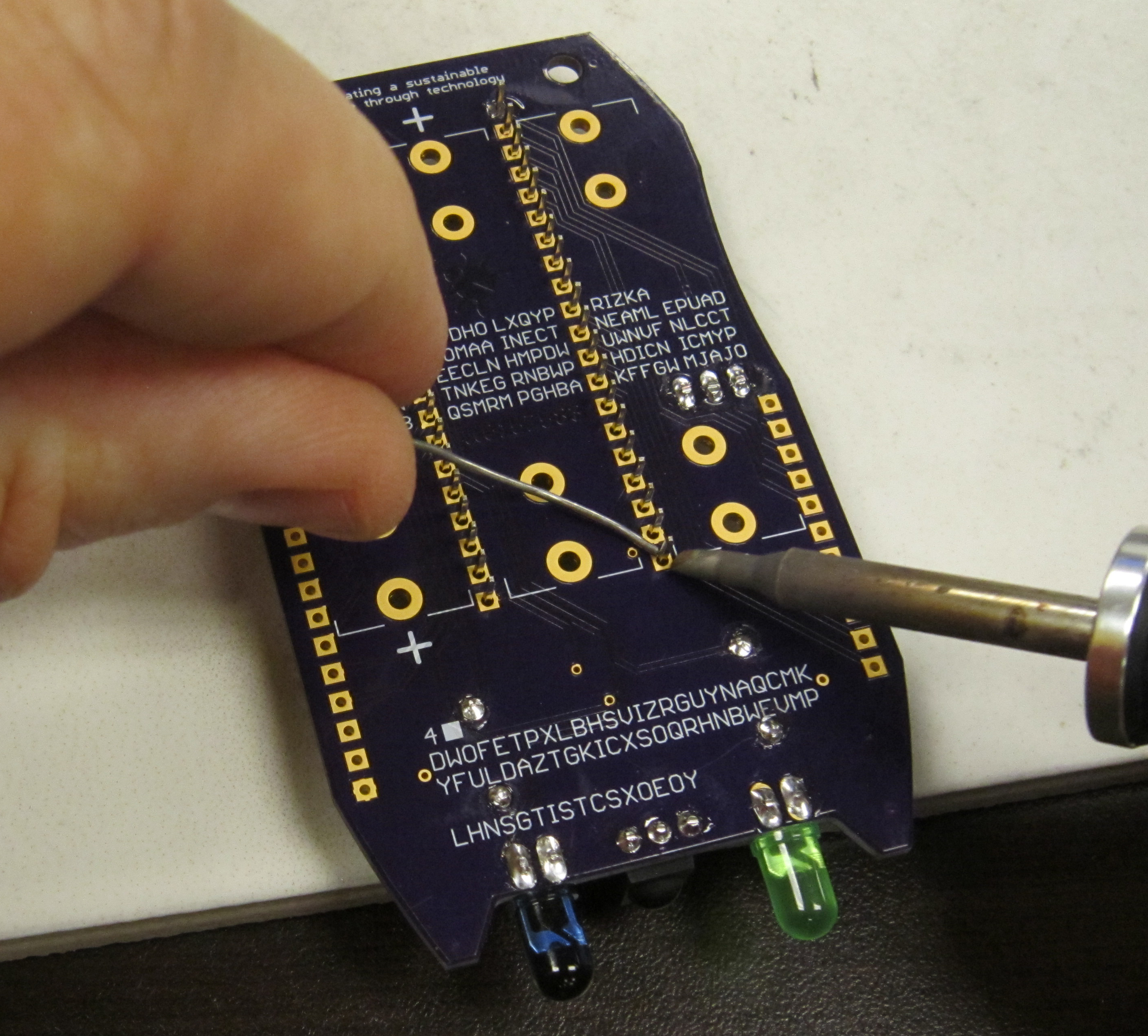
Solder the LED in place from the top side of the board.
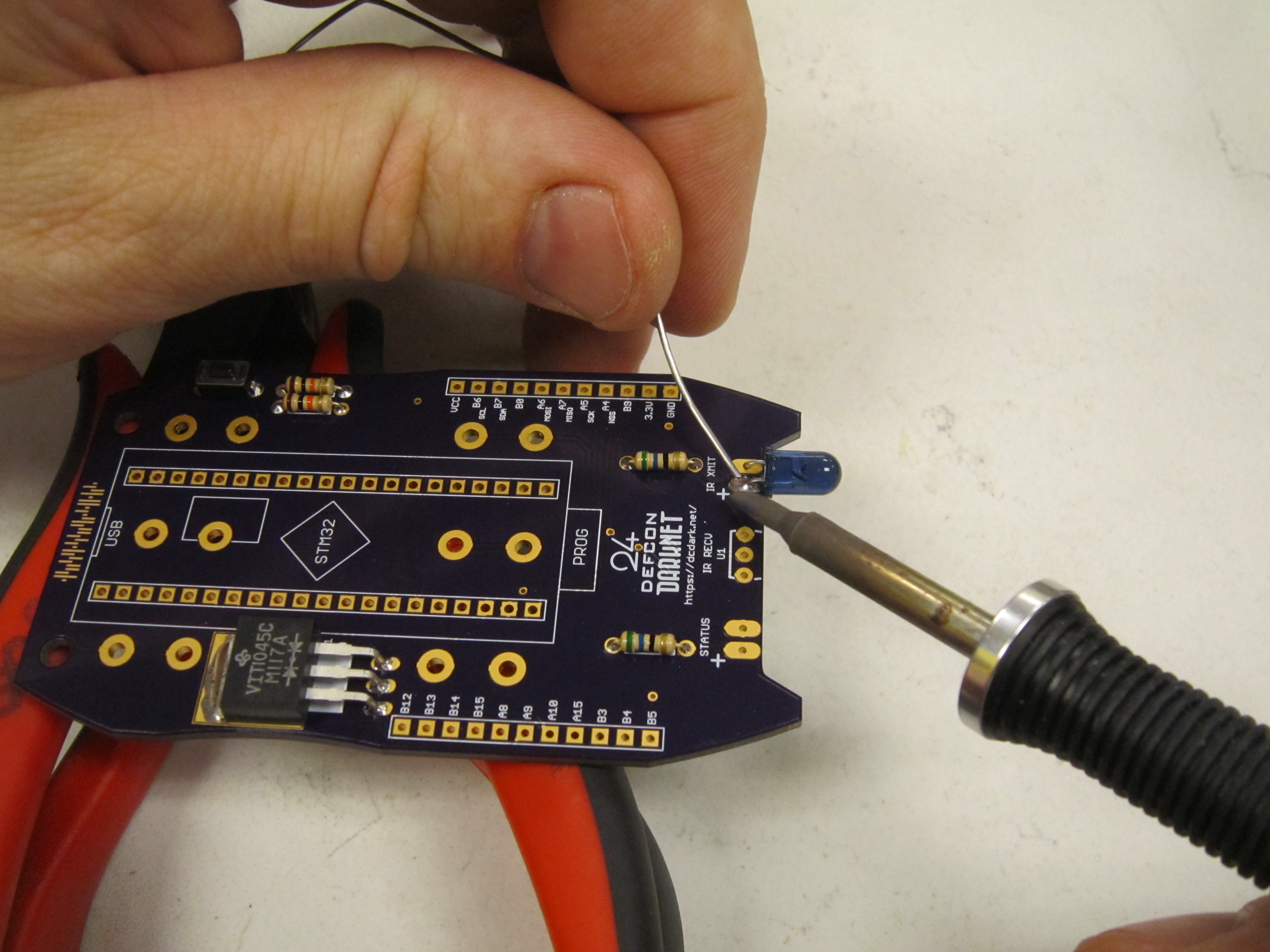
Next solder the leads of the LED on the underside of the board.
The next part is the Green LED, at STATUS. The long lead is positive.
Again, install the LED so that it is laying flat as shown. Soldering from the top of the board first, and then the underside of the board.
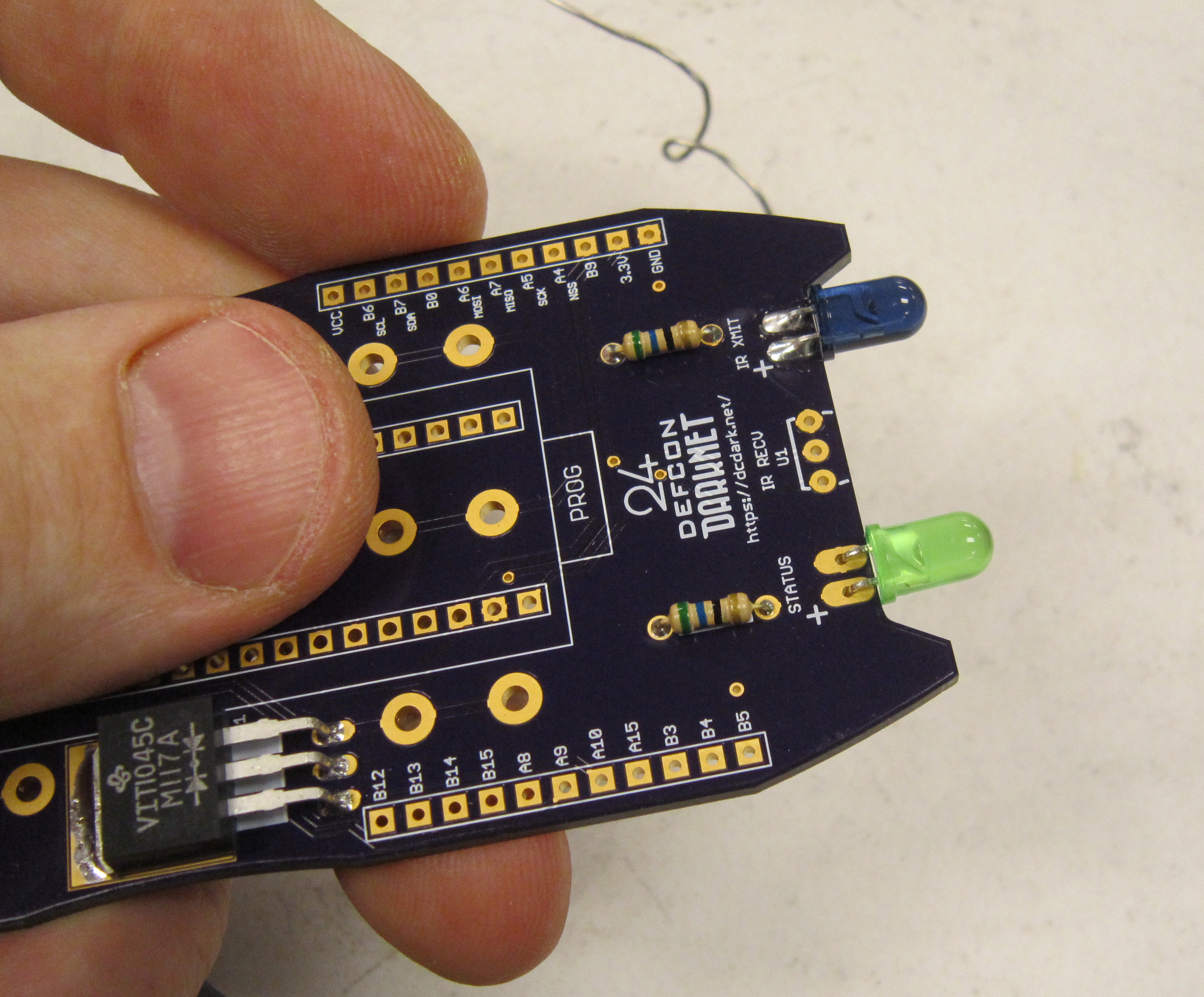
Finally trim the leads.
Now we add in the infrared receiver module. This component is polarized, and is installed in U1, so the dome is pointing toward the bottom of the badge.
Solder and trim the leads.
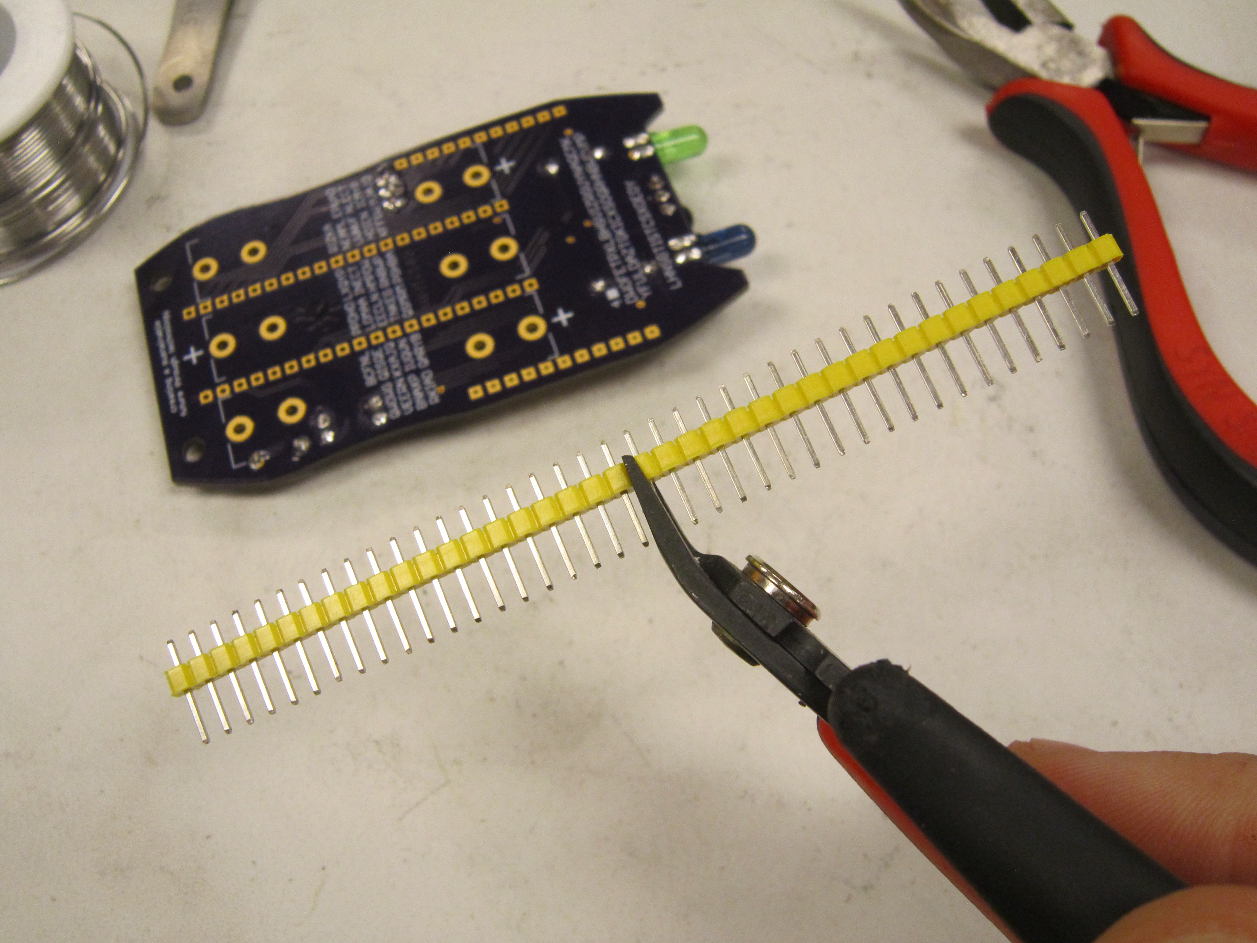
Here is a part where order matters
First find the yellow male header for the micro controller and cut the header strip in half. There are 40 pins, on the micro controller, so it will use the entire 40 pin header strip.
Install the headers in place on the main badge board. This order is important as the middle battery clips cannot be installed with the microcontroller in place. And soldering the microcontroller headers in place is very difficult once the battery clips are in place.
Insure the headers are flush to the PCB.
Solder the two end pins first.
Double check that the headers are still flush. If you need to ajust you can melt the solder joint at the end which needs moved, and fix before soldering the remaining header pins.
Solder the remaining pins and then trim flush, being careful to hold the leads of the pins as you cut them to prevent stray metal leads from turning into projectiles.
Next we install the female headers. These will be cut into two 11 pin strips.
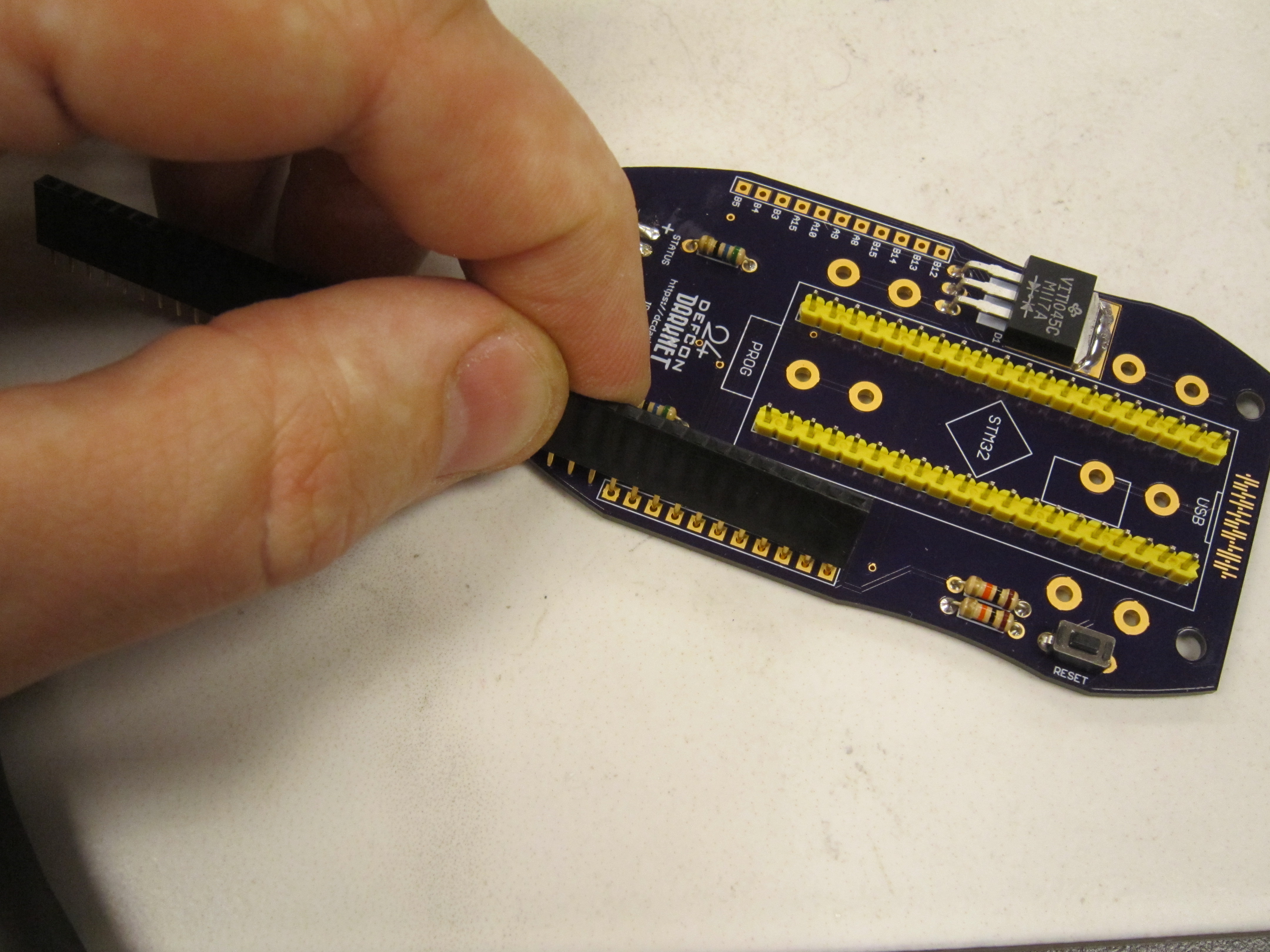
Unlike make header strips, when cutting female header strips, you lose one pin in the process as you have to cut along the pin line.
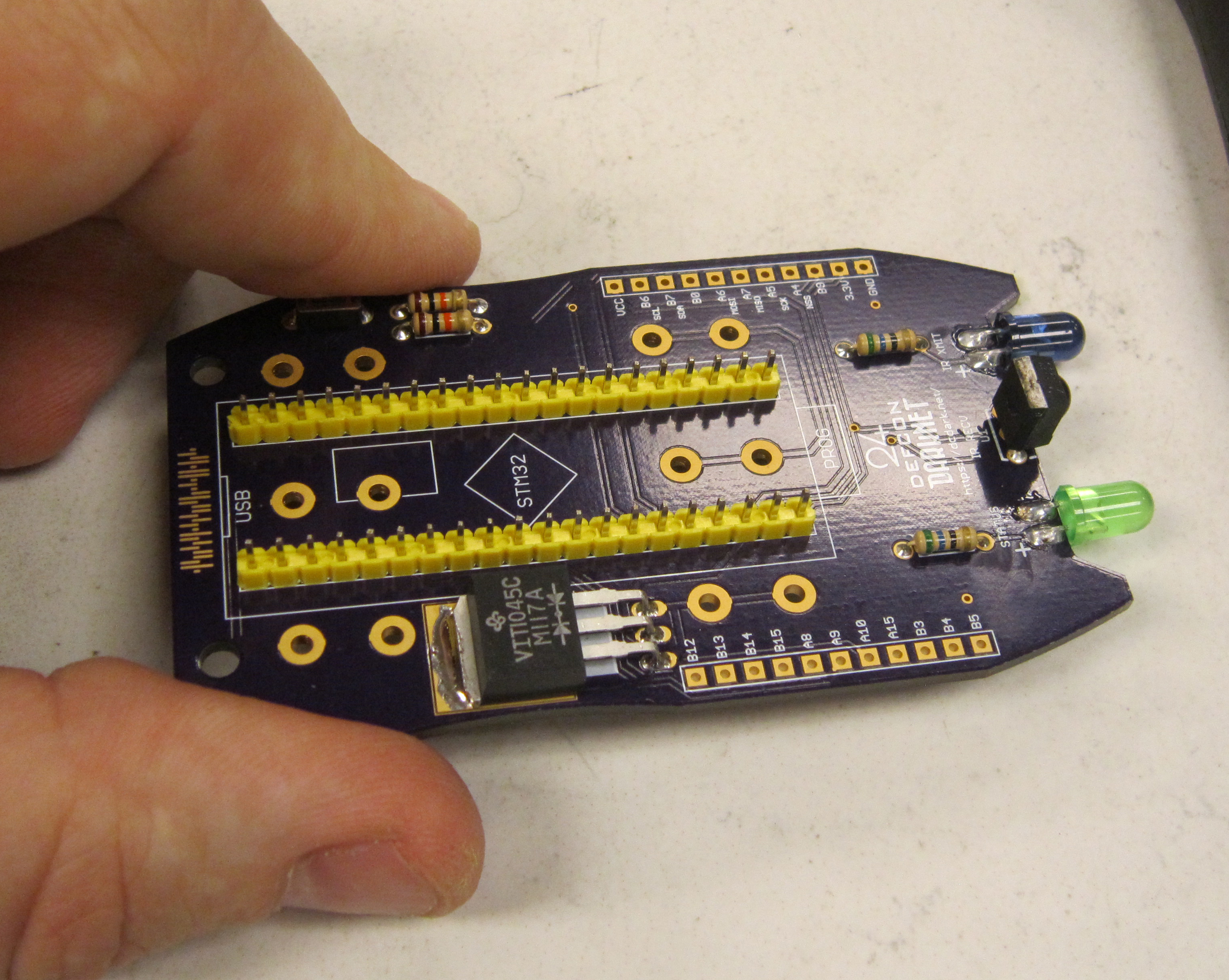
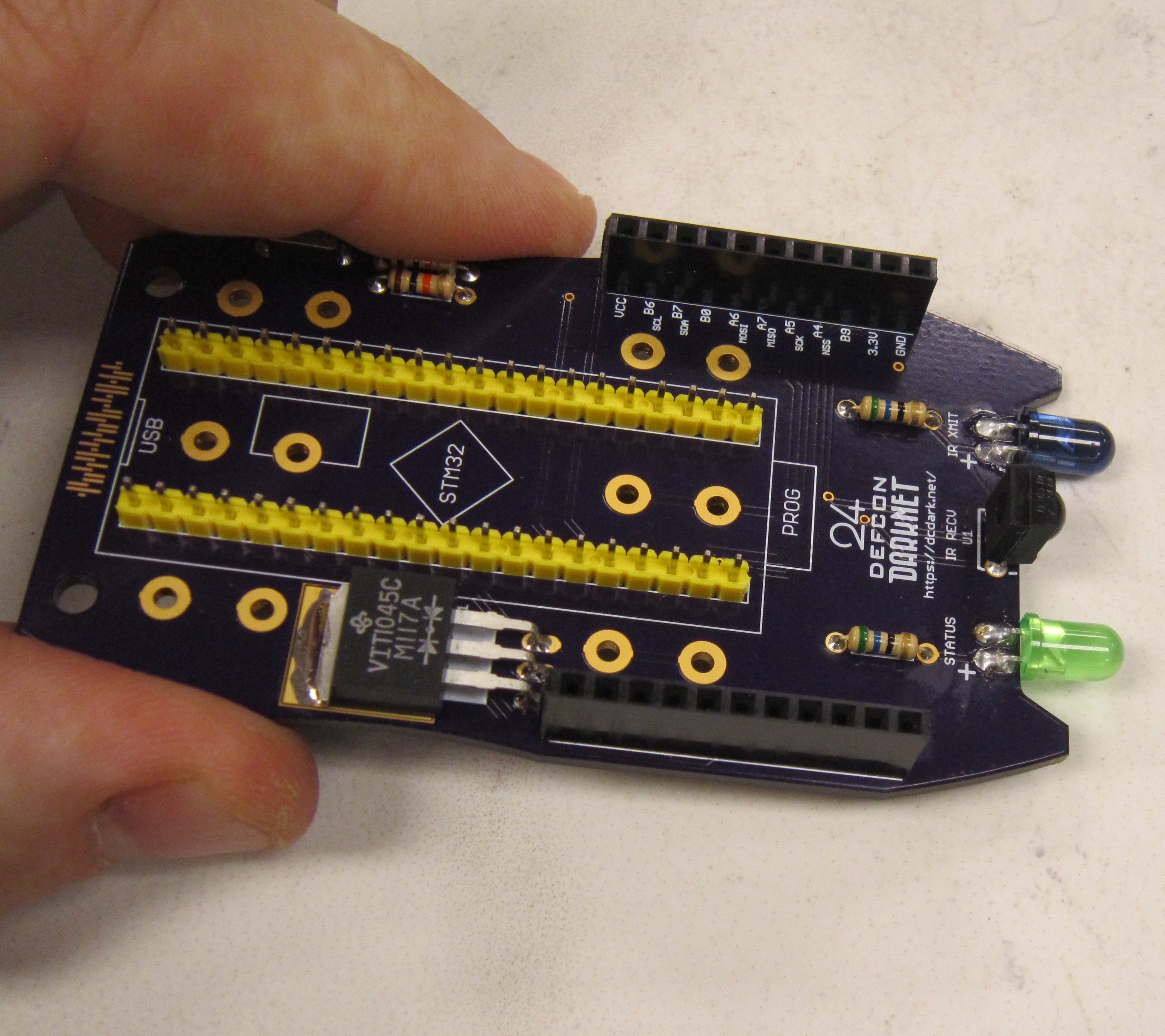
Solder these headers in place using the same method uses for the male headers. When completed your board should look like this:
Next install the two microswitches, SW1 and Reset. These components are not polarized, and may be installed in either direction.
The USB button, when pressed will have your badge emulate a keyboard device.
The reset button resets the badge, and is also used to cycle between modes.
Solder and trim the leads.
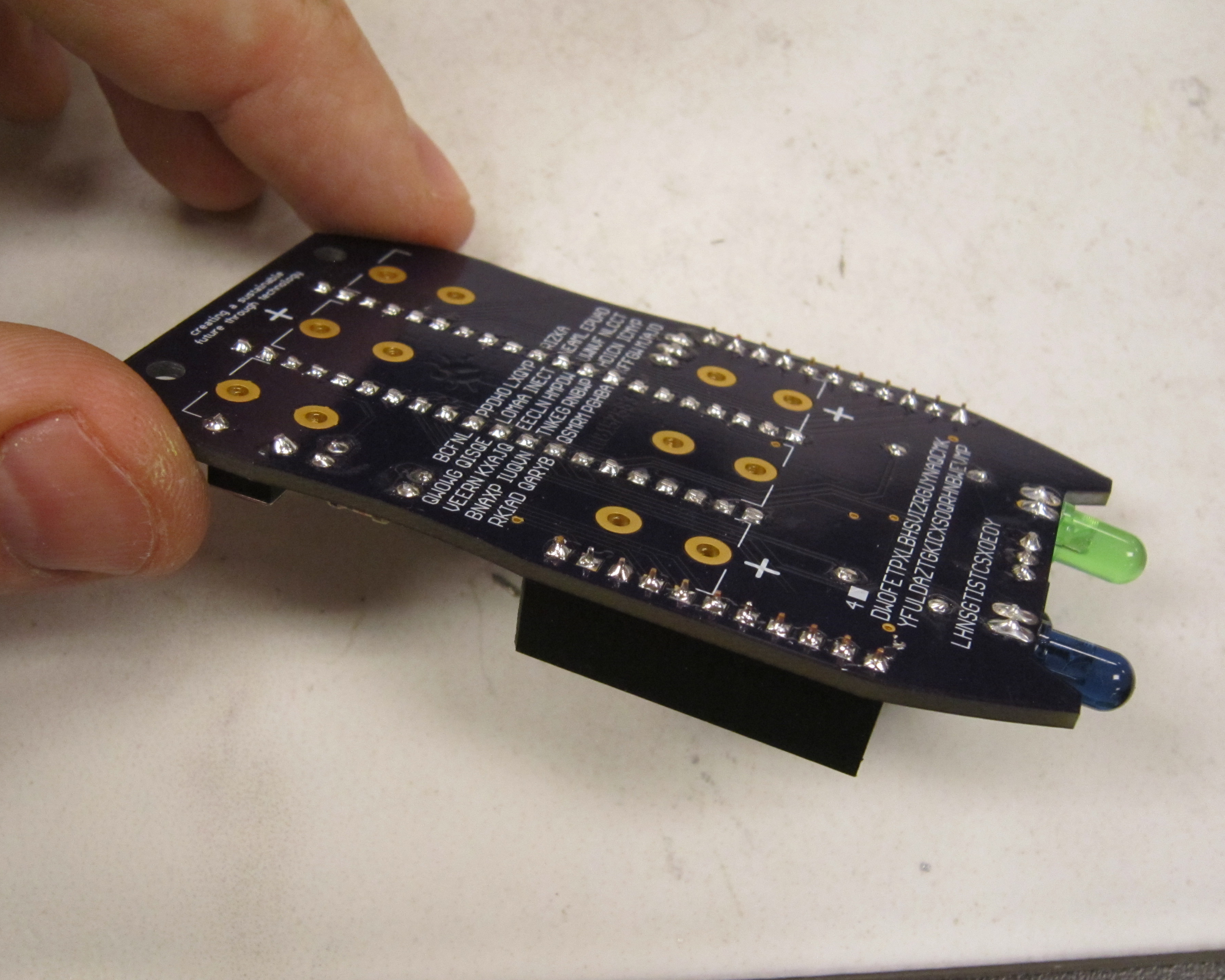
Next snap in the six battery holders. Ensure they are flush with the PCB.
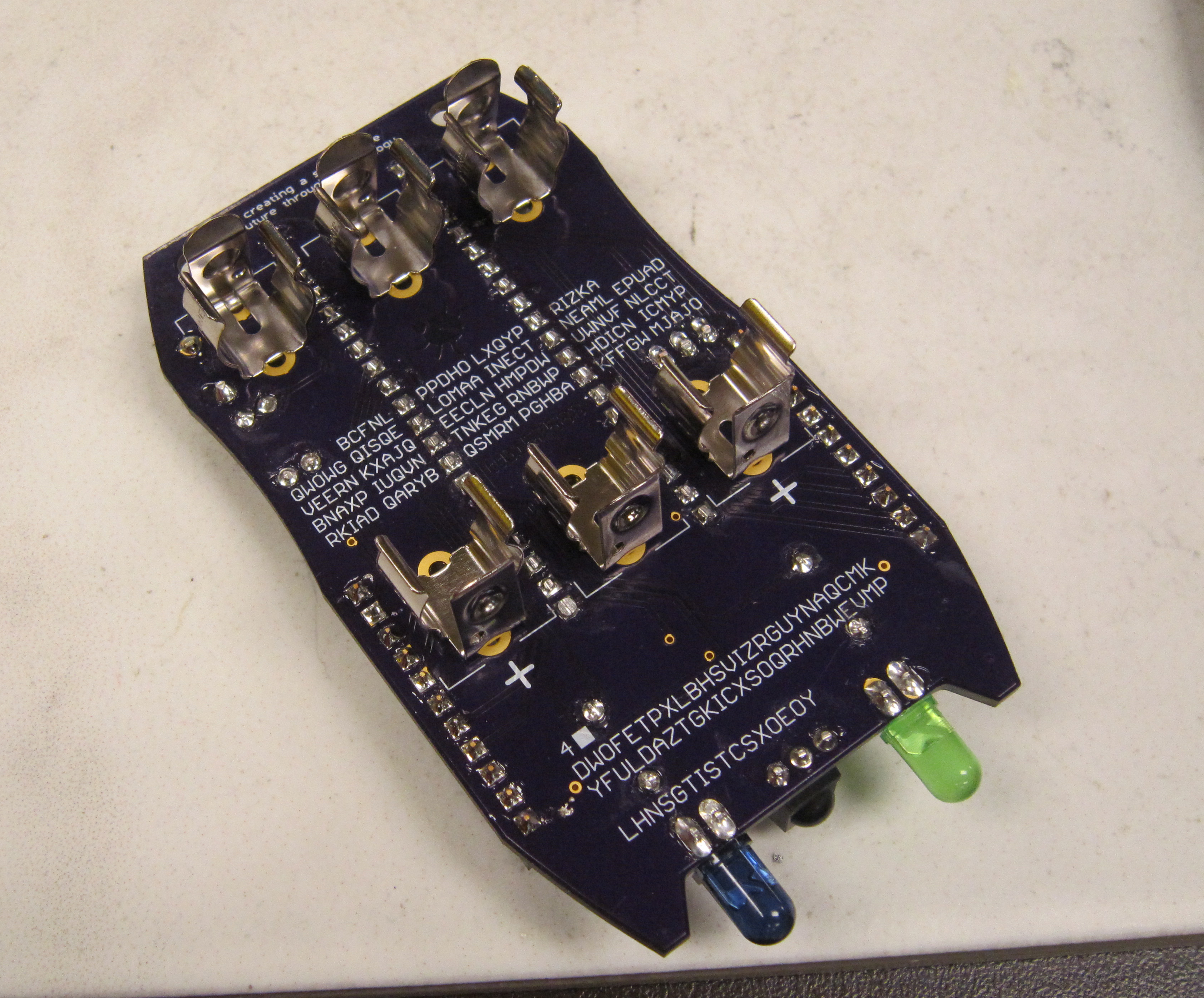
Solder each of the tabs, ensuring to heat both the pad and the battery holder tab.
Trim flush the battery tabs which will be located under the microcontroller
Now is a really good time to get the firmware loaded on your microcontroller if you have not done so already.
Next place the micro controller on the male header pins soldered previously. Note the orientation. The USB connector should be located at the top of the board, and the programming header should be located at the bottom of the board.
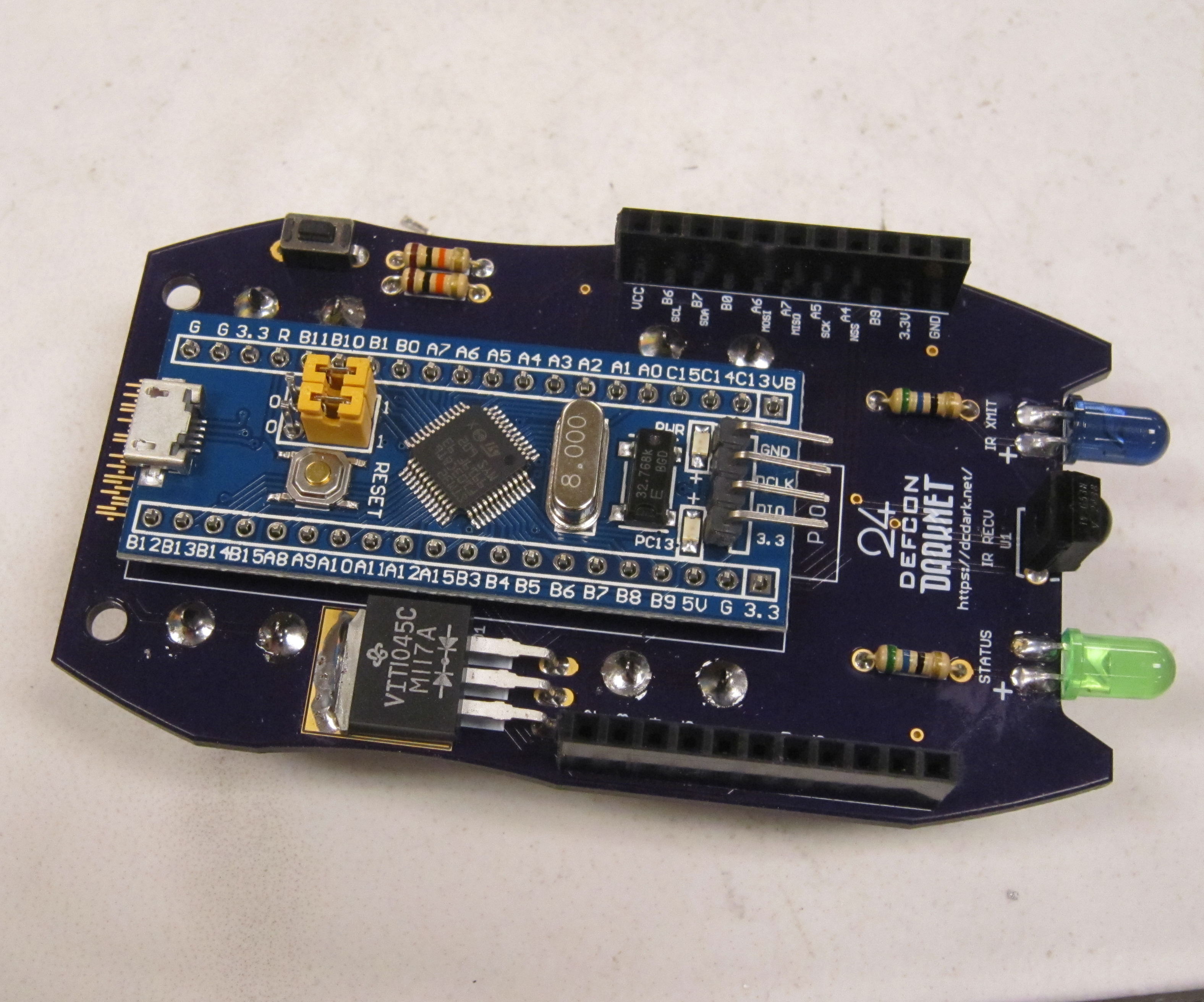
Solder in place.
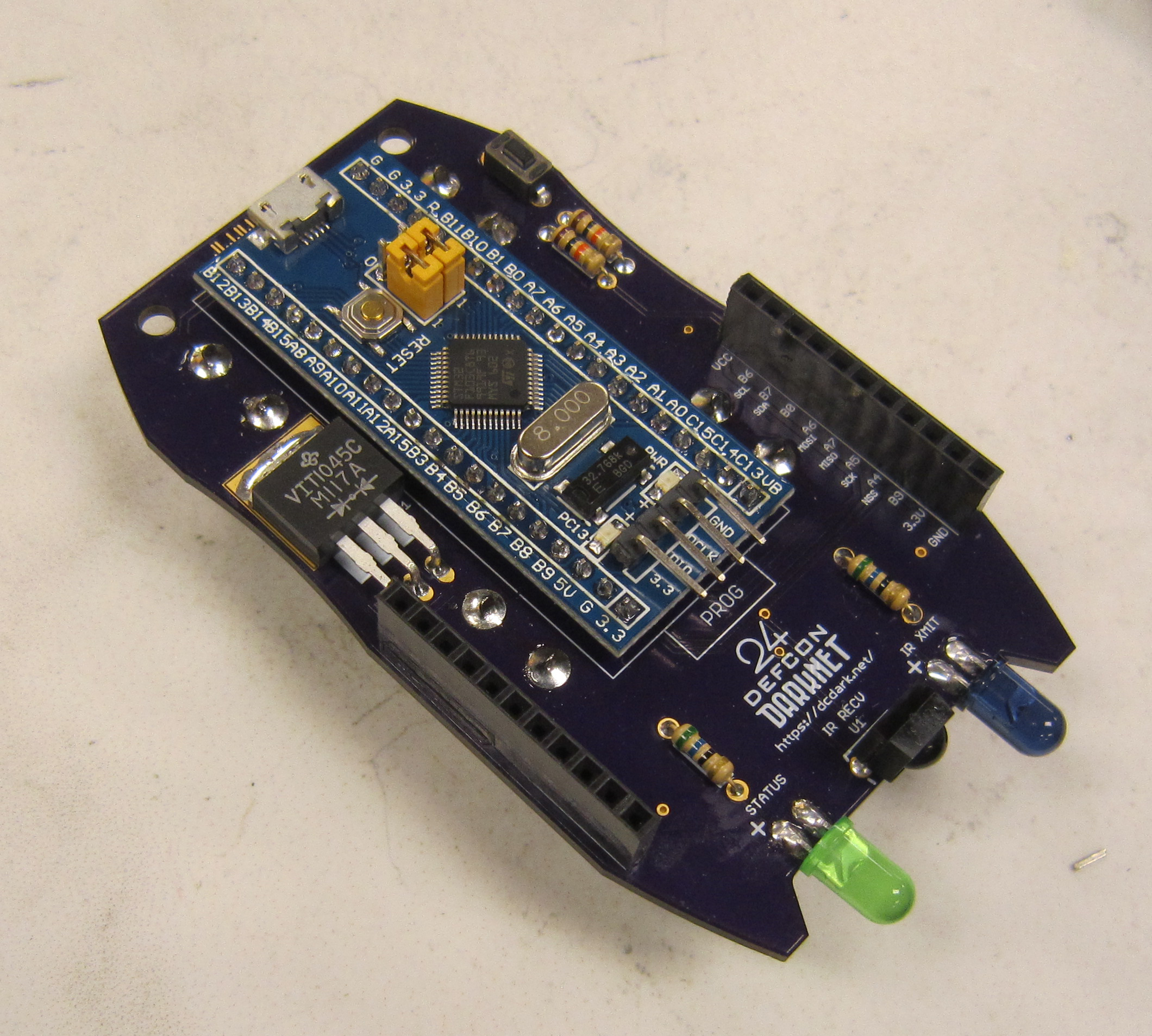
This completes the lower PCB.
This next part is a choose your own adventure.
The shield board holds the LED back lighting, the T9 keypad, the OLED display module and the radio module.
While the push button switches, OLED module, and headers are all through hole, the remaining parts are surface mount.
You have several options:
Note that once you have hand soldered components, you are unable to use the solder paste stencil for reflow soldering.
This how to will cover hand soldering all the components. The LEDs are soldered in place so they shine through the PCB substrate to illuminate the letters when viewed from the front of the board.
While tricky, surface mount soldering can be done easily using the following techniques.
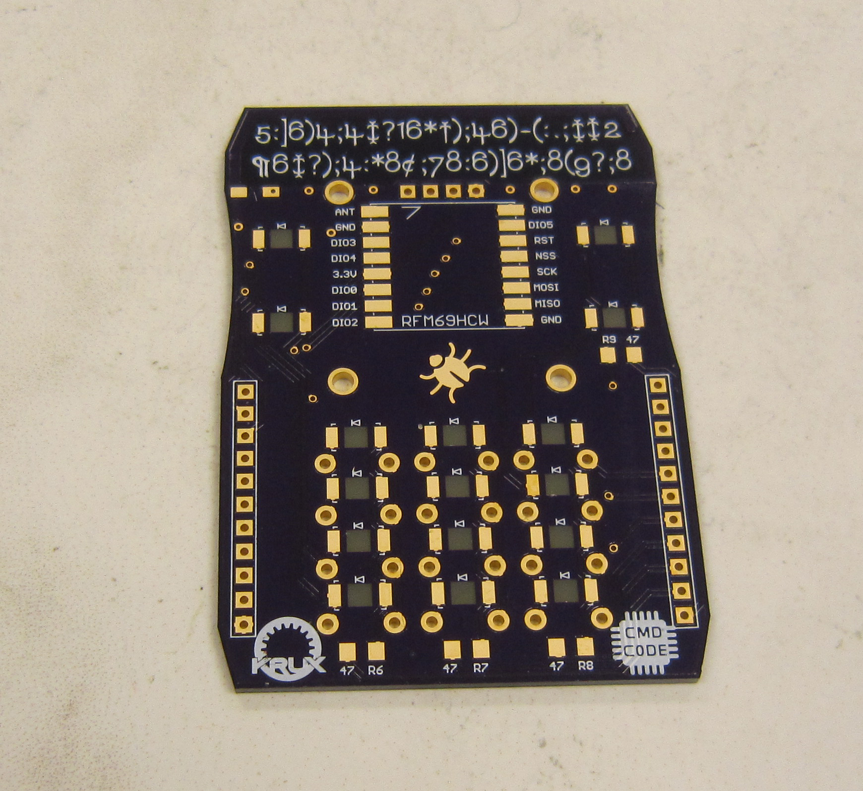
First we will install the 47 ohm resistors R6, R7, R8, and R9. Apply solder to one of the pads.
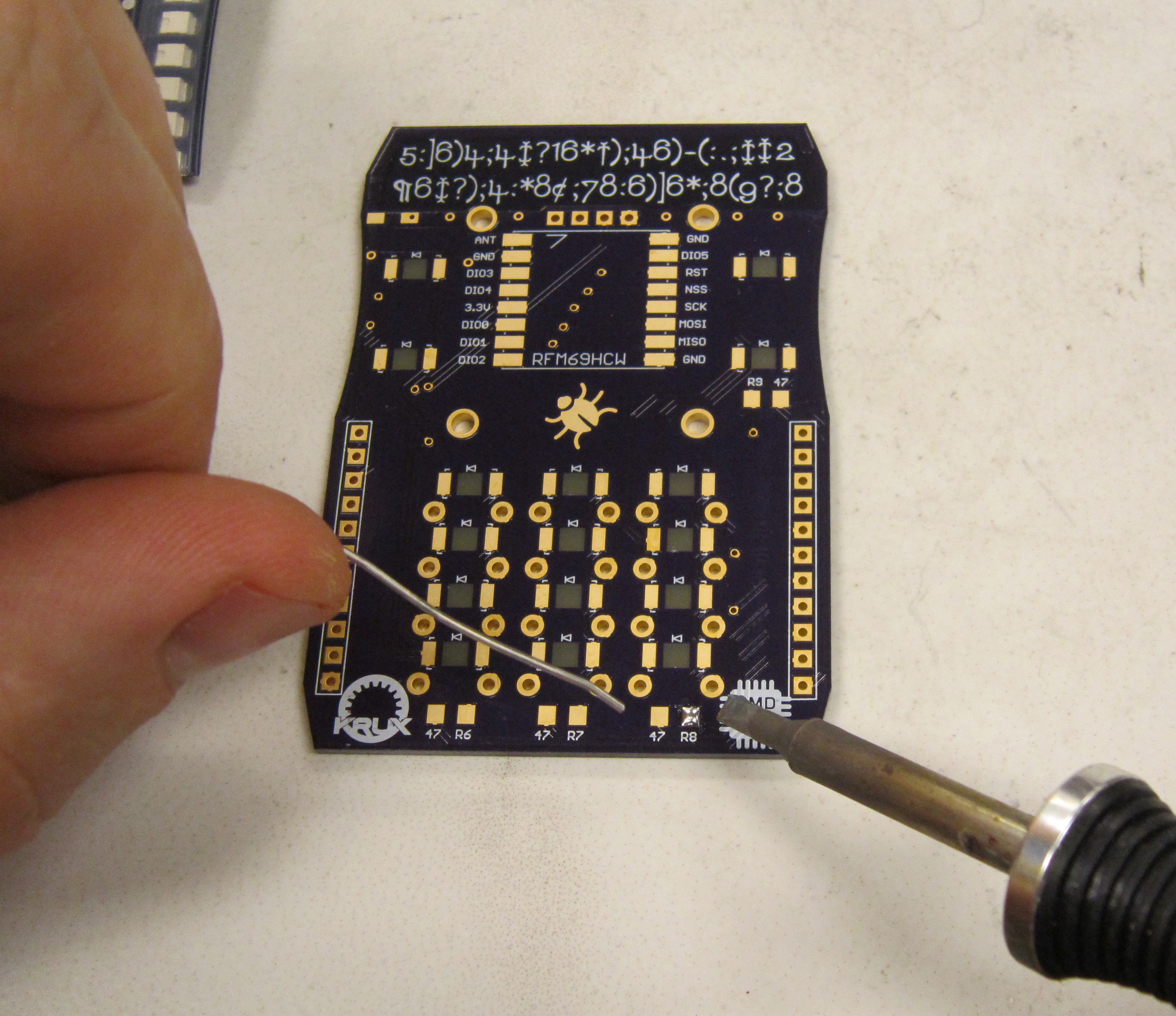
Using tweezers, pick up one of the resistors and guide it in place while heating the solder on the one pad, then remove the soldering iron while continuing to hold the part in place. Remember that surface mount components are small and light, and do not require much force to manipulate. Using excessive force to pick up SMD parts with tweezers can result in "Gone Forever Syndrome" or GFS, as your component flys across the room. Spare components are on hand, but do try to be careful.
If needed the part can be adjusted by melting the solder and moving it carefully with the tweezers. It often helps to use magnification for this step.
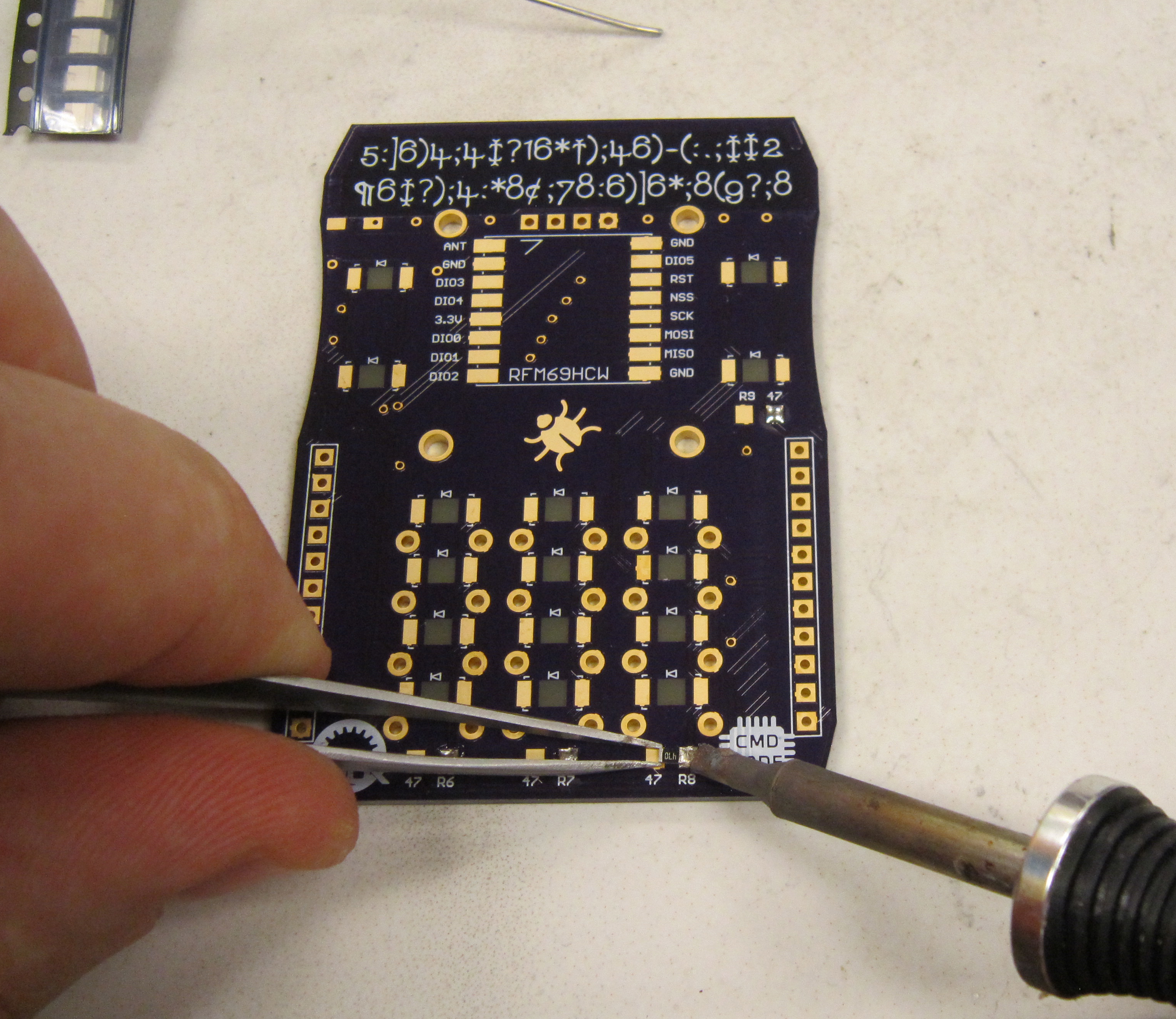
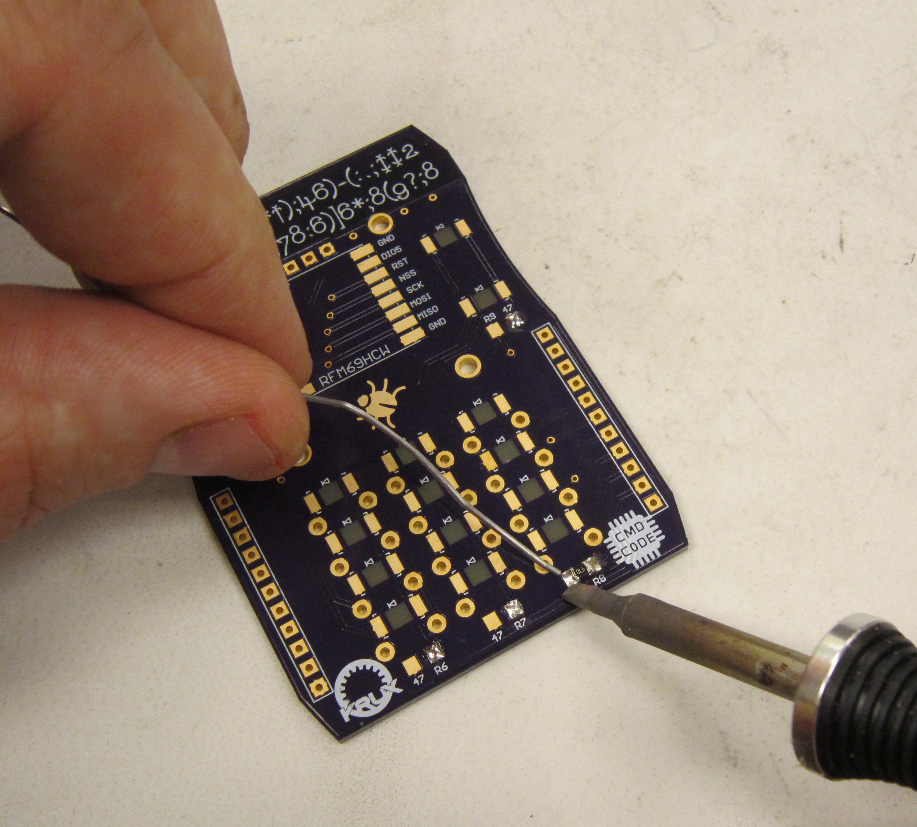
Next solder the second pad of the resistor.
Repeat this process for each of the surface mount resistors.
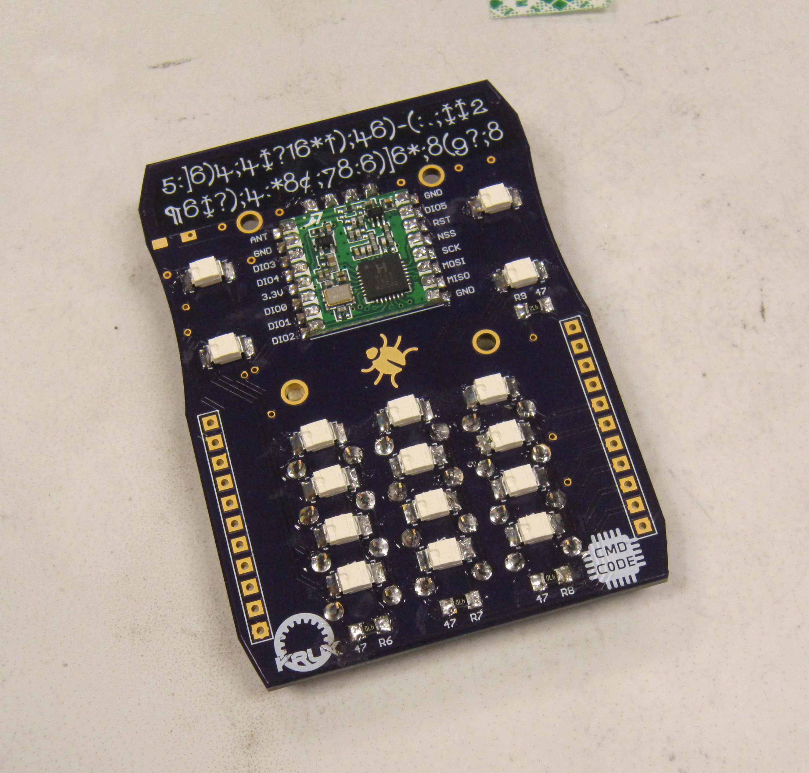
The LEDs are soldered in the same method the resistors are soldered. However the LEDs are polarized, so they will only work if installed in the correct orientation. In this instance, the cathode, or negative lead is marked by a dimple. As you are looking at the board with the bottom toward you, the dimples will point toward the left.
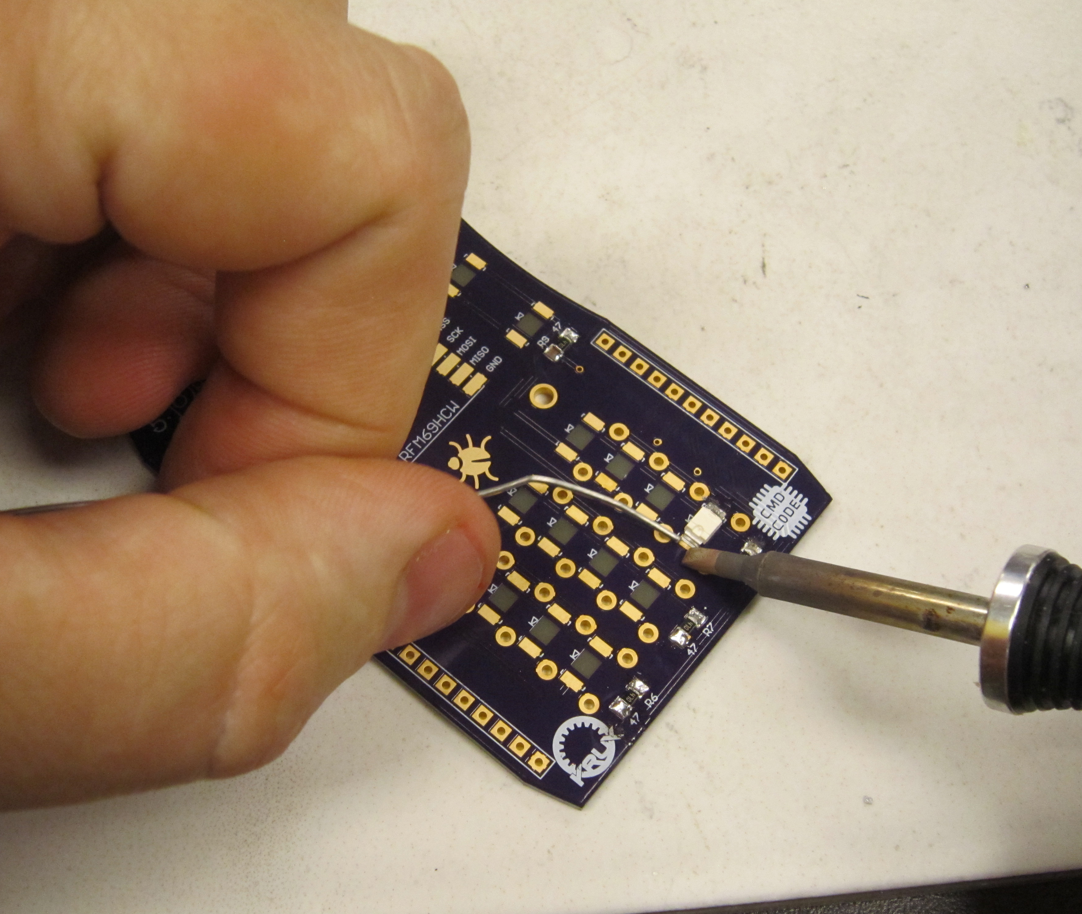
Again solder one pad.
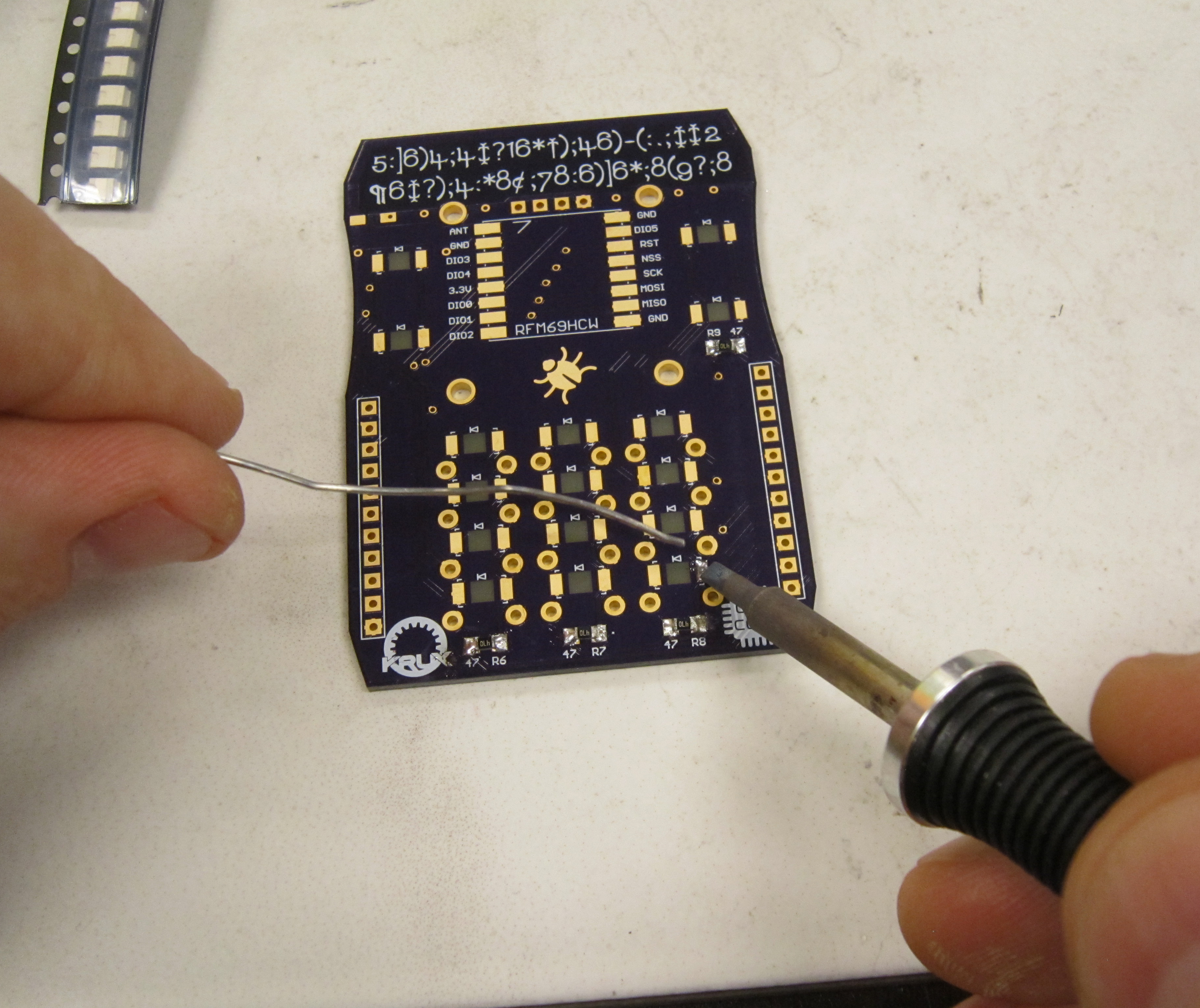
Use tweezers to guide the part in as you heat the soldered pad.
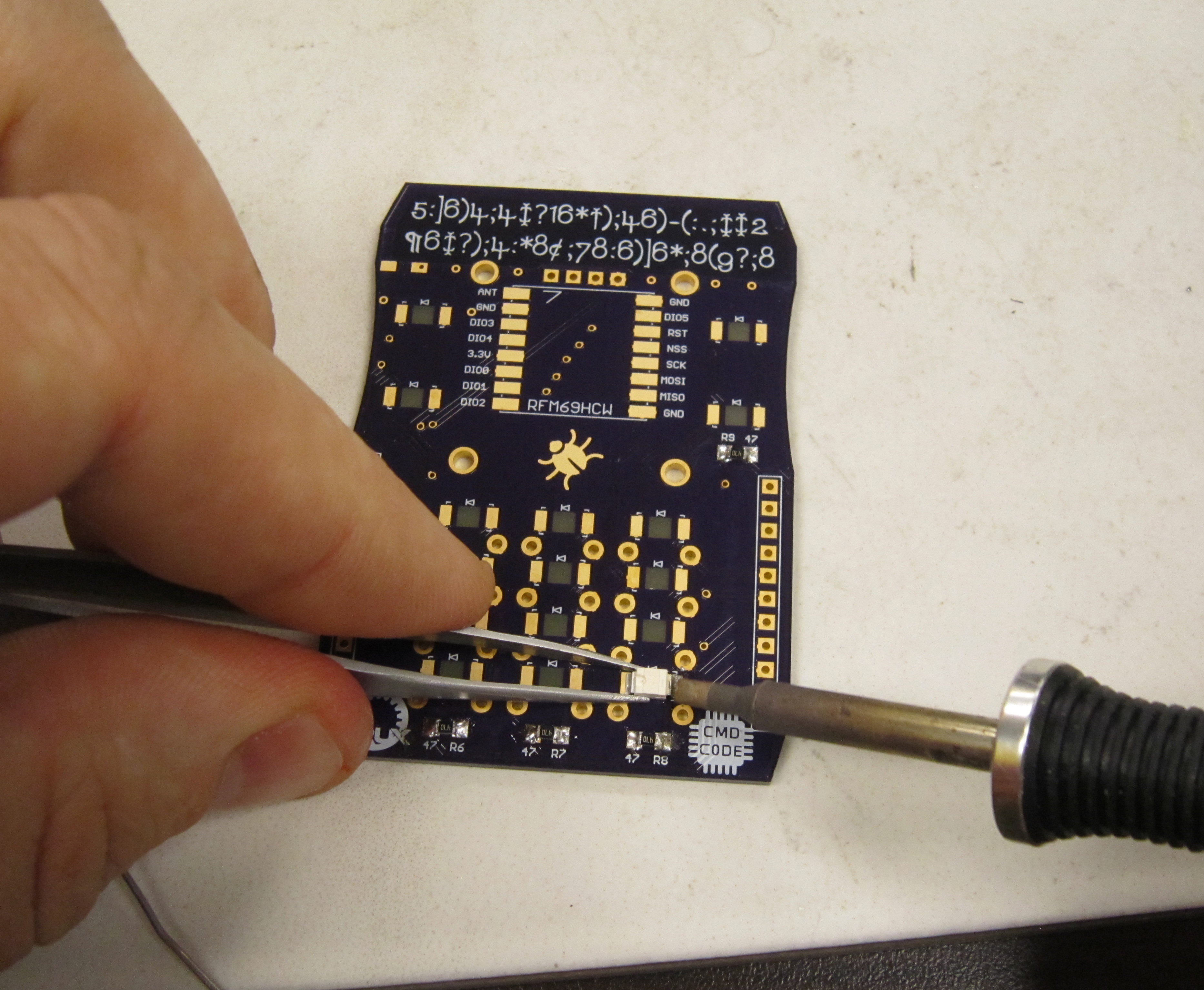
And then solder the remaining pad.
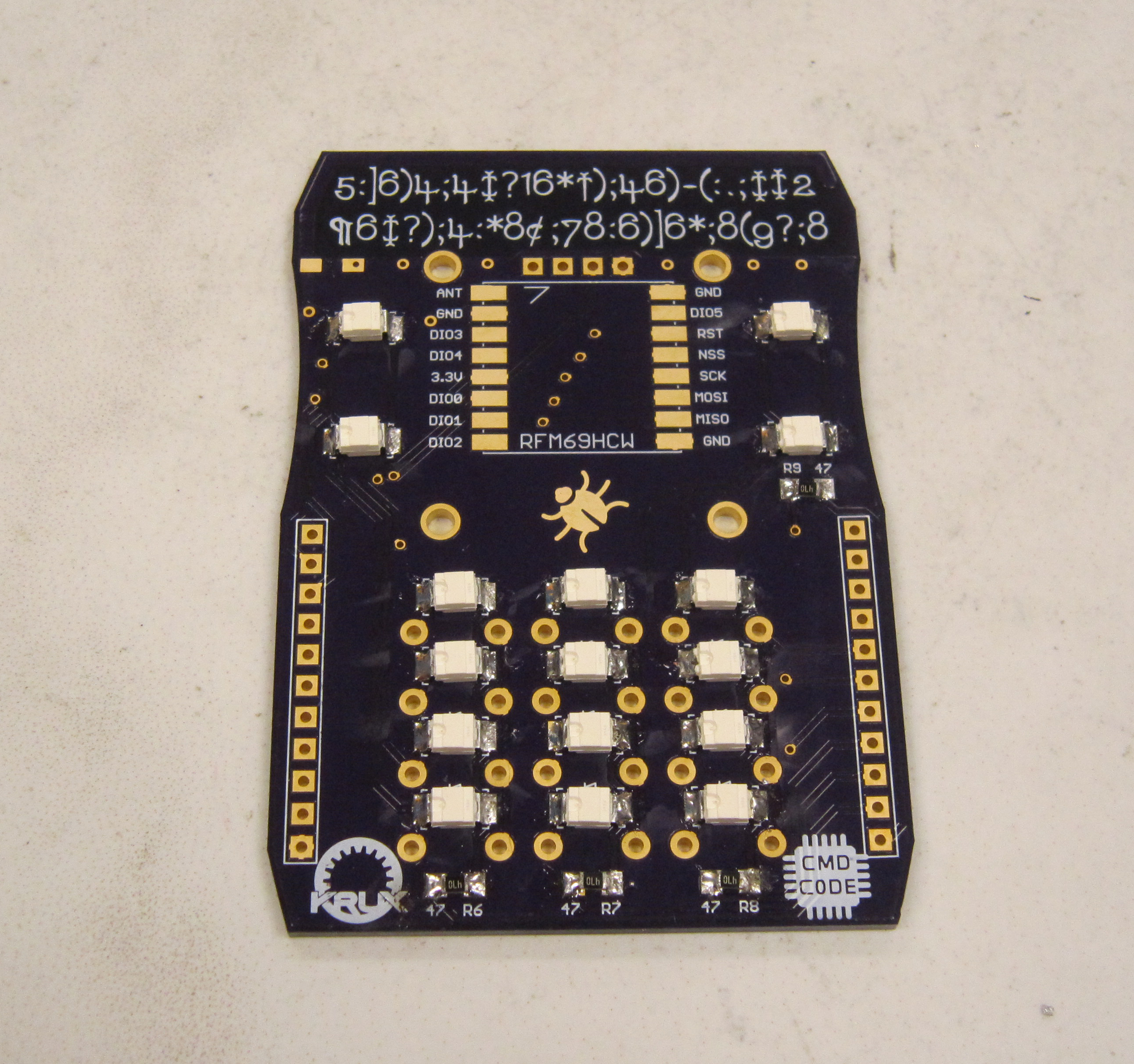
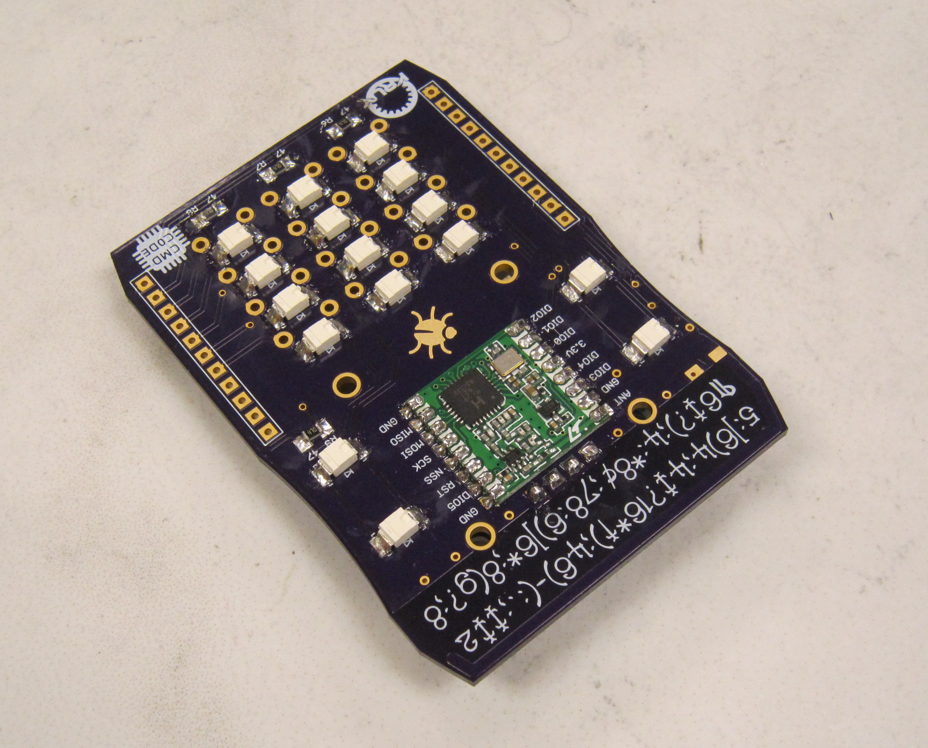
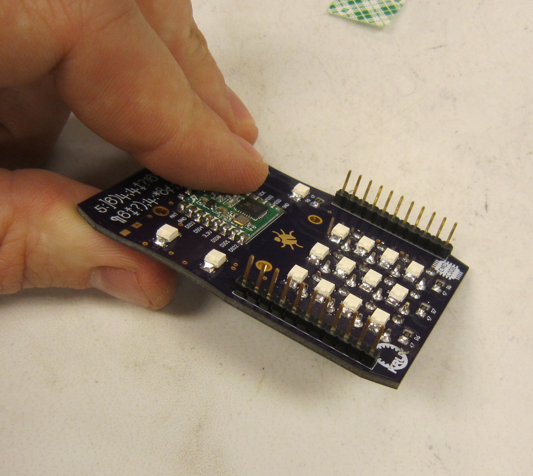
You should have a board that looks like the following:
New to this year is a radio module to allow longer distance communication with fellow agents. The orientation of these modules are indicated by a mark where the antenna pin is located.
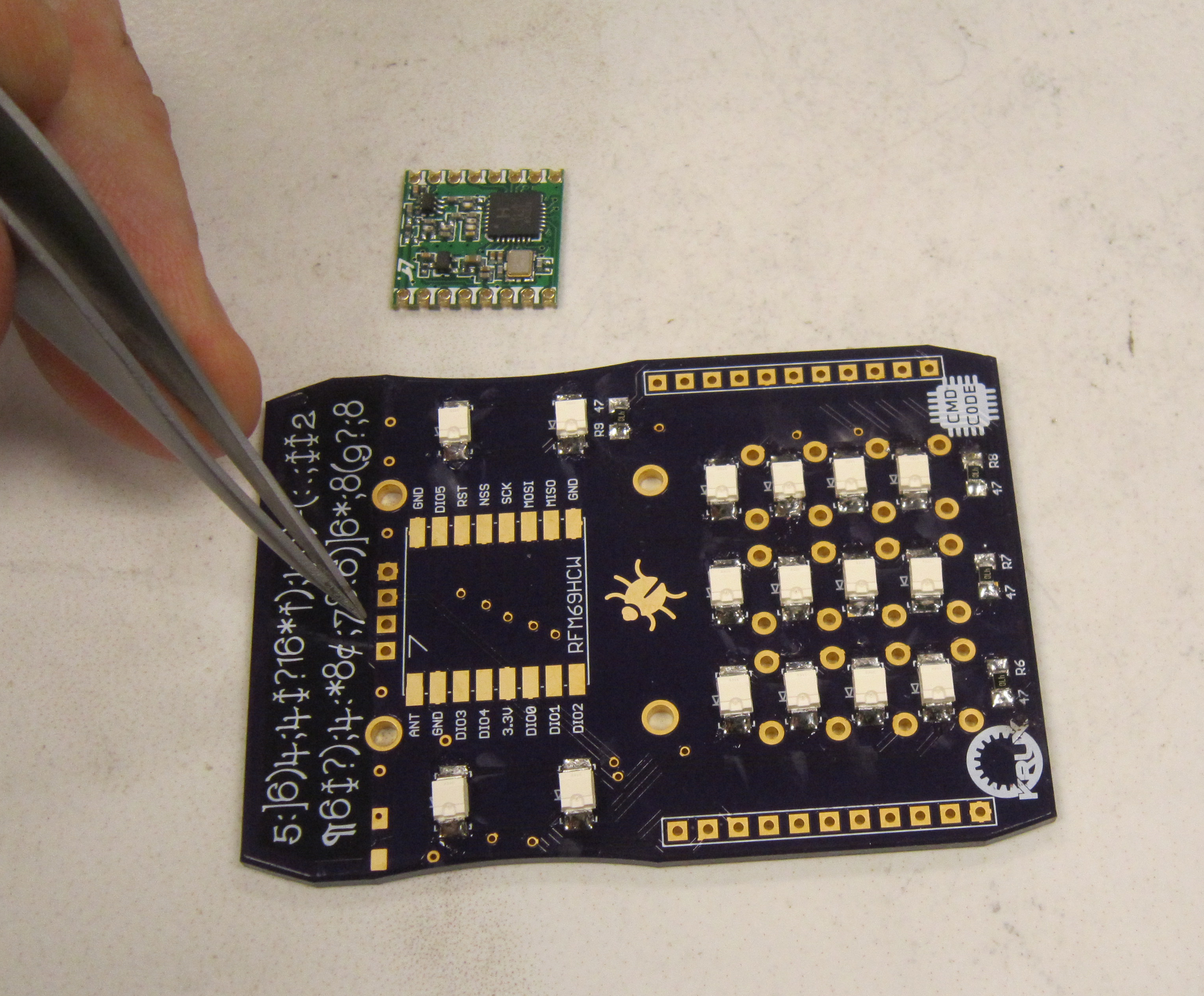
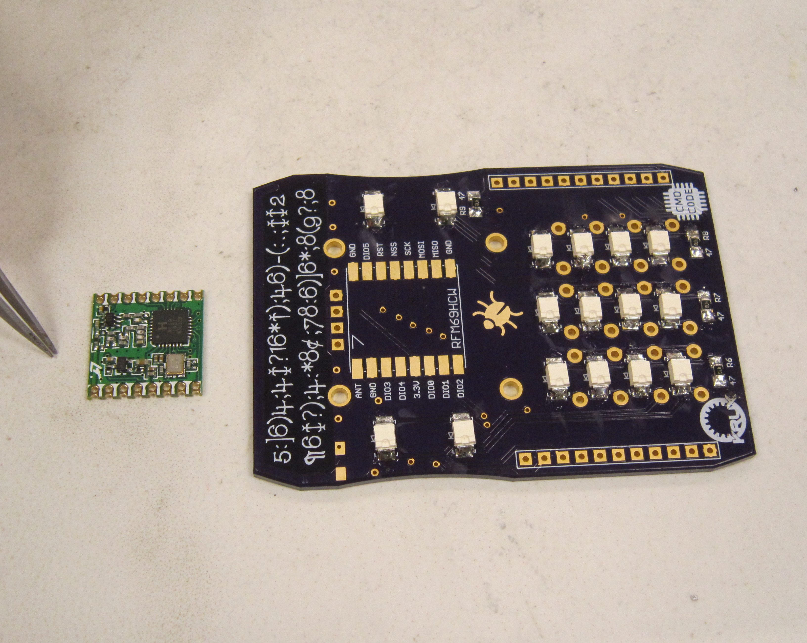
Start by using the same method for the other SMD components. Place solder on one pad.
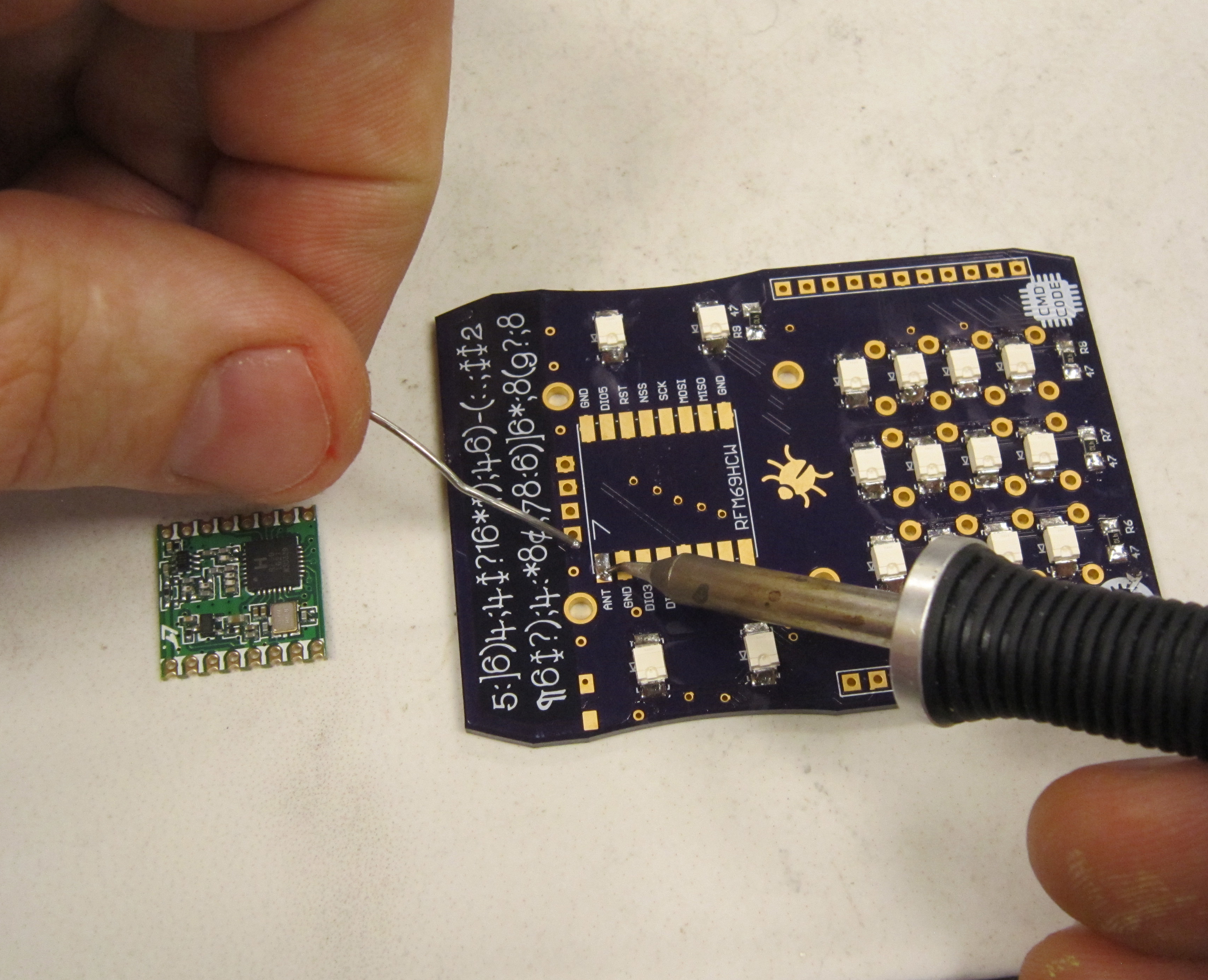
While heating the soldered pad, guide the radio module in place, and ensure it is oriented correctly and centered.
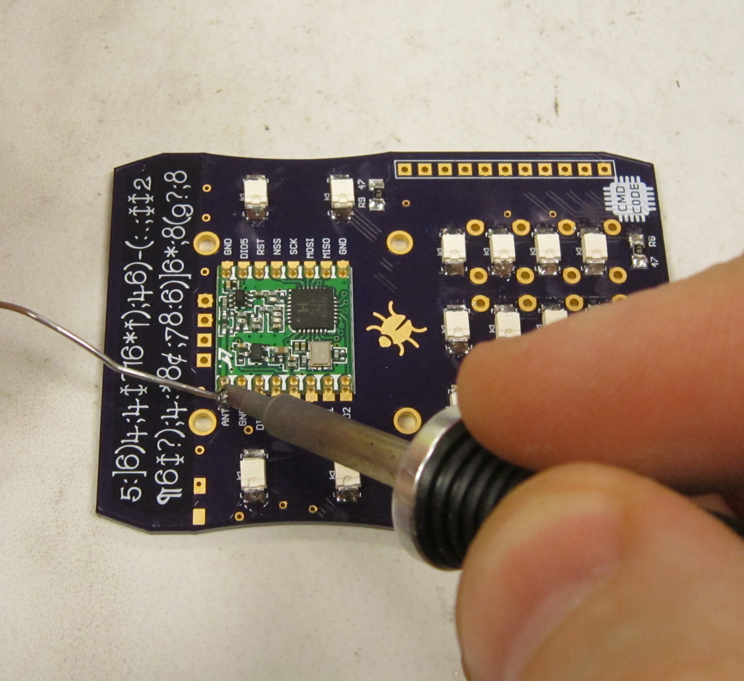
Next solder the opposite corner. To solder the radio module the soldering iron has to heat both the pad on the shield board, as well as the pad on the radio module, add a small amount of solder and it should flow into the joint smoothly if both pads are hot.
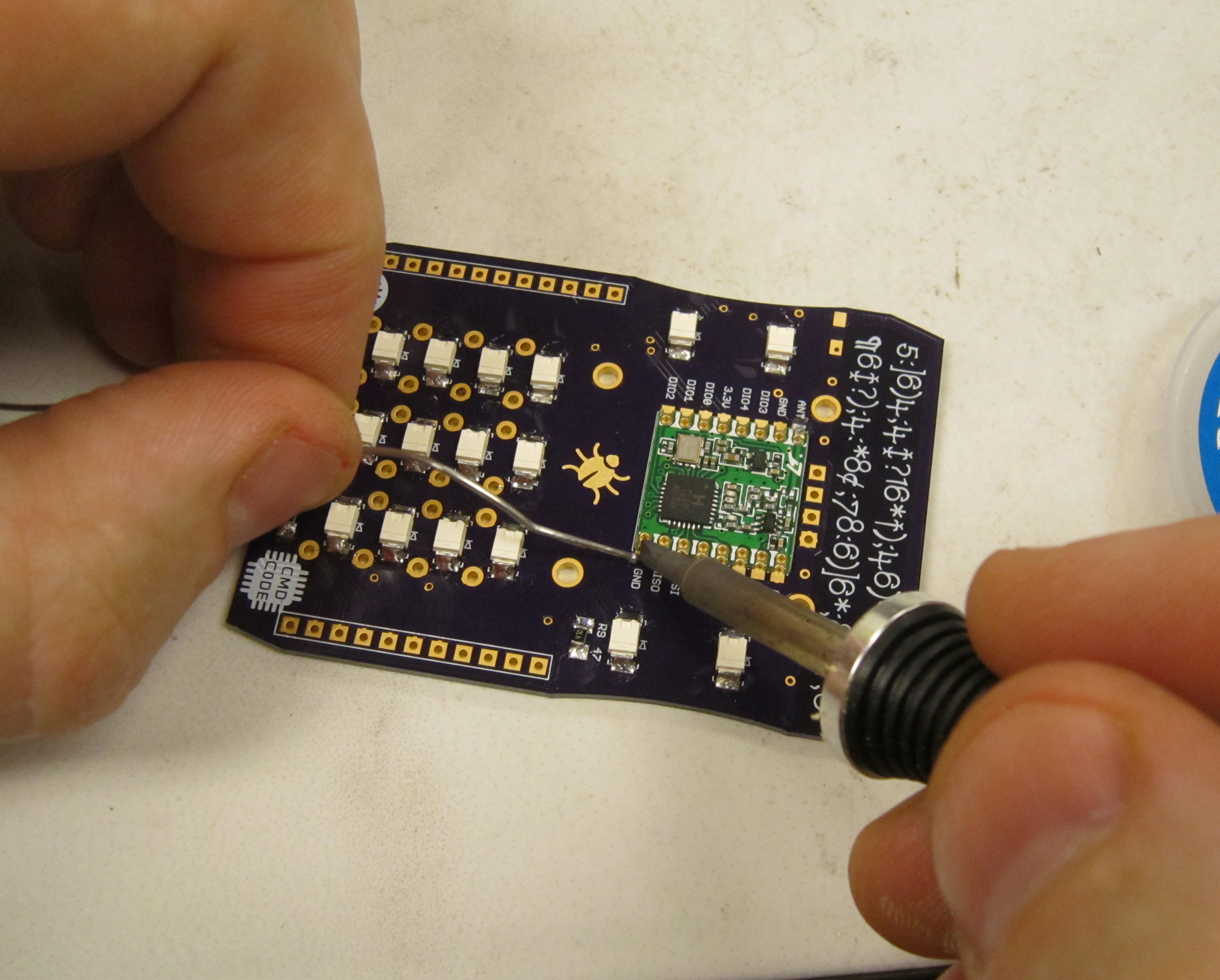
After double checking that the radio module is oriented correctly, aligned and centered on the pads, solder the remaining pads.
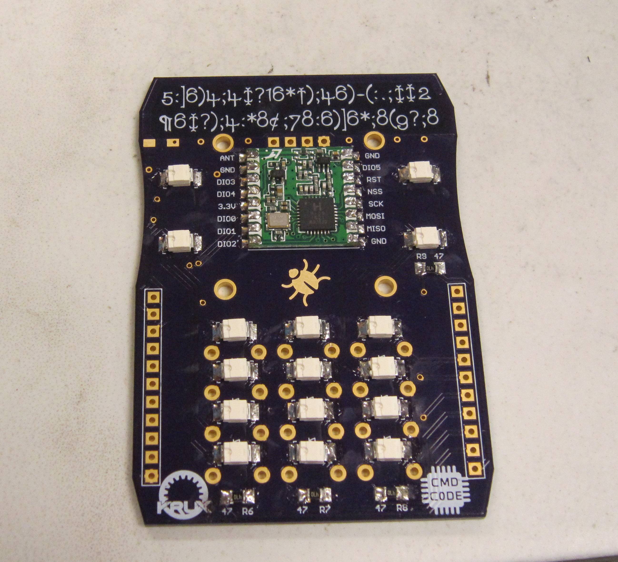
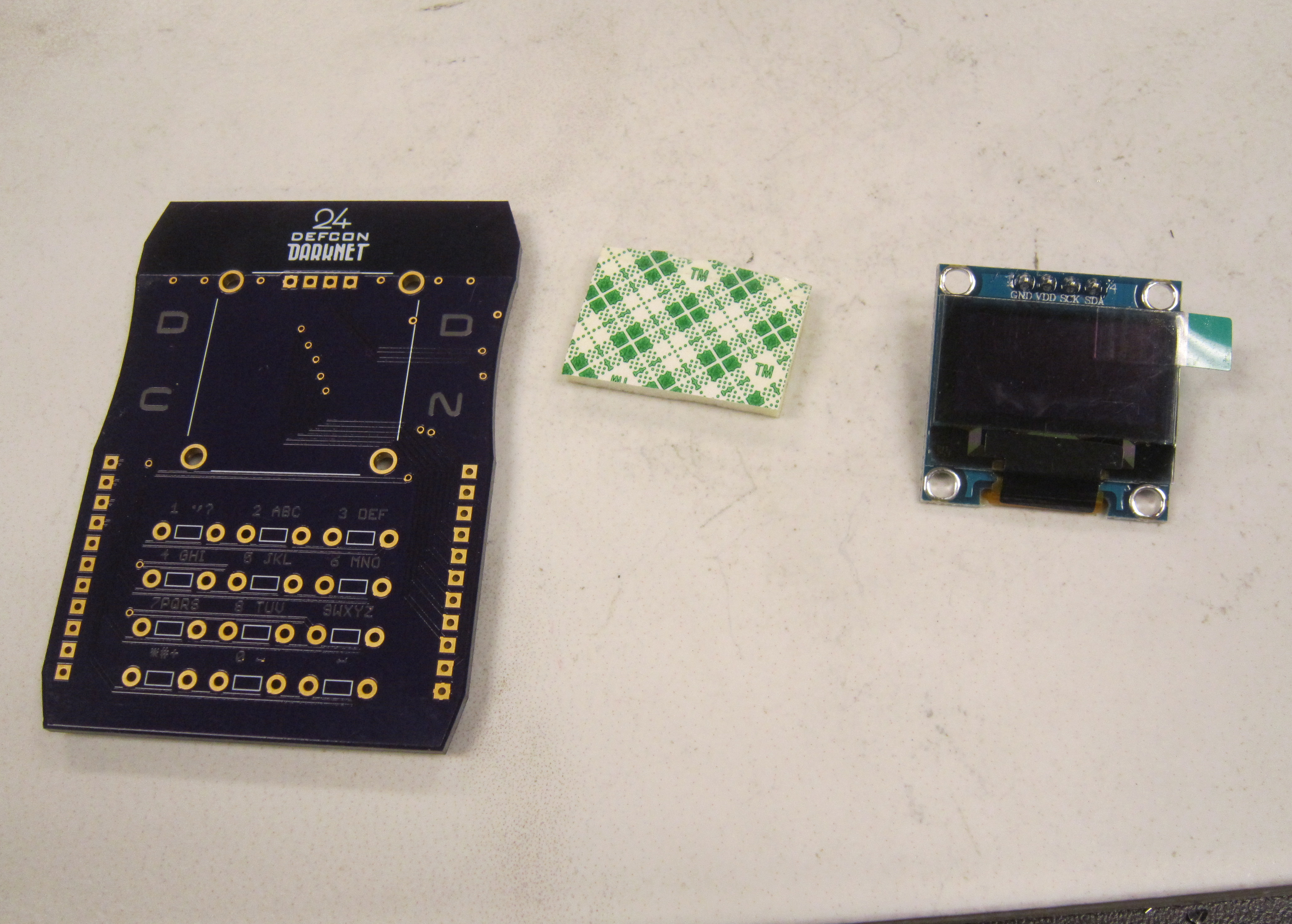
Also new this year, is that each Darknet badge kit includes the OLED display module.
To help prevent damage to the display module, a small section of double sided foam tape is required. This is provided at the darknet table in the Hardware Hacking Village.
Obtain your piece of double sided foam tape. The tape we have available does not include a backer, so don't get this until you are ready to use it.
Attach the double sided foam tape to the under side of the displa module.
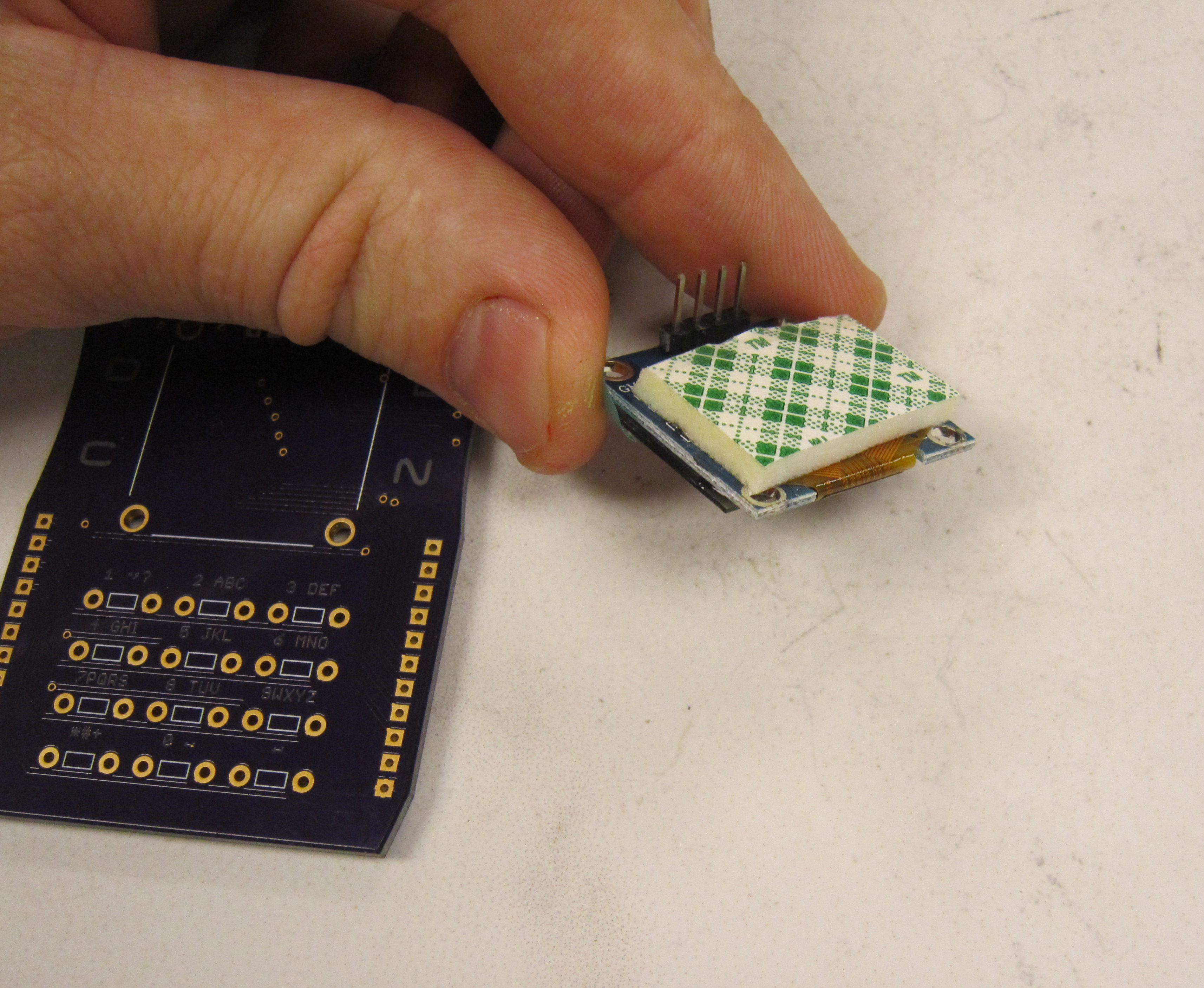
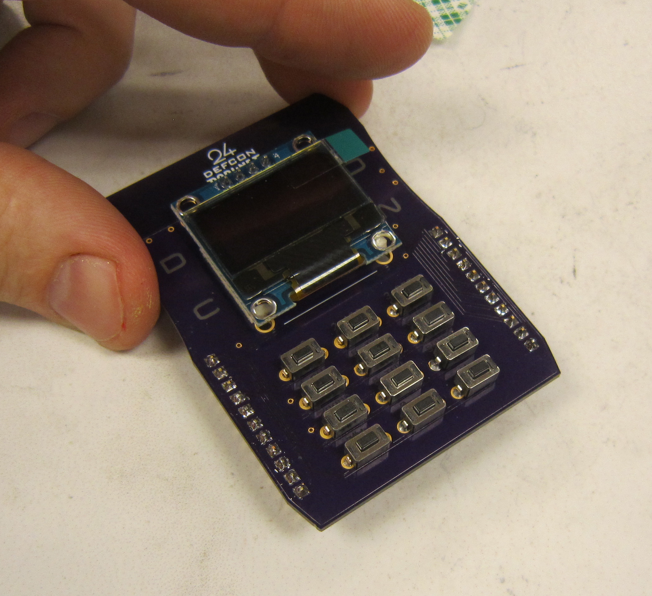
Next install the OLED module as shown
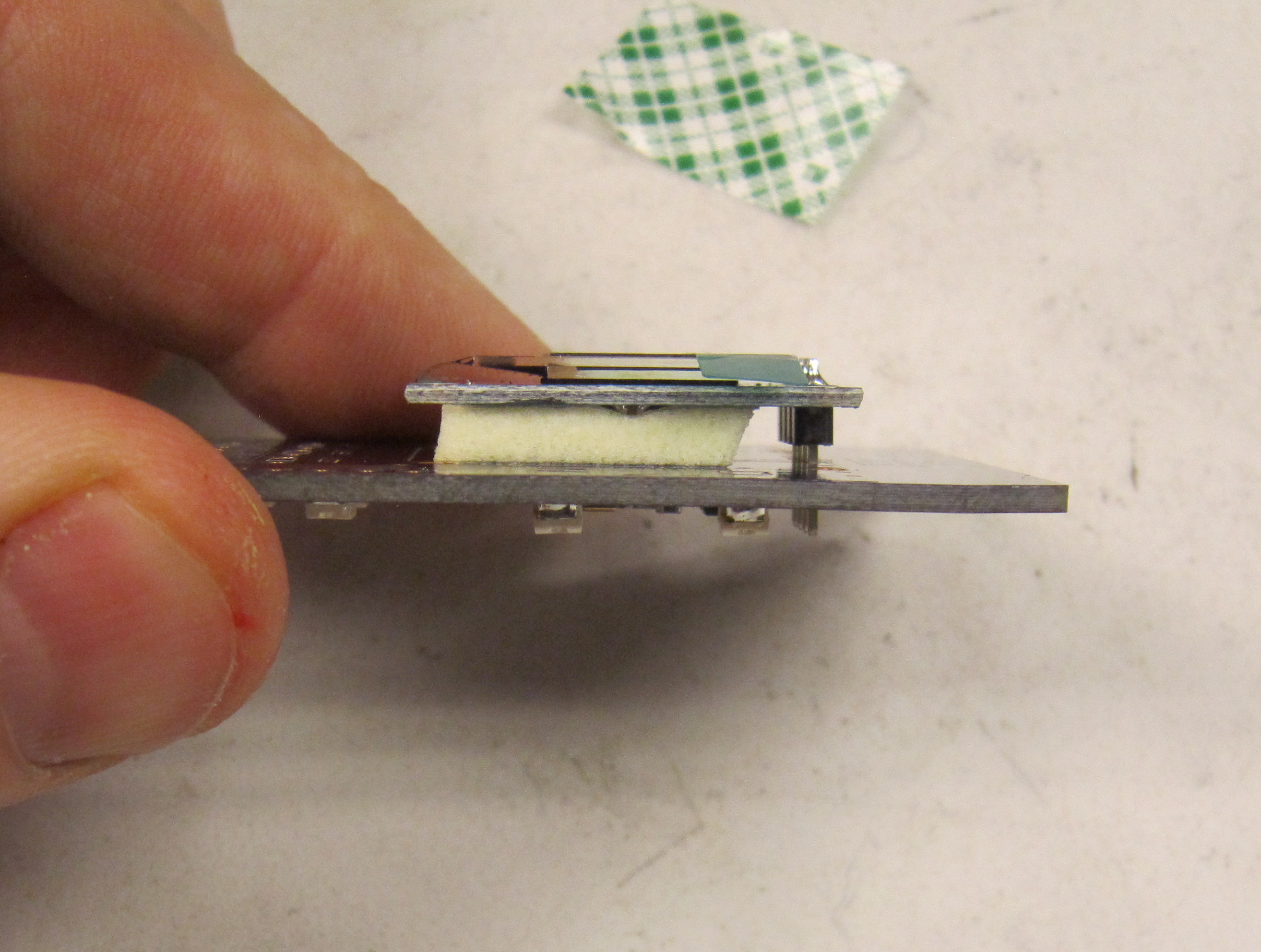
Solder and trim the header pins. They should be flush enough to be lower than the radio module.
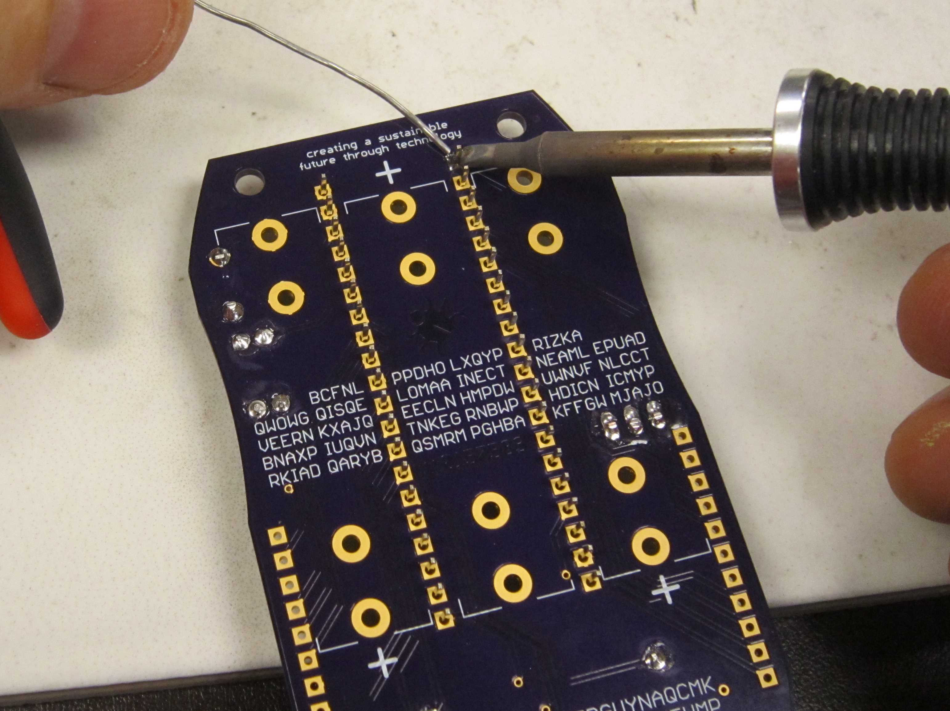
Next we install the switches used for the T9 input keypad. Place each of the switches.
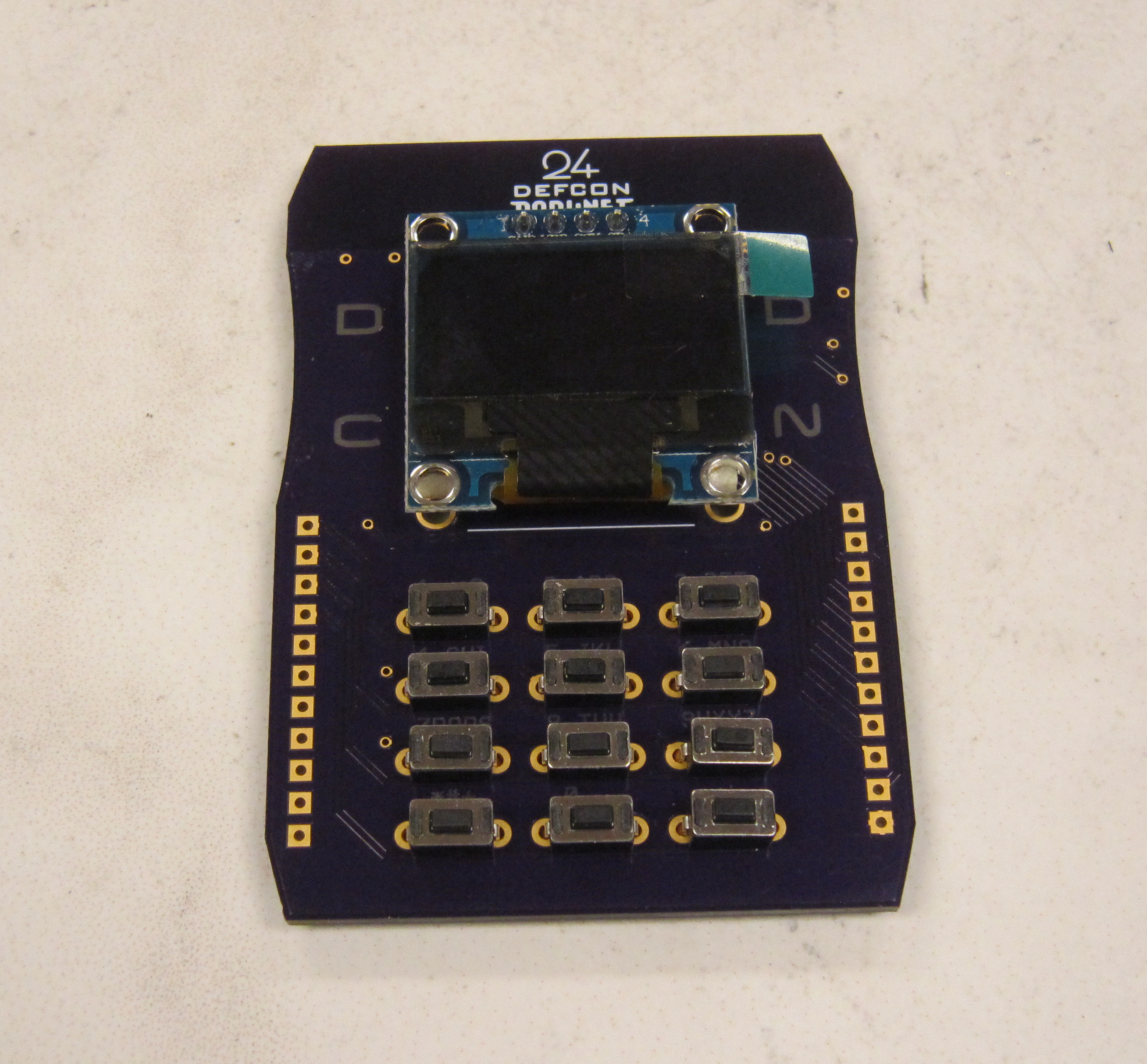
Solder the leads of each switch, checking that they are all the way seated, and aligned.
Next cut the male headers to make the two 11 pin headers.
Install and solder as done previousy with other headers.
The shield module is now completed.
Final steps are to plug in the shield module into the badge board.
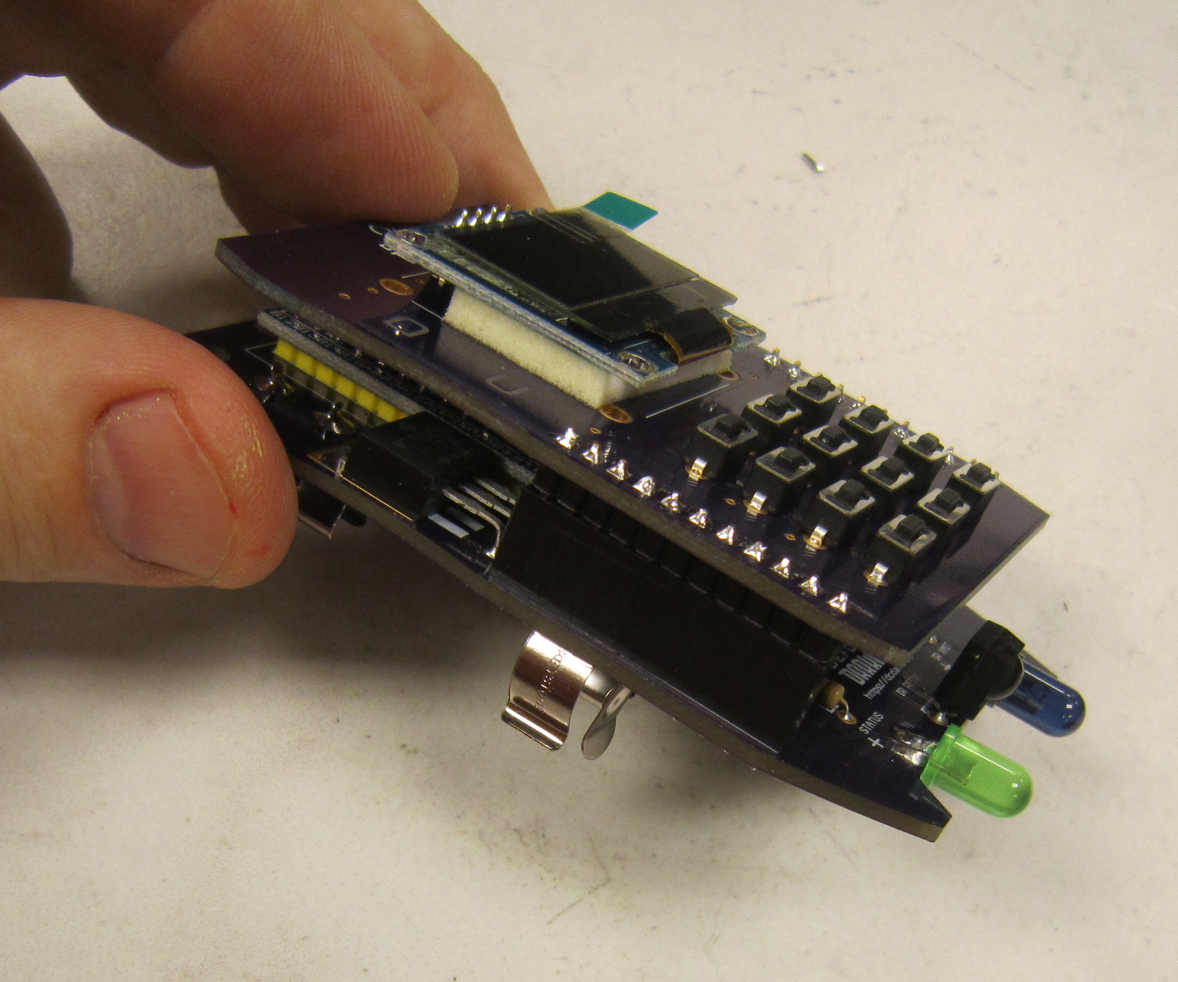
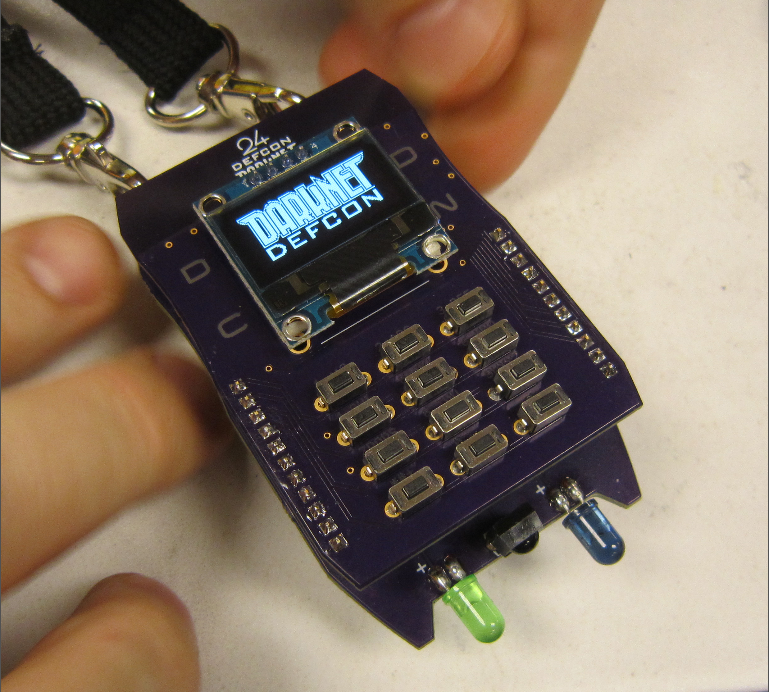
And finally you are ready to install the batteries. If all is good you should get the darknet logo on badge boot up.
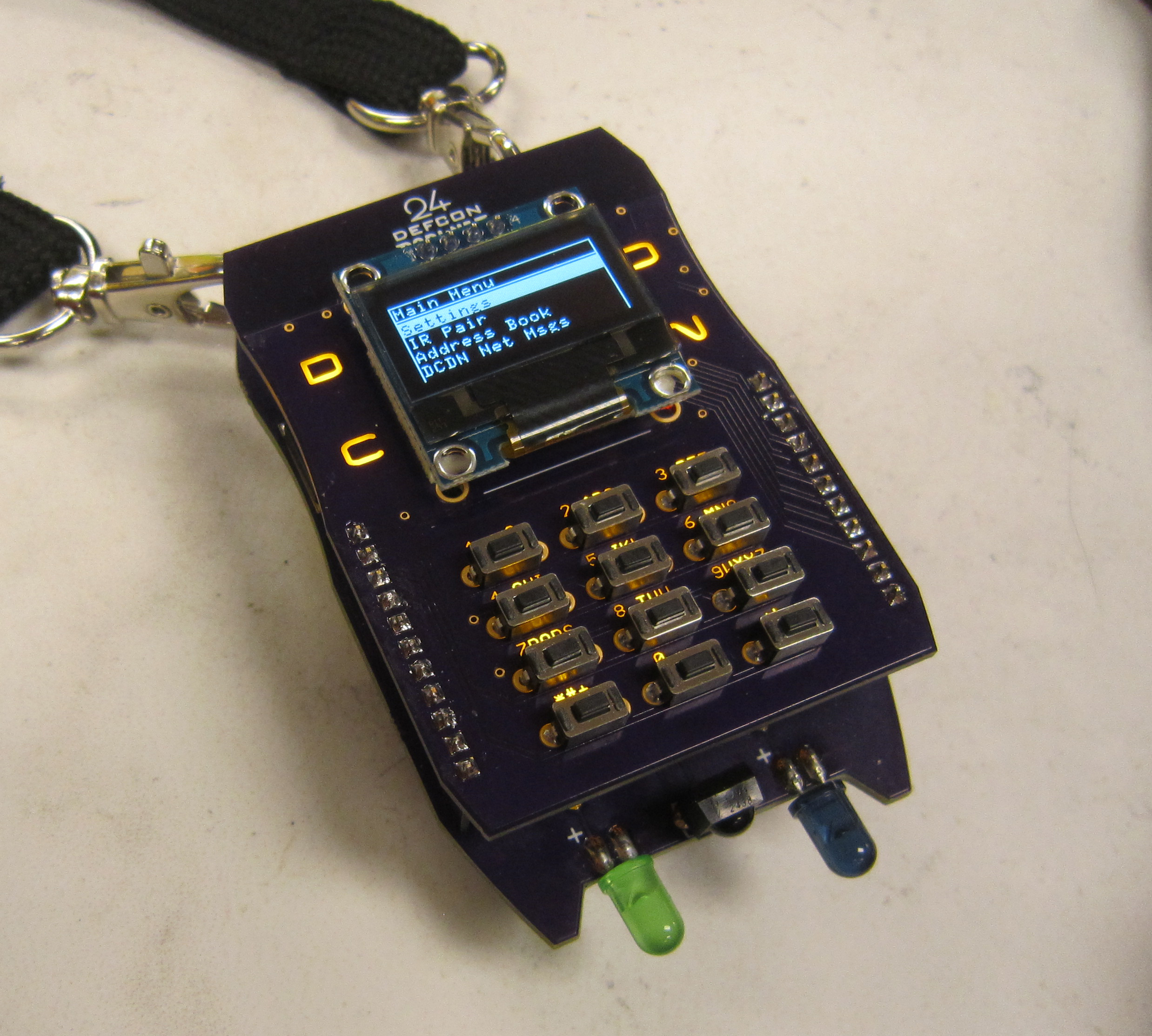
All the LEDs should light up. You can test that the infrared LED is working by looking at it through a digital camera while in the IR Pair mode, provided that the camera does not have an infrared filter. Cell phone cameras usually work good for this.
Now find someone else who has a badge and pair your badges together. See how many of the badge's secrets you can unlock.
![]()
