
These are the assembly instructions for the DefCon DarkNet 2015 Badge Display Kit.
The display kit helps extend the capability of your DarkNet Badge. It also gives you a great platform for further hacking your badge to do more awesome things.
The badge hardware was developed by Krux, and the badge firmware to support the display code was developed by CmdC0dez.
Avoid common mistakes, and read through this guide in it's entirety before beginning.
You will need the following tools to assemble this kit
- Temperature controlled soldering station
- Fine solder, 0.032" diameter or smaller
- De-soldering pump / de-soldering braid
- Flush cut wire cutters
- Needle nose pliers
- Safety glasses
- Optional: PCB vice
- Optional: Denatured alcohol to clean the board after soldering
When soldering, it is important to always follow safe work habits. Be mindful of yourself and others. The following documents address some of the safety concerns when soldering
- Soldering Safety
- Lead Soldering Safety Guidelines
- Lead-Free_Solder_Fumes_Increase_Need_for_Fume_Extraction
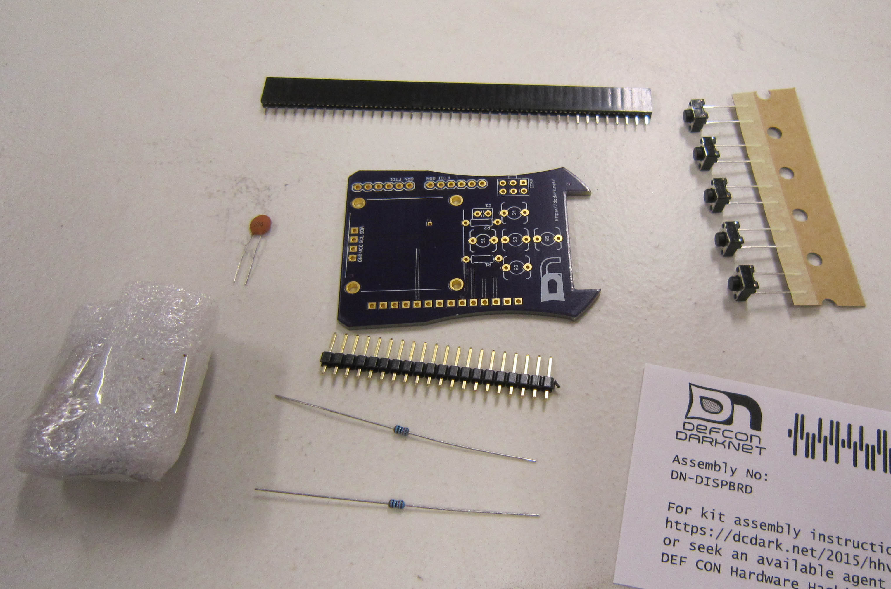
Before you get started, take a moment to ensure that all the components have been included with the kit.
Note: This is also a good time to turn on your soldering iron. For leaded solder, 320 degrees Celsius is a good working temperature.
- One Printed Circuit Board [in OSH Park purple]
- One OLED Display Module
- One Female Header
- One Male Header
- Five Tactile Switches SPDT
- Two 10K Ohm 1/8W 5% carbon film resistor [Brown Black Orange]
- One 0.1UF 50V Ceramic Disc Capacitors
Click on any of the images for a high-resolution version.
We'll utilize the same soldering techniques used when assembling the main badge.
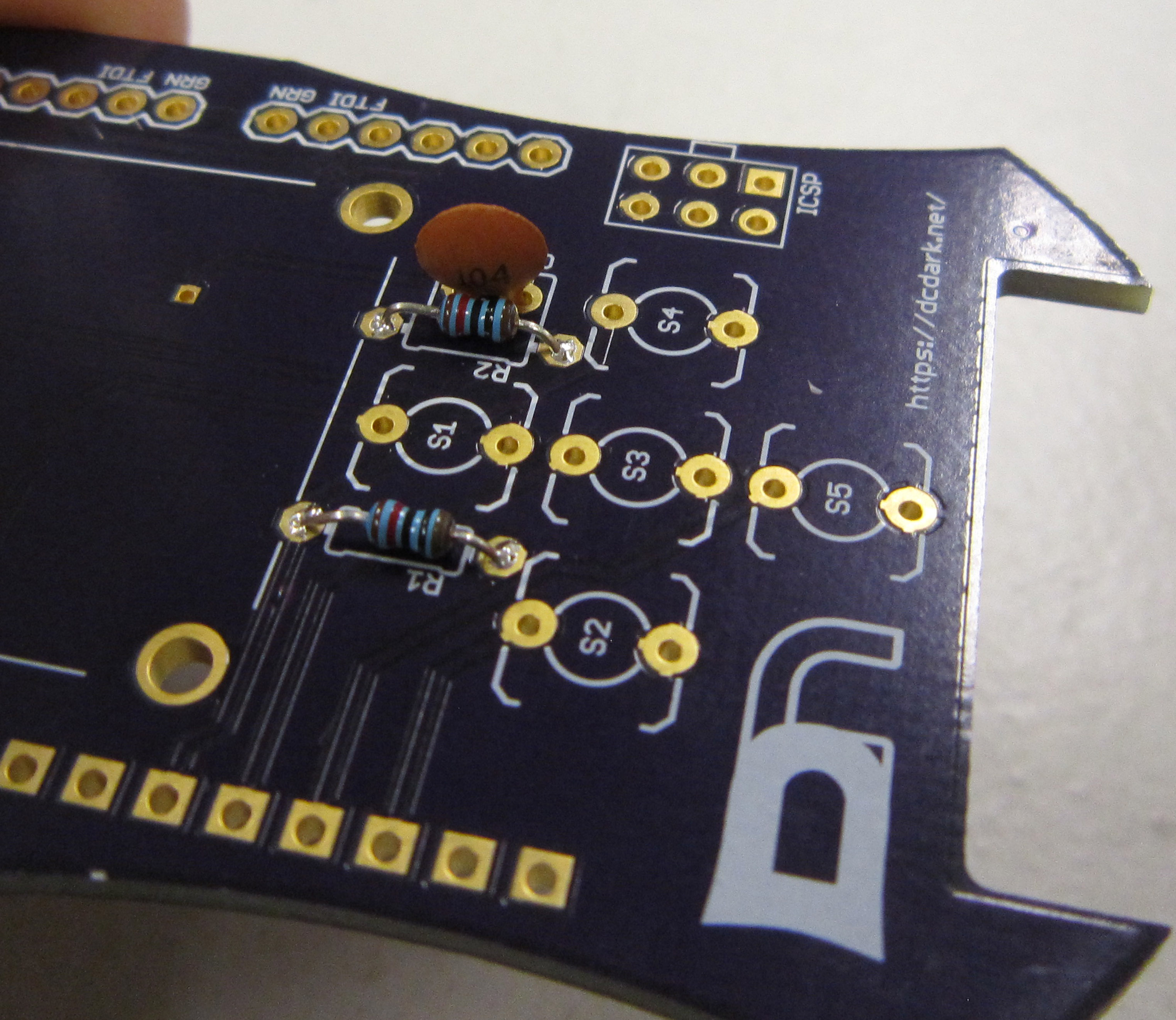
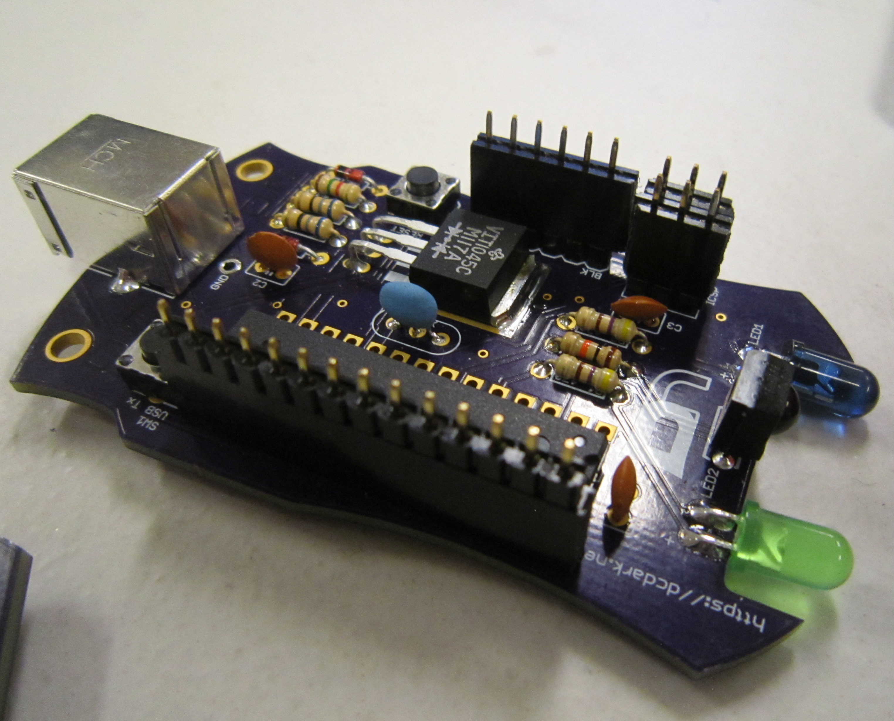
Start by soldering the 10K Ohm resistors R1, and R2. Resistors do not have a polarity and can be installed in either direction. Start by bending the leads as shown, so they may be inserted into PCB.
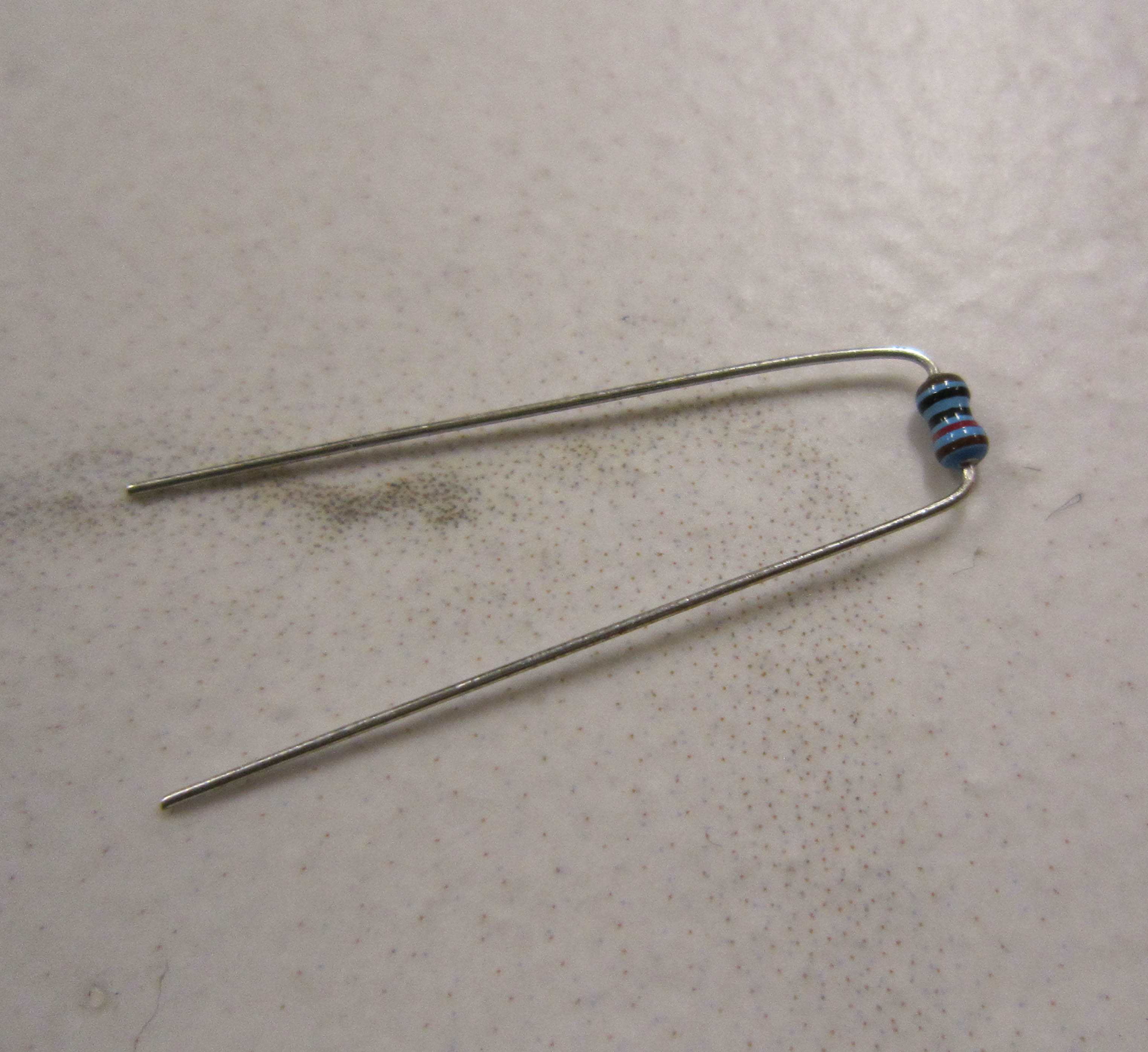
Populate the components, so they are on the top side of the board. The parts should lay flush with the PCB.
To aid in soldering, and to help keep the components in place, the leads may be splayed at a slight angle to hold the parts in place. Double check that the parts are still flush with the PCB before soldering.
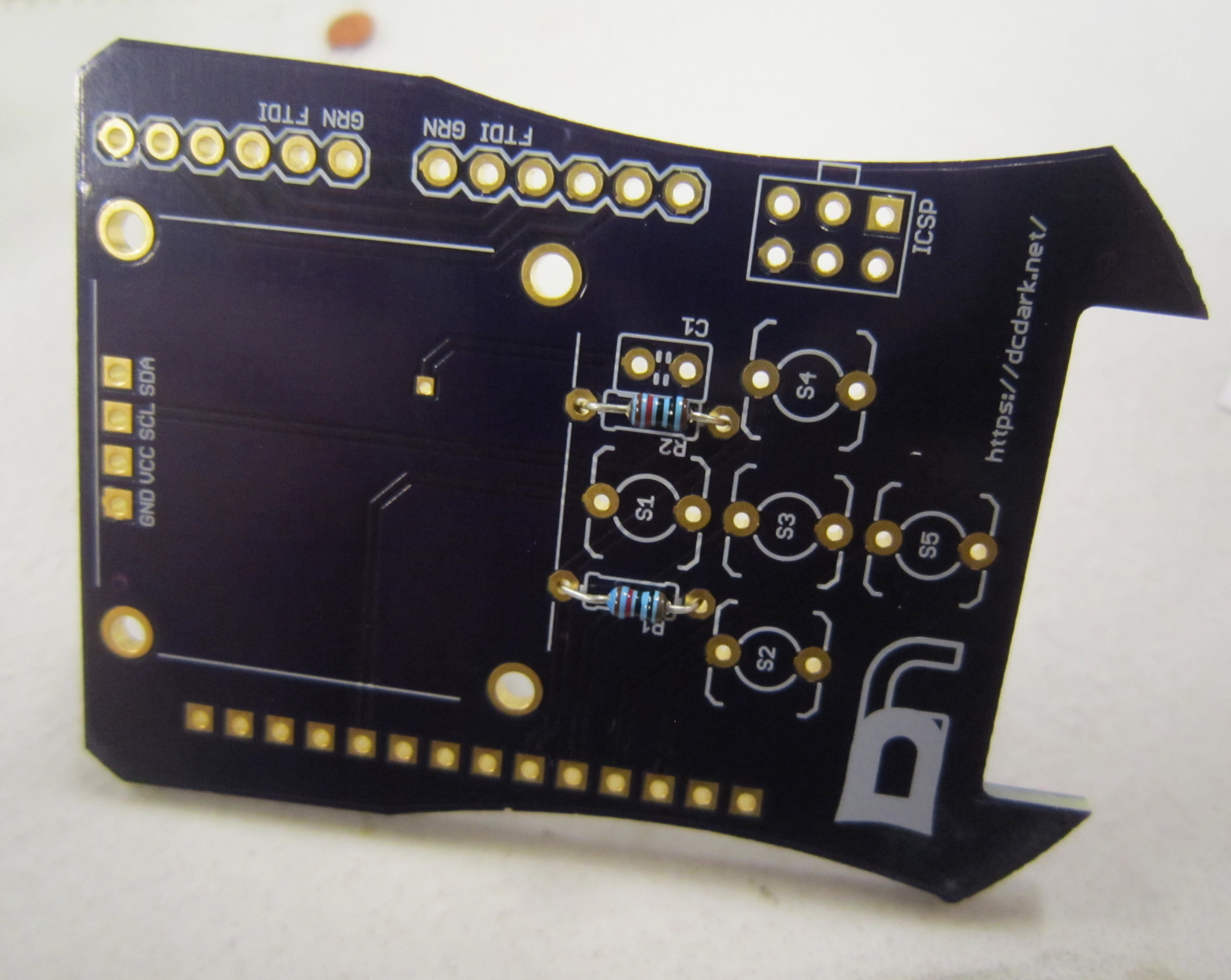
Next trim the resistor leads close to the board. This should be where the component lead meets the solder, as shown here.
Next we will solder in the capacitor C1. Capacitors can be polarized or non-polarized. The capacitors included in this kit are non-polarized and may be installed in either direction.
Install the capacitors as shown.
Solder and trim the leads as you did with the other components.
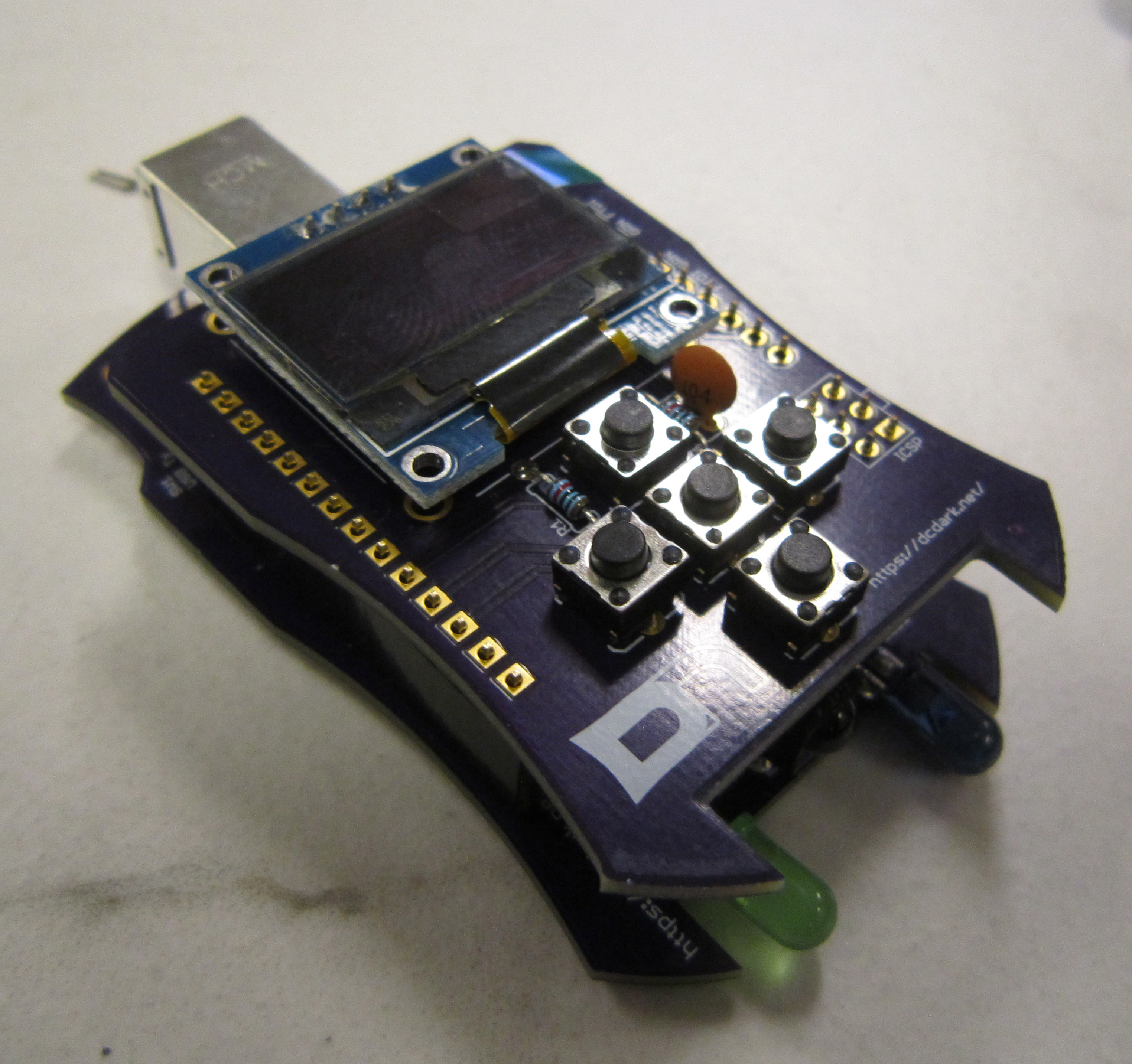
Next install the five microswitches, SW1, SW2, SW3, SW4, and SW5. These components are not polarized, and may be installed in either direction.
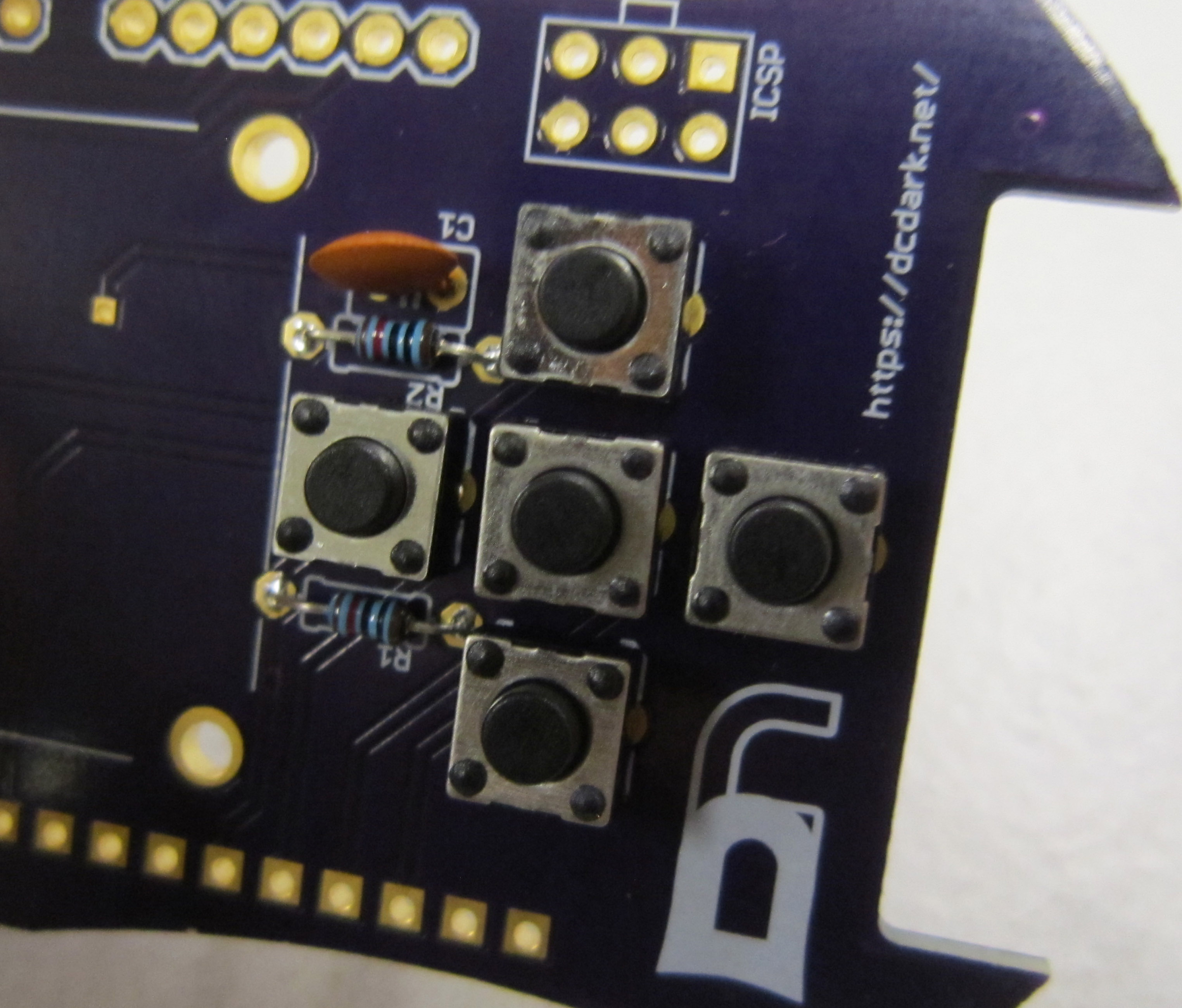
Solder and trim the leads.
Note: Though the instructions say to put the display module on next. There was a mistake I didn't catch on the boards, so we've had to add installing one bodge wire to make the right button on the display board functional. To make that step easier, you can opt to wait till the end to put the display board on. However as many will just assembly the display board without looking at the instructions, I'll show how to add in the bodge wire after the fact in a later step.
Install the display module as shown. The included four pin header will make the display sit just slightly away from the main PCB.
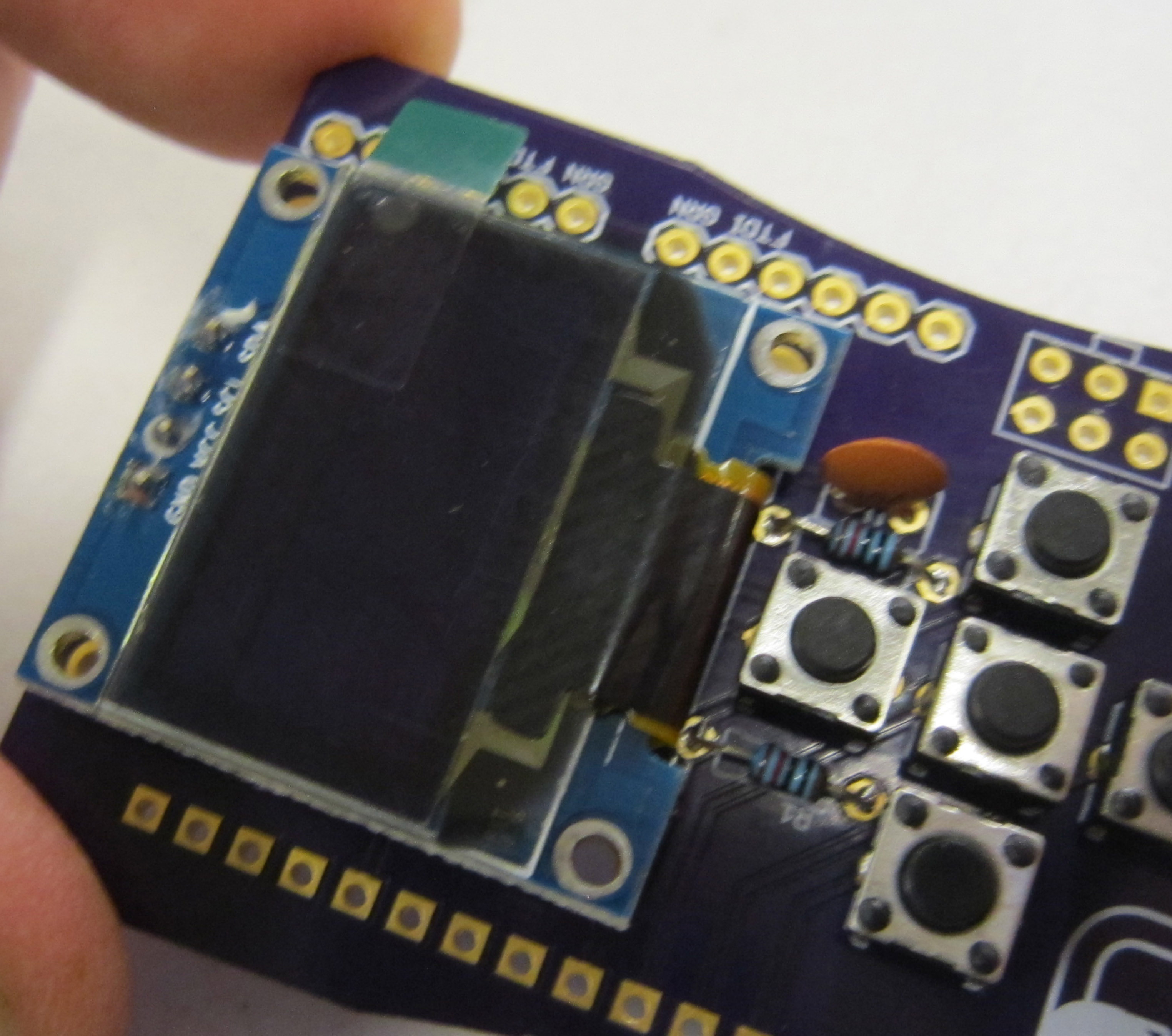
There is no need to trim the leads of the display board once installed.
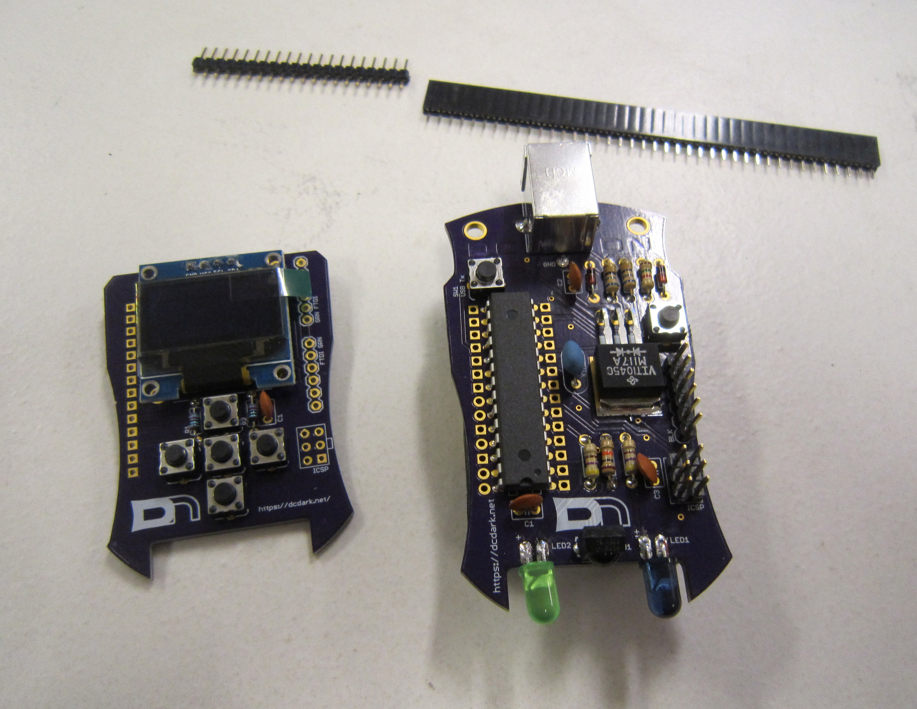
Included are some male and female headers.
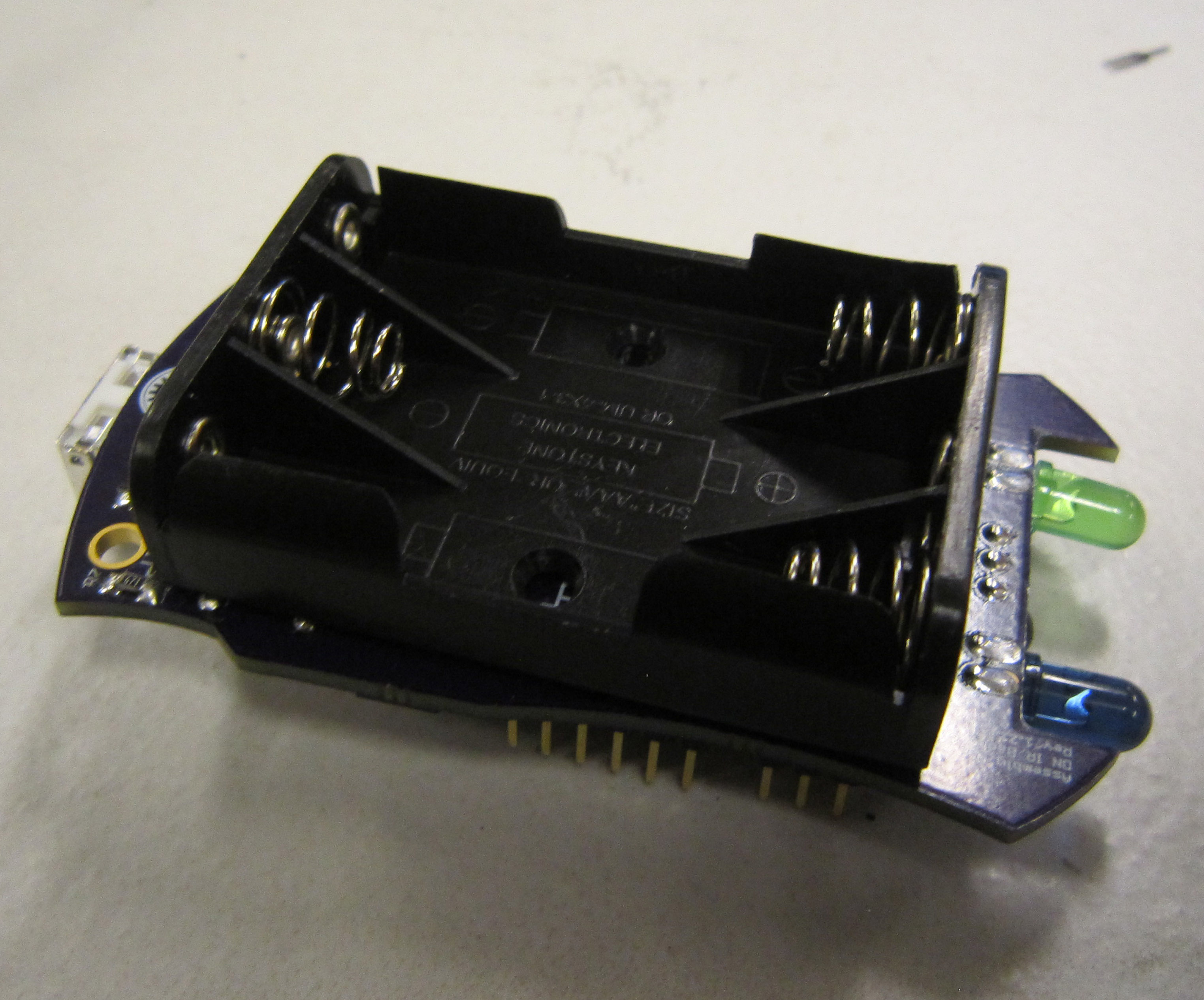
Before we begin, we first have to remove the battery holder off the main badge. Start by removing the batteries.
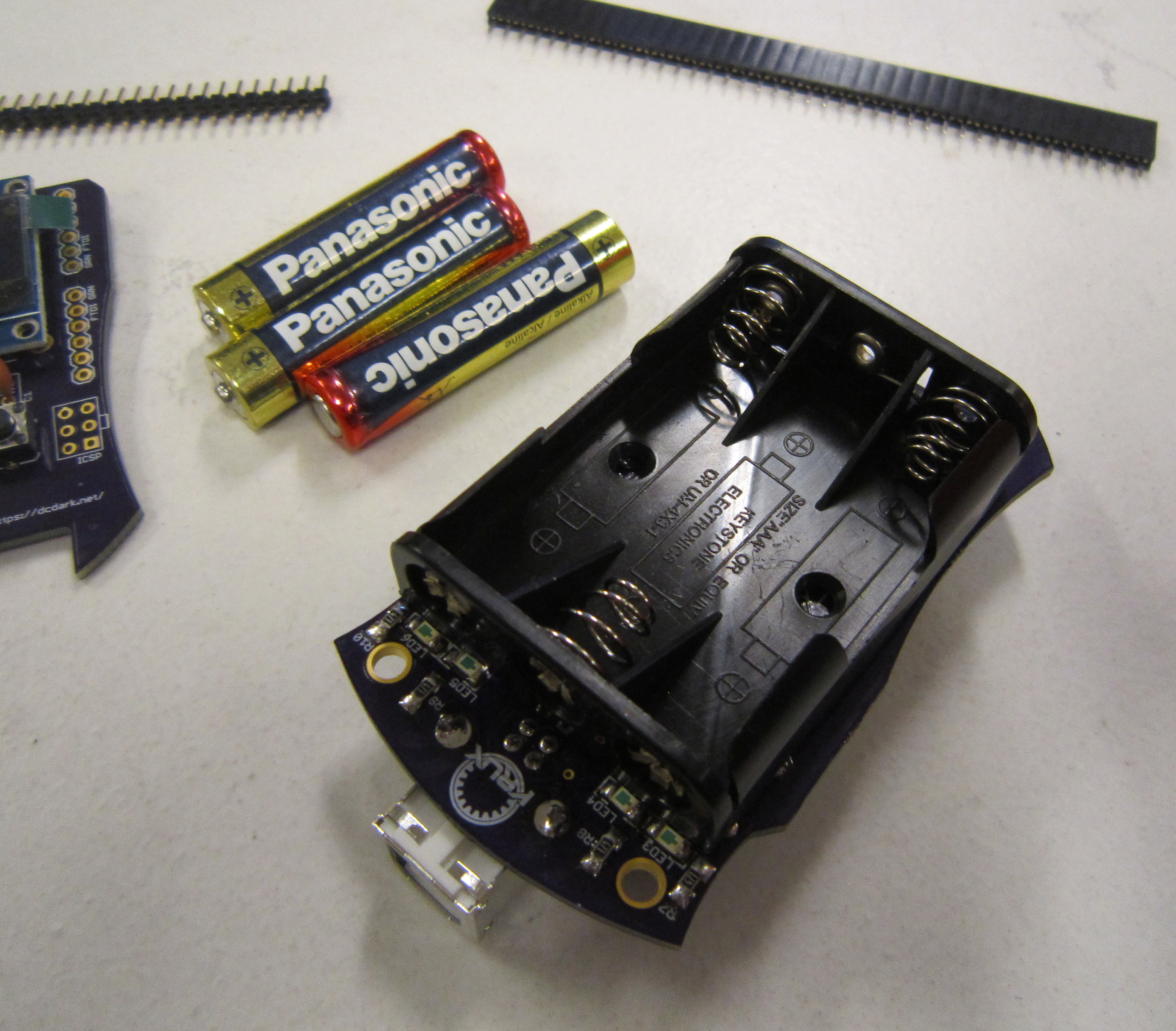
Next desolder the two leads for the battery holder using a solder sucker or de-soldering braid.
If you are having trouble desoldering, you can gradually work the battery holder loose by heating up one pin, and pulling that pin loose, then doing the same on the second pin. Switch back and forth between the two pins until the battery holder is free. Then clean the solder pads with solder braid.
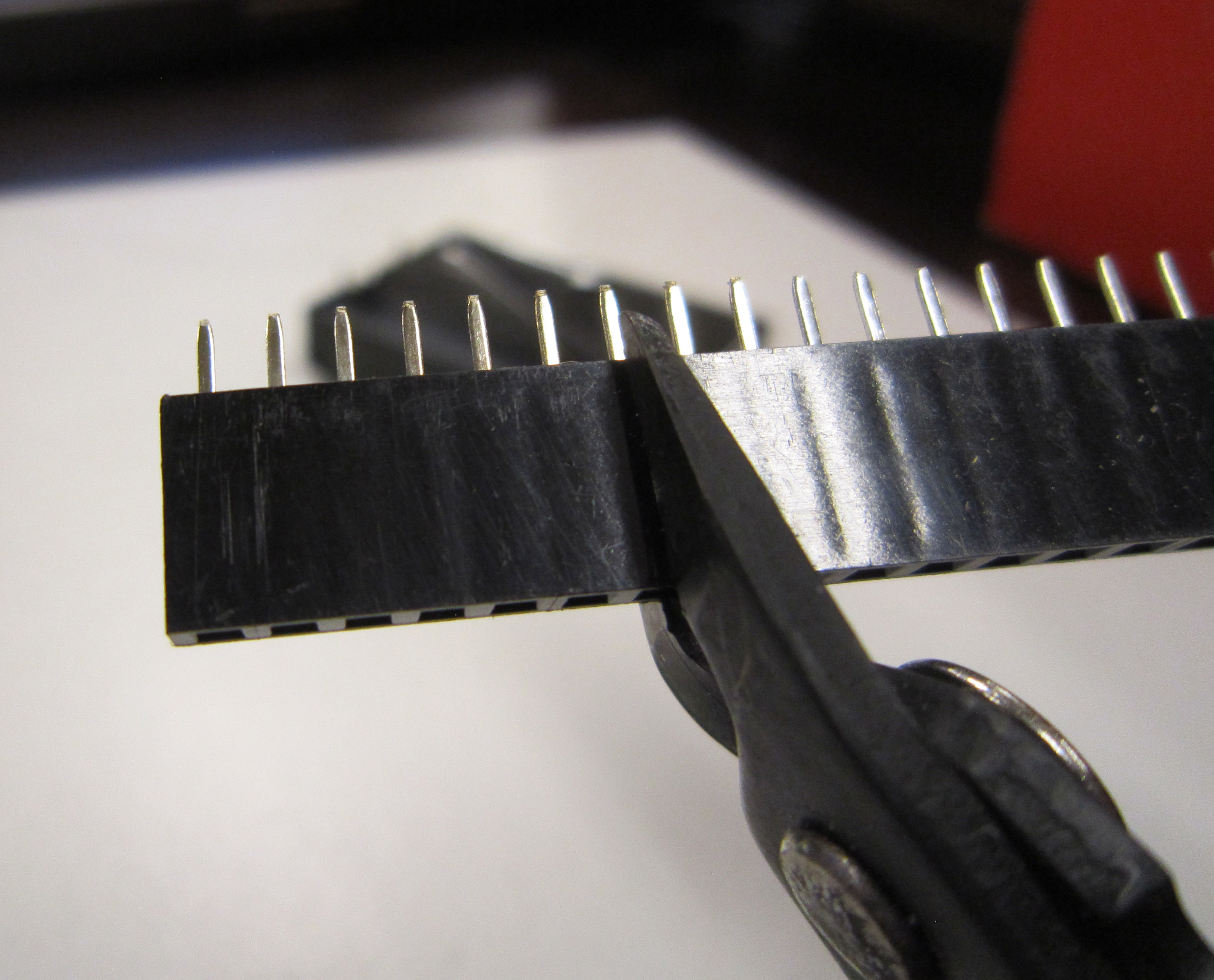
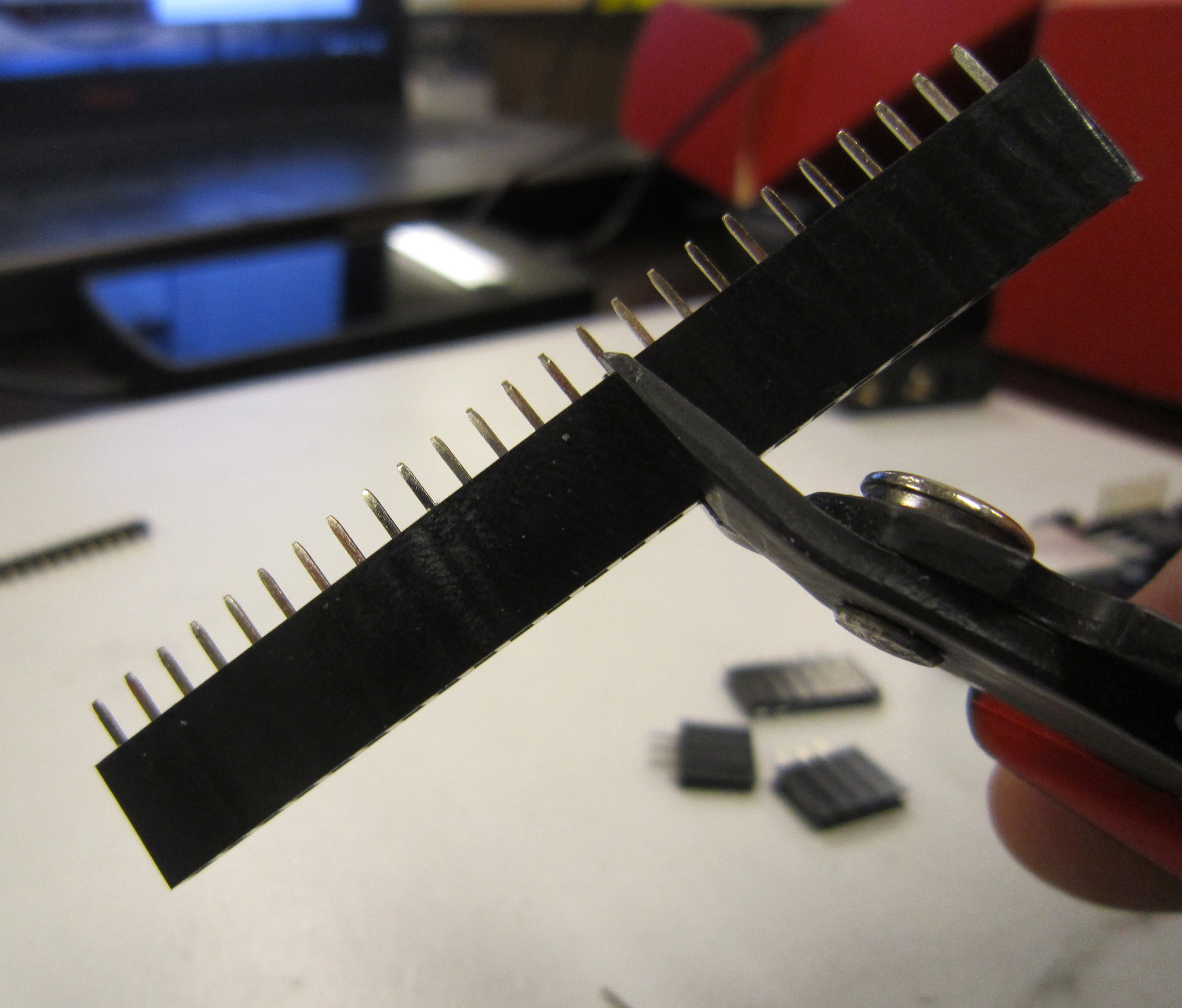
Next we need to cut our female headers. Female headers are not break away like the male headers, so there is a loss of one pin for each cut.
Start by creating a 6-pin header by cutting on the 7th pin from the end.
Next create two 3-pin headers by cutting on the 4th pin from the end.
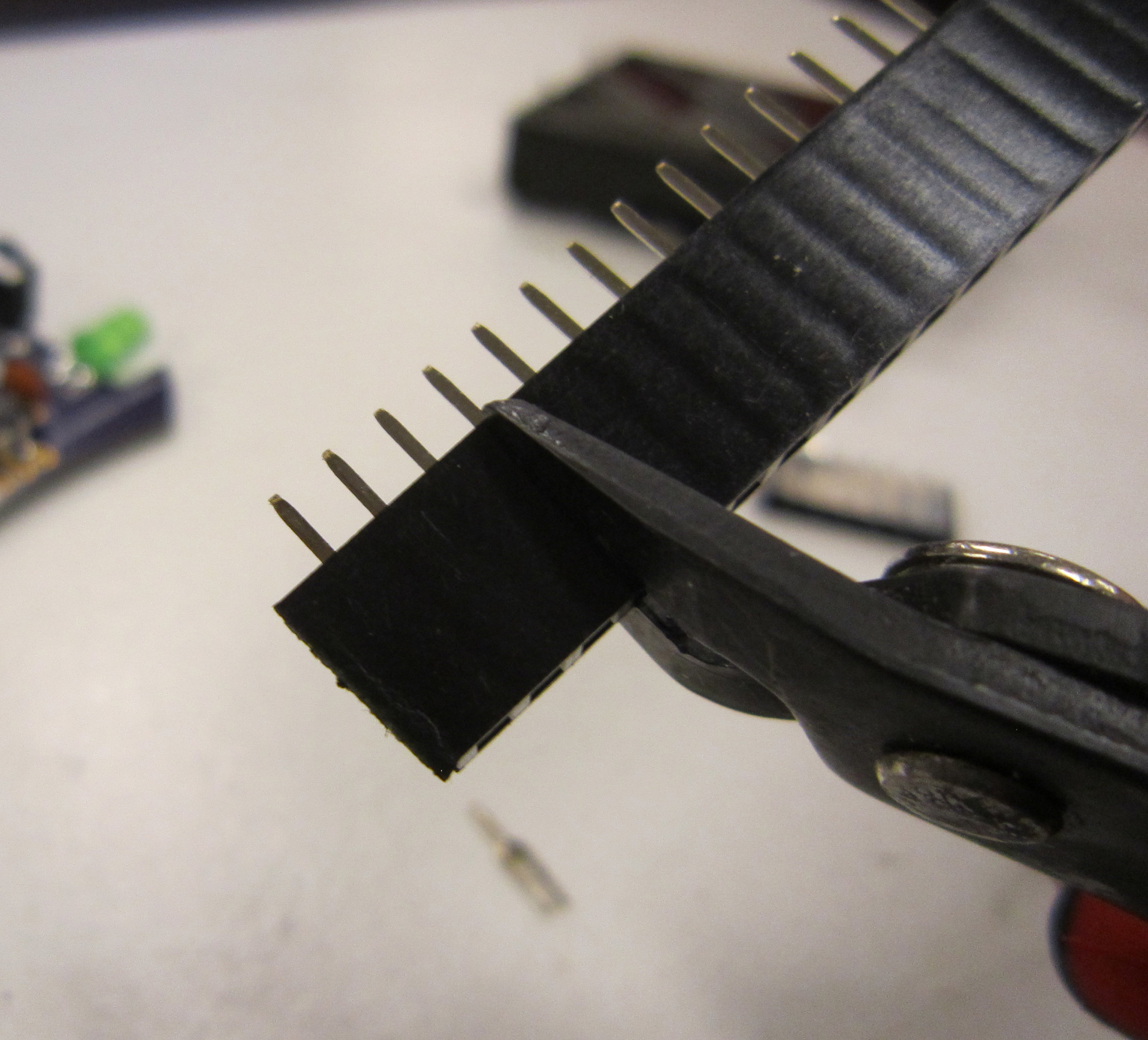
Finally we need a 14-pin header, so cut at the 15th pin from the end.
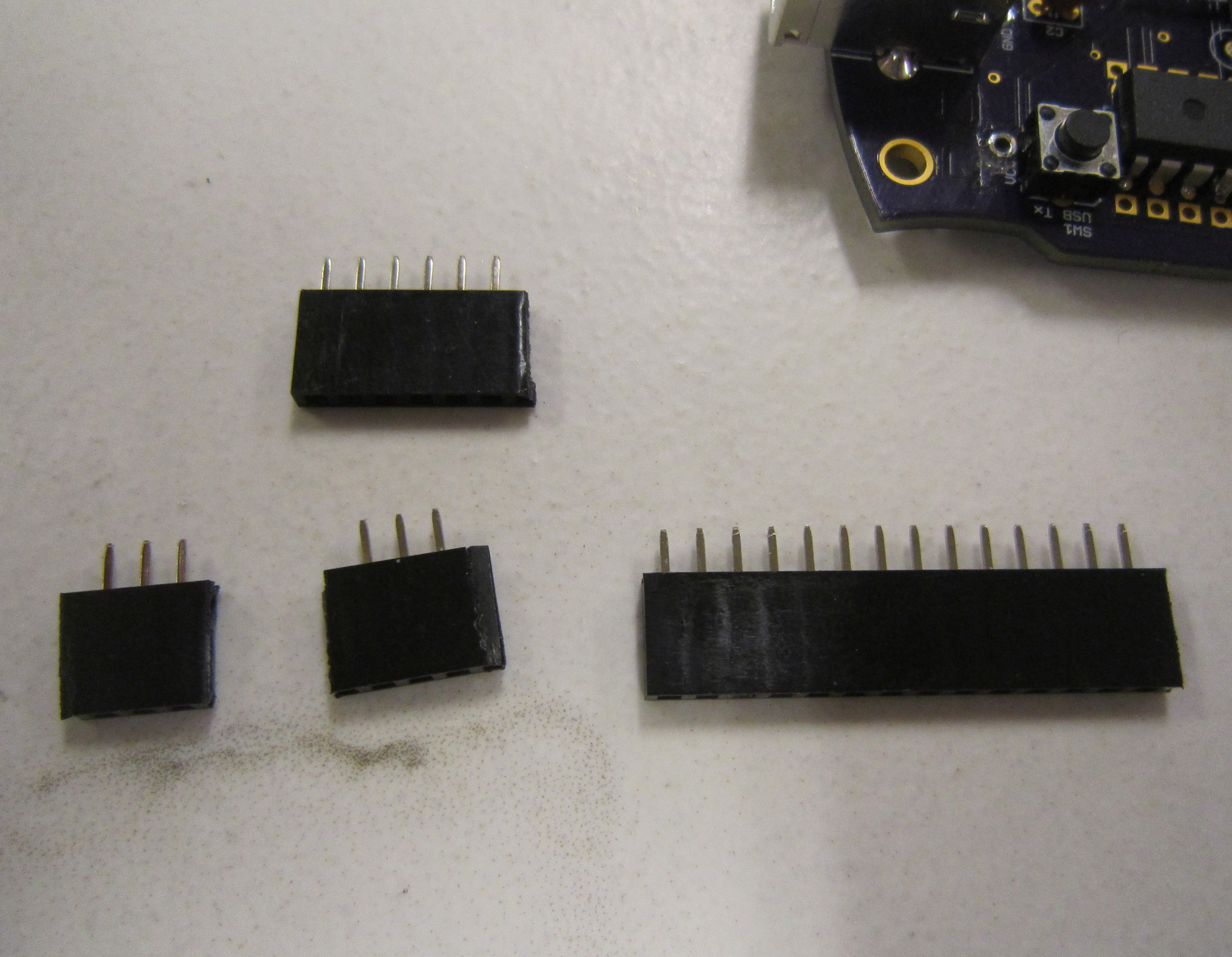
When finished you should have the following headers.
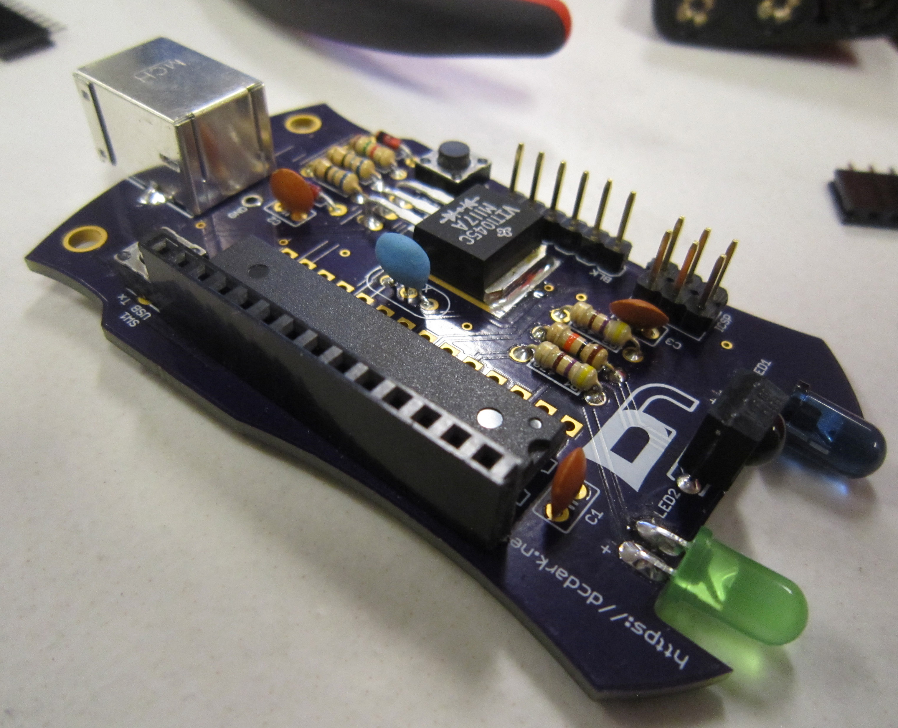
Install and solder the 14-pin header on your main badge as shown.
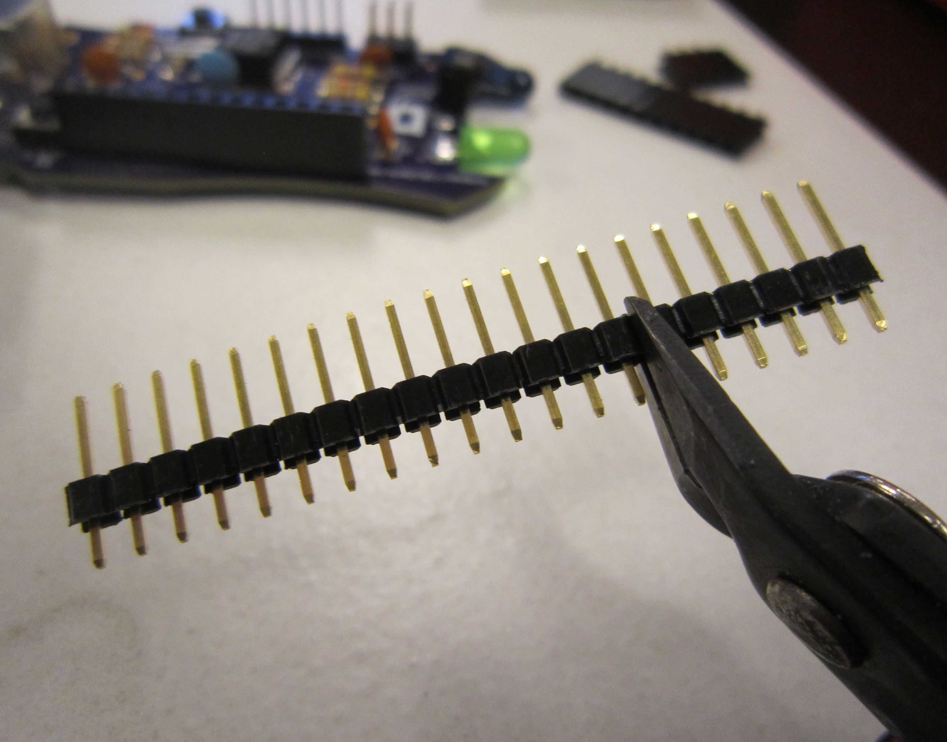
Next we need to cut the male header to create a 14-pin header and 6-pin header.
Now install the headers on the main board. This will make soldering to the headers to the display board easier.
Add the display board as shown, and then solder in place.
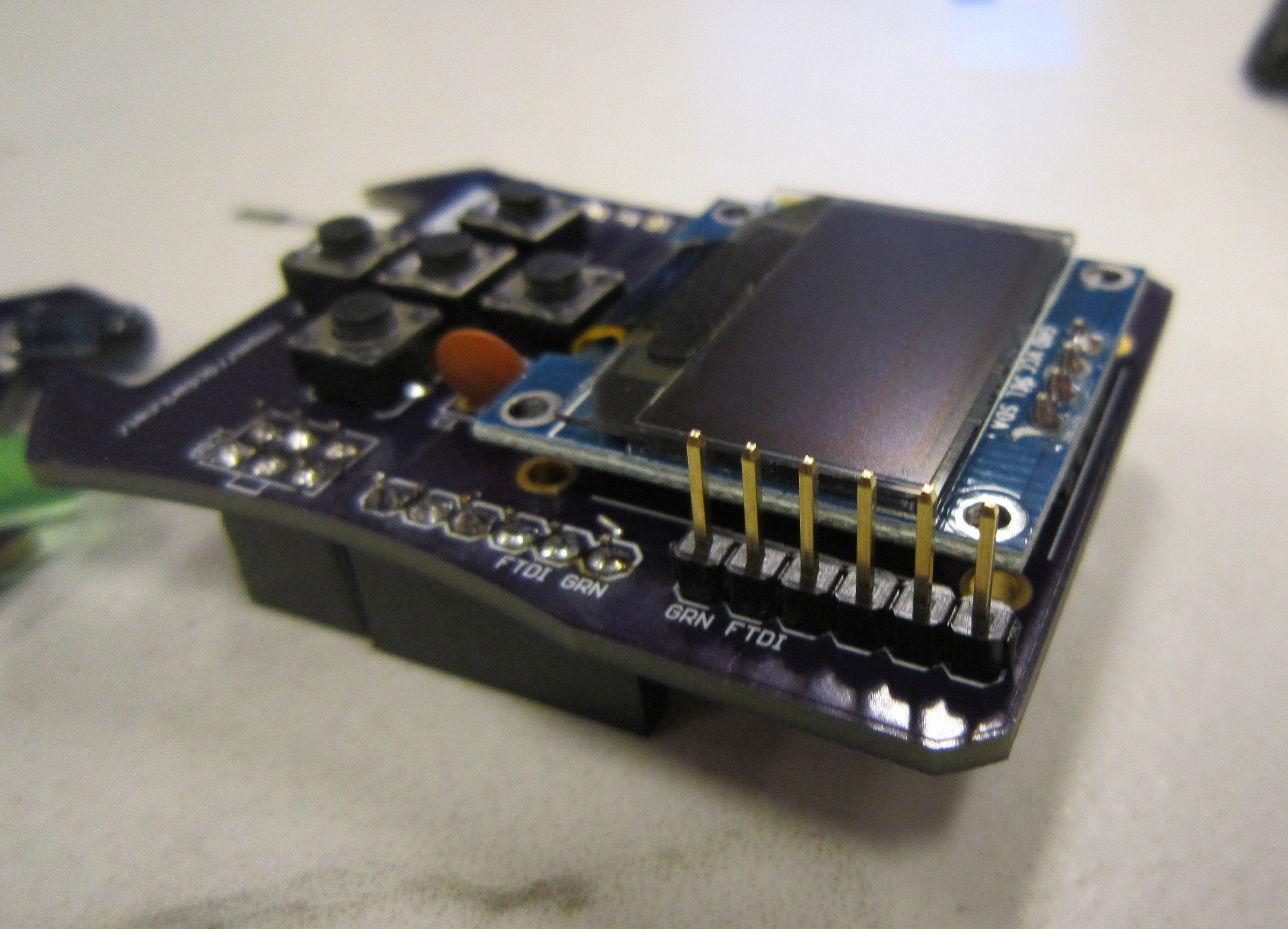
Next remove the display board from the badge, and add the six pin FTDI header, and solder in place.
Note: GRN indicates the green wire on a standard FTDI cable.
Now we can re-attach the battery holder to the main badge.
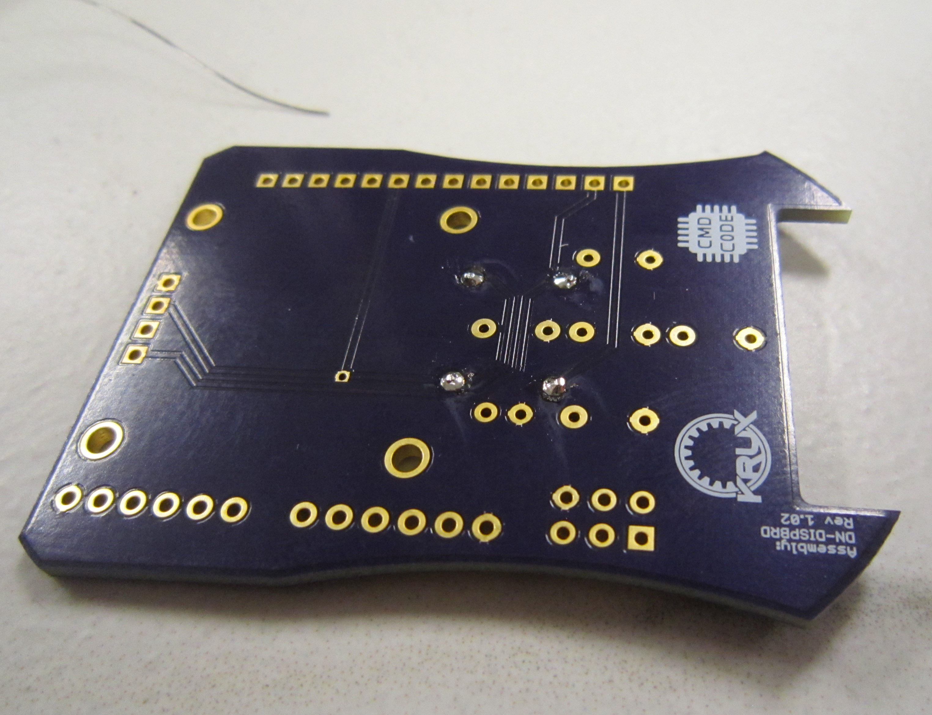
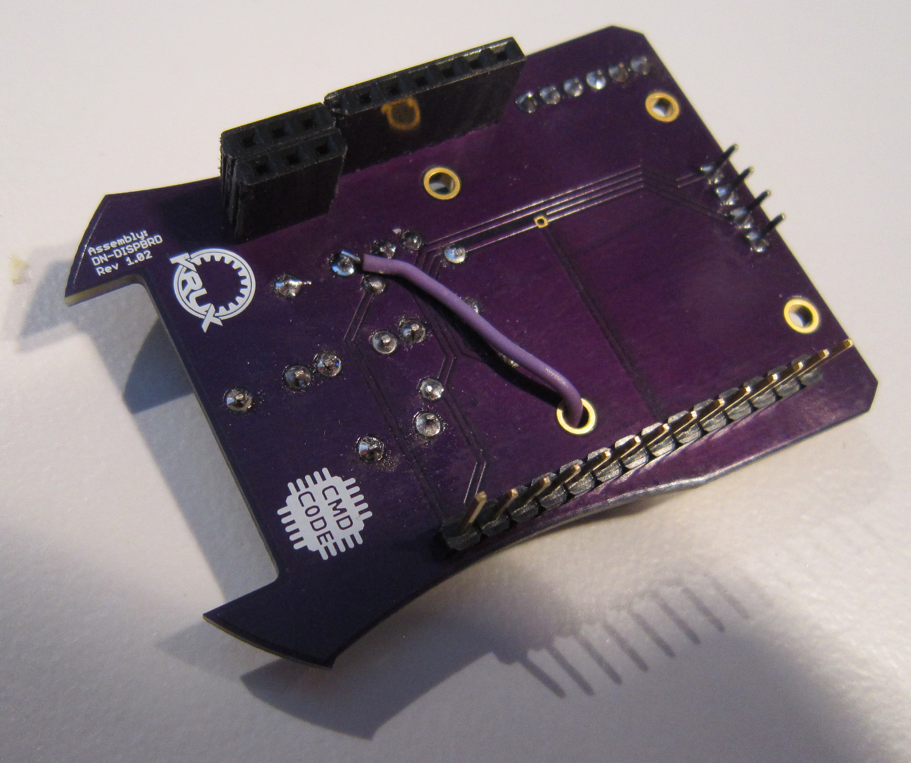
As I indicated earlier in the instructions, we took this opportunity to teach everyone how to install a bodge wire, and totally did not mess up the board by running the trace for the right button across a power via. Ok, well maybe there was a slight screw up. It's an easy fix however.
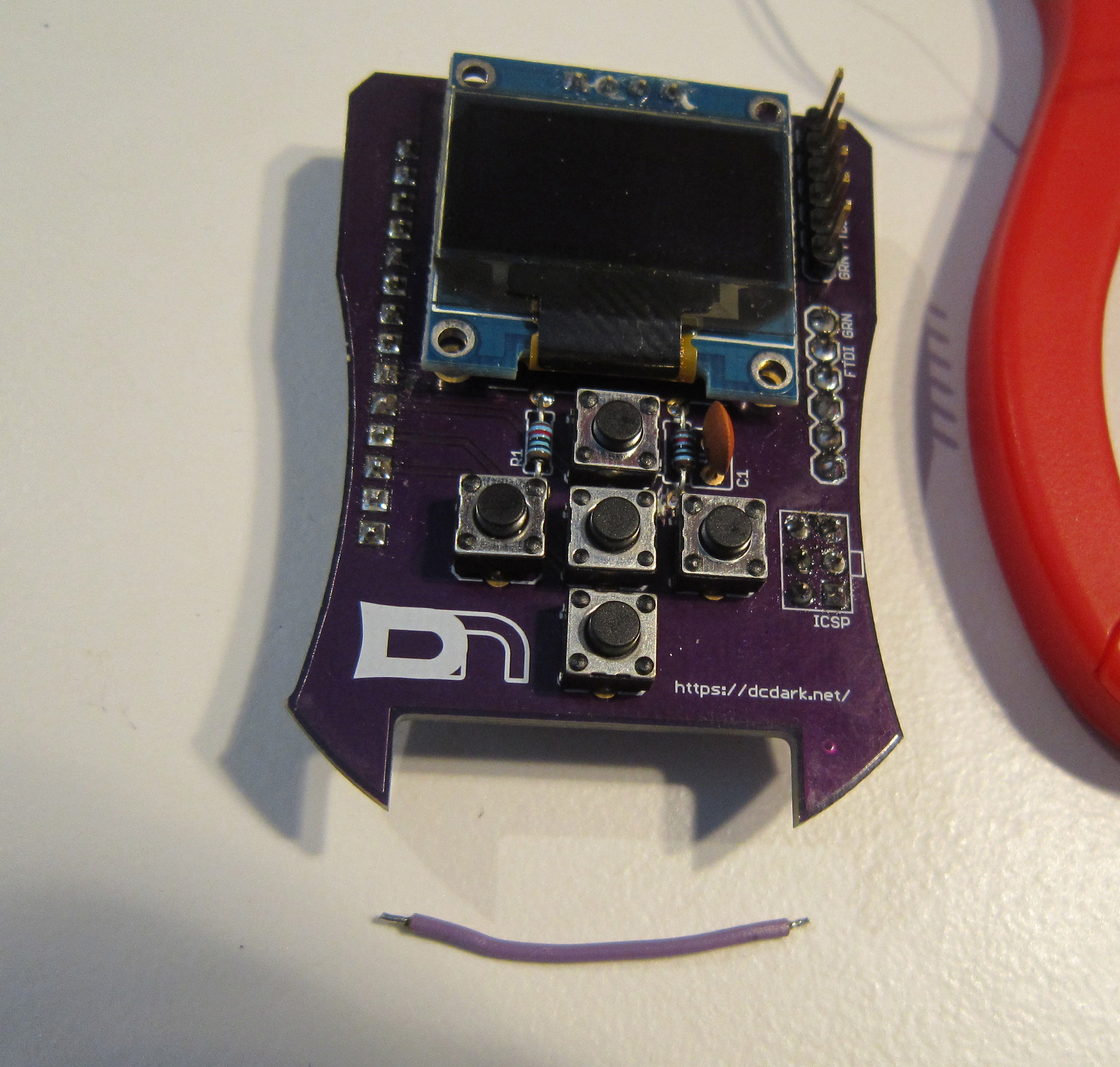
We took the opportunity to pre-cut the traces which needed to be severed, so all that will be required is to add a short segment of wire between the pin of S4 nearest C1, and pin 23 of the microcontroller, the 6th pin up from the DN logo.
Start by cutting a segment of wire, just a little longer than the distance between the two points on the display badge. Strip off about 1.5 to 2mm of the insulation. on each end
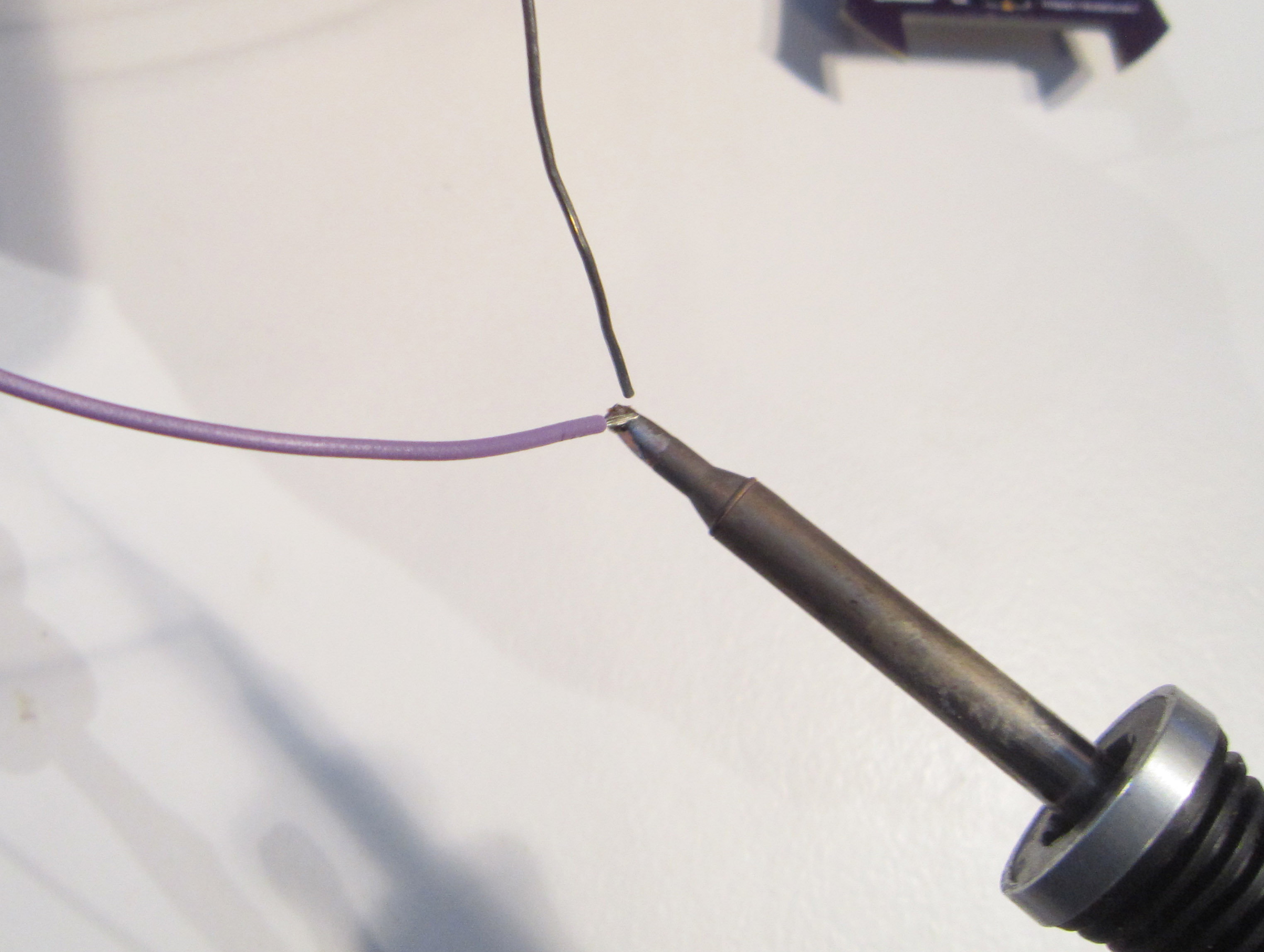
Next tin the leads of both ends of the wire. Do this by getting the wire hot with the soldering iron, and then dabbing just a little solder to the wire itself. You should see the solder wick into the strands of wire, and there should not be too much solder. It's just enough to coat the copper to aid in soldering.
Now on the 6th pin up from the DN logo, solder one end of the wire. If the wire is tinned and there is a sufficient amount of solder on the header pin, you will not need to add any additional solder.
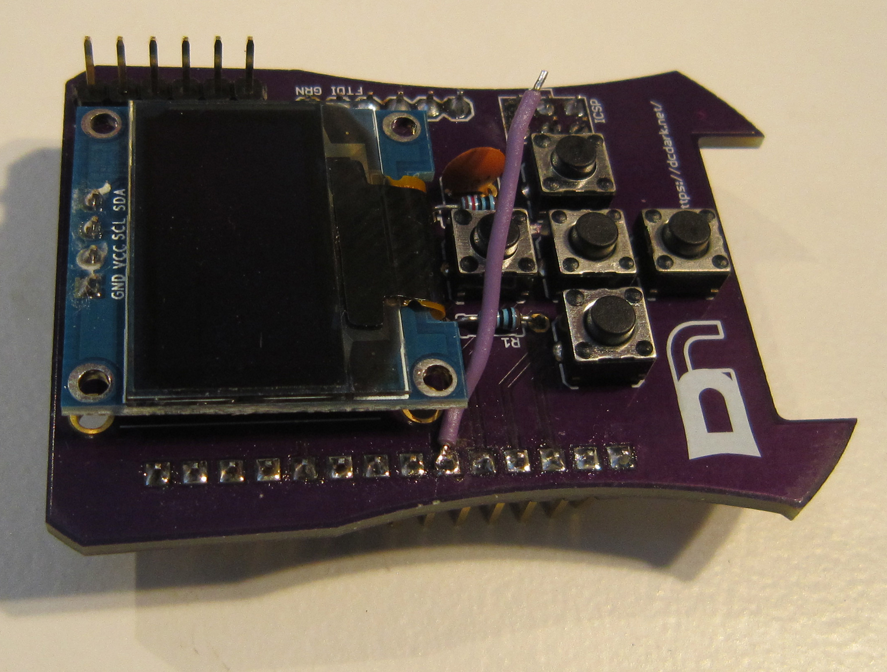
Next feed the wire through to the under side of the board using the near by hole.
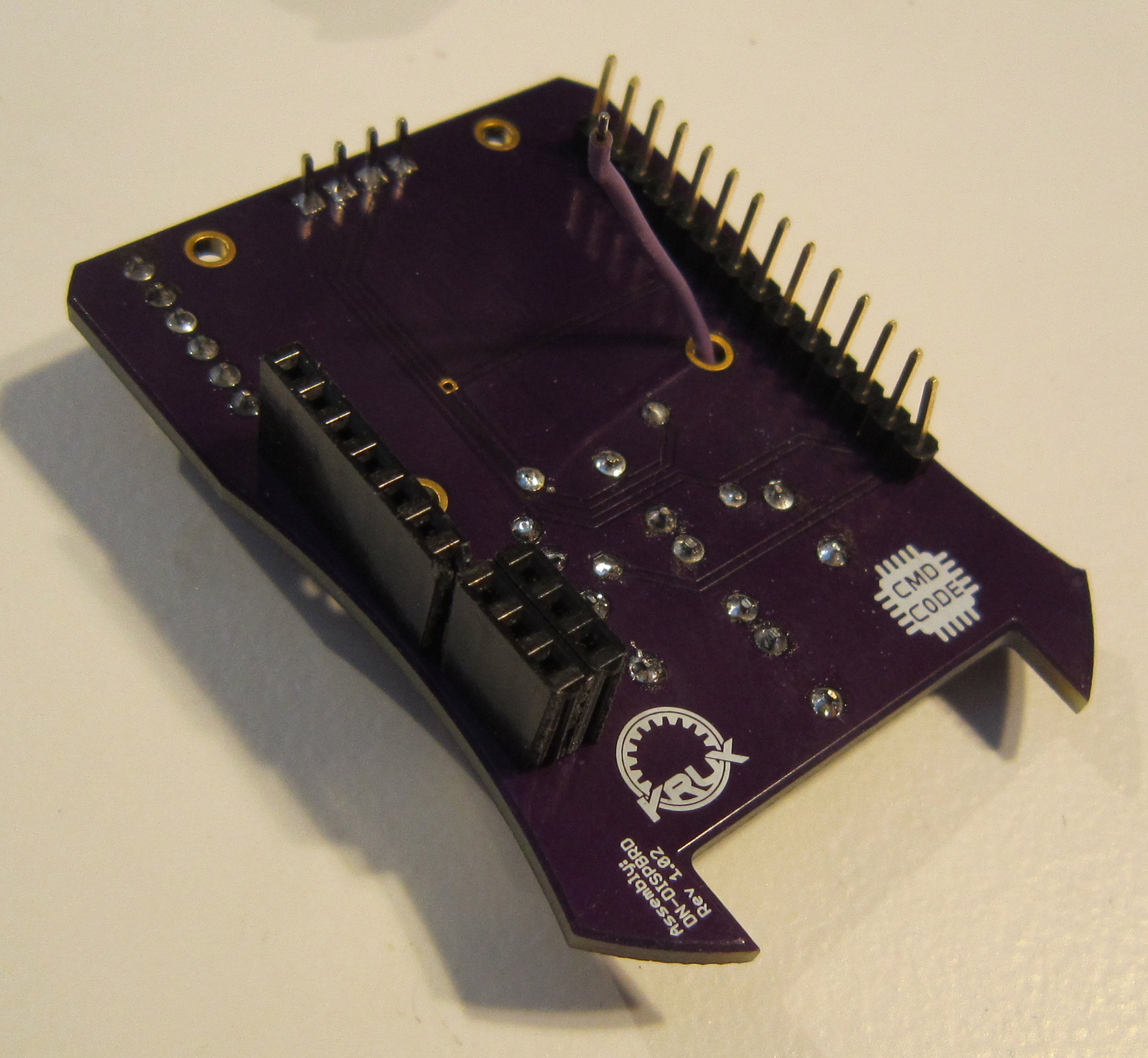
Next solder the other end of the wire to the switch pin closest to the capacitor, on the side of the board with the Krux logo.
You can now install your display board. If your badge is flashed with the latest firmware, you will have the display code.
Not all modes of the badge work with the display, so cycle through the modes by hitting the reset button.
