
These are the assembly instructions for the DefCon DarkNet 2015 Badge Kit.
This badge not only is an excellent opportunity to learn how to solder, if you do not know already, it is also a tool that is used to communicate with other agents participating in the DefCon DarkNet contest. It can be used to pair with other agent's badges, as well as is insturmental in several of the challenges you will encounter when playing with the DarkNet.
Each kit comes pre-programmed with the DarkNet firmware, and a unique GUID.
This badge was designed to be easy to solder, as well as extremely hackable. It is based on the AVR ATMega328P microcontroller. It is a fully functional Arduino, and can be programmed using a standard AVR programmer, or with a serial FTDI cable using the Ardino IDE. All the AVR microcontroller's pins have been broken out for easy access.
There are currently two add-on kits, with the badge footprint, a display shield, and a prototyping shield.
The badge hardware was developed by Krux, and the badge firmware was developed by Smitty, and CmdC0dez.
Avoid common mistakes, and read through this guide in it's entirety before beginning.
You will need the following tools to assemble this kit
- Temperature controlled soldering station
- Fine solder, 0.032" diameter or smaller
- De-soldering pump / de-soldering braid
- Flush cut wire cutters
- Needle nose pliers
- Fine point tweezers
- Safety glasses
- Optional: PCB vice
- Optional: Flux for SMD use
- Optional: Denatured alcohol to clean the board after soldering
When soldering, it is important to always follow safe work habits. Be mindful of yourself and others. The following documents address some of the safety concerns when soldering
- Soldering Safety
- Lead Soldering Safety Guidelines
- Lead-Free_Solder_Fumes_Increase_Need_for_Fume_Extraction
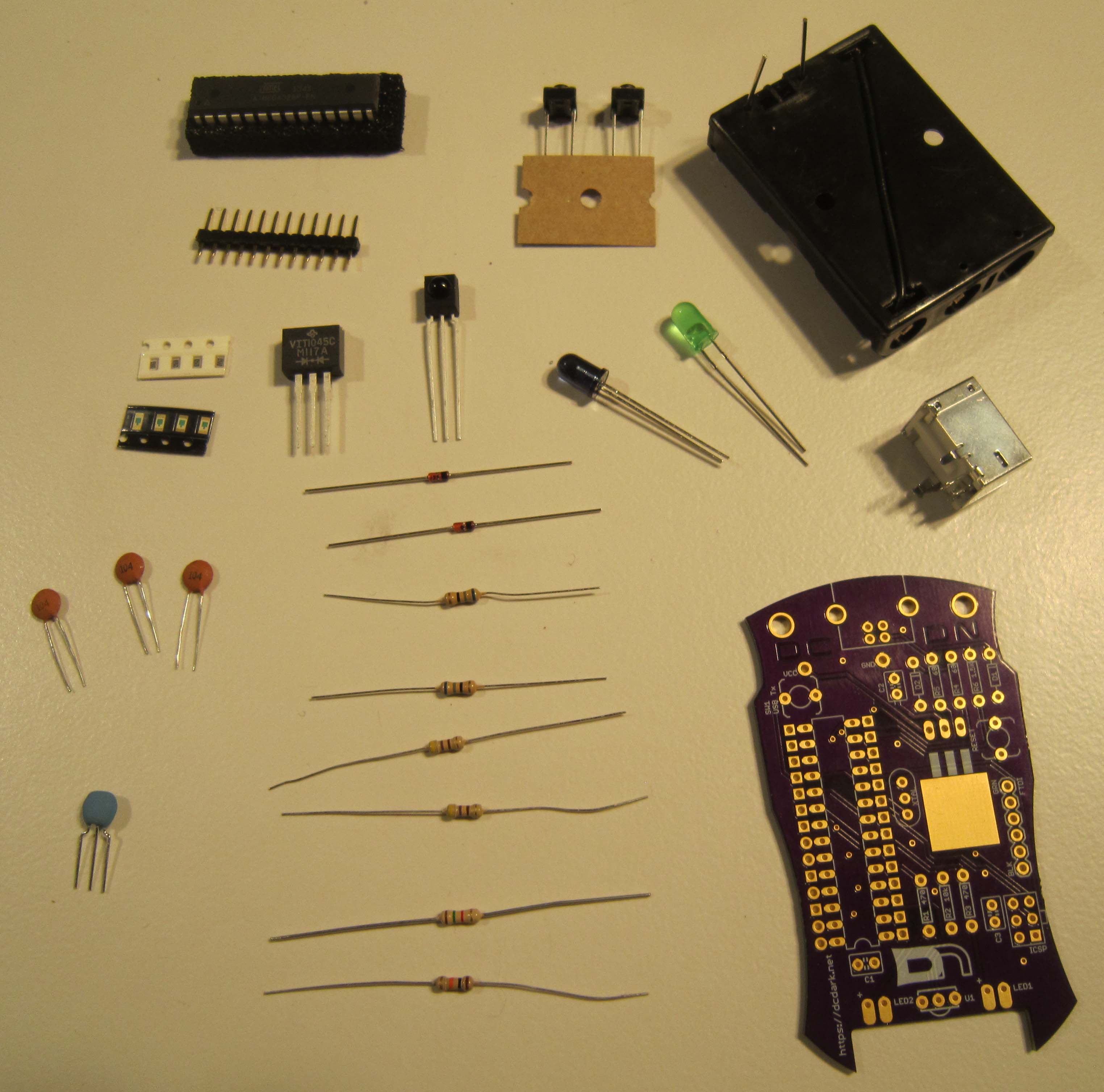
Before you get started, take a moment to ensure that all the components have been included with the kit.
Note: This is also a good time to turn on your soldering iron. For leaded solder, 320 degrees Celsius is a good working temperature.
- One Printed Circuit Board [in OSH Park purple]
- One ATMega328p Microcontroller
- One 3-Cell AAA battery holder
- Three AAA batteries
- One 5mm Green LED
- One 5mm Vishay IR LED
- One Vishay IR Receiver Module
- Two 68 Ohm 1/4W 5% carbon film resistors [Blue Gray Black]
- Two 470 Ohm 1/4W 5% carbon film resistors [Yellow Violet Brown]
- One 10K Ohm 1/4W 5% carbon film resistor [Brown Black Orange]
- One 1.5K Ohm 1/4W 5% carbon film resistor [Brown Green Red]
- Two 3.6 volt 1/2W 5% Zener Diodes
- One VIT1045C-M3/4W Dual Schottky Diode TO-262AA
- Three 0.1UF 50V Ceramic Disc Capacitors
- Two Tactile Switches SPDT
- One Murata Electronics Resonator 16.00MHz 0.5%
- One USB Type B Connector
- Four SMD 0805 470 Ohm thin film resistors
- Four SMD 0805 Lite-On white LEDs
- One 12 position male header
- One 3ft USB 2.0 A Male to B Male
- One DefCon DarkNet Lanyard
Click on any of the images for a high-resolution version.
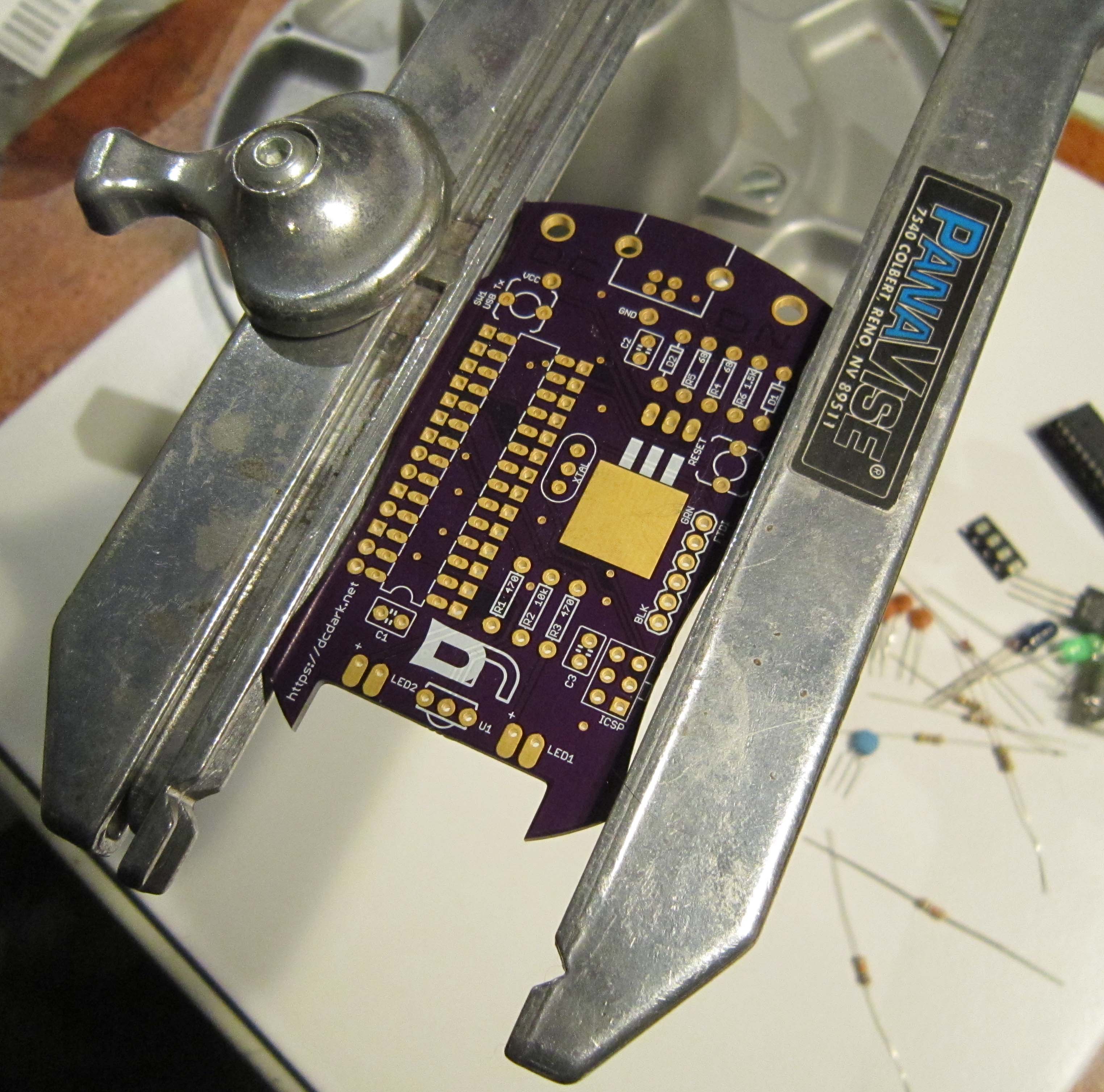
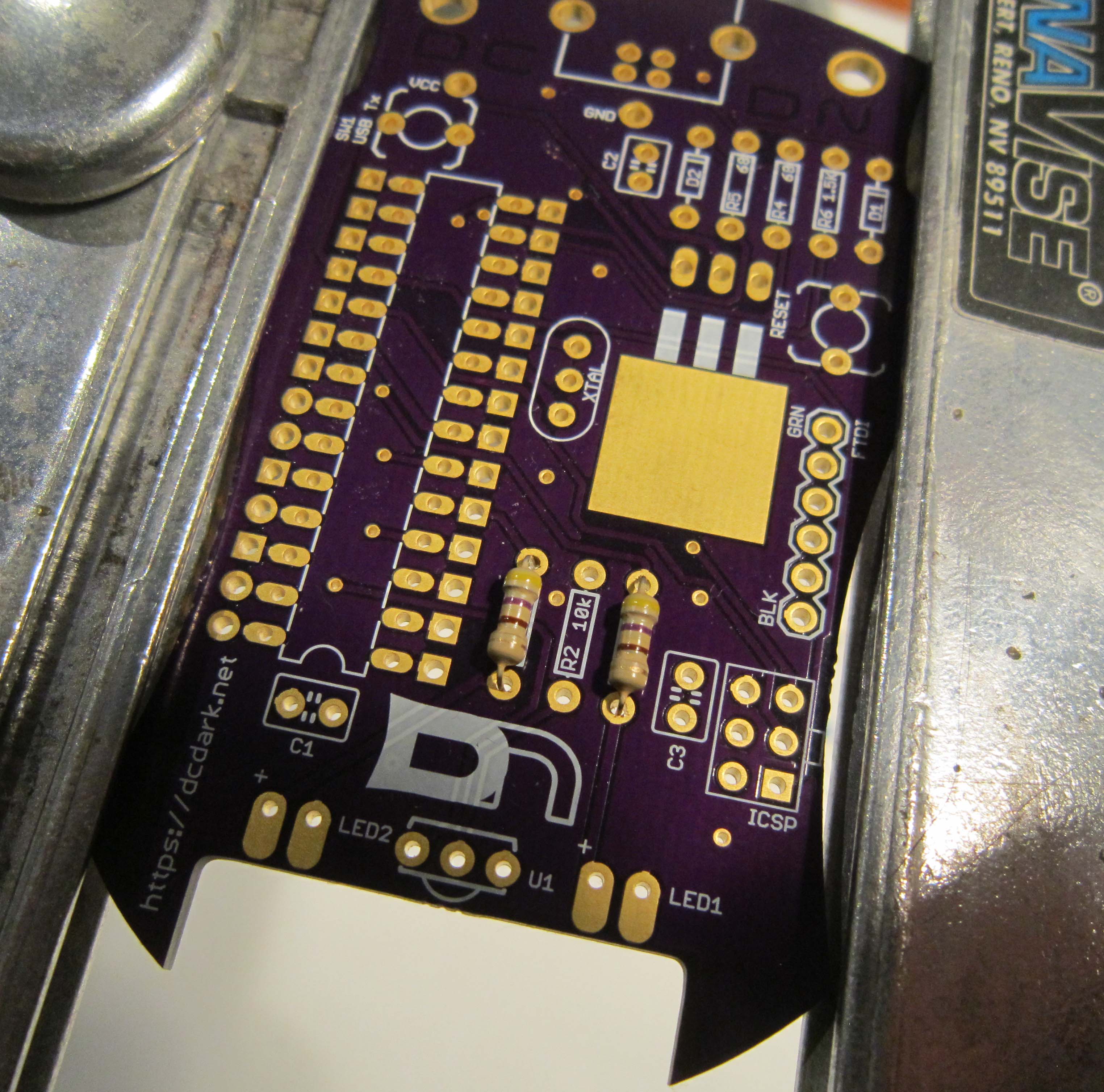
Utilizing a PCB vice as shown is useful, but not required for the assembly of this kit. Common practice when a PCB holder is not available is to add the components from smallest component to largest. This lets you utilize the weight of the PCB in order to keep components in place when soldering. This guide makes use of this technique.
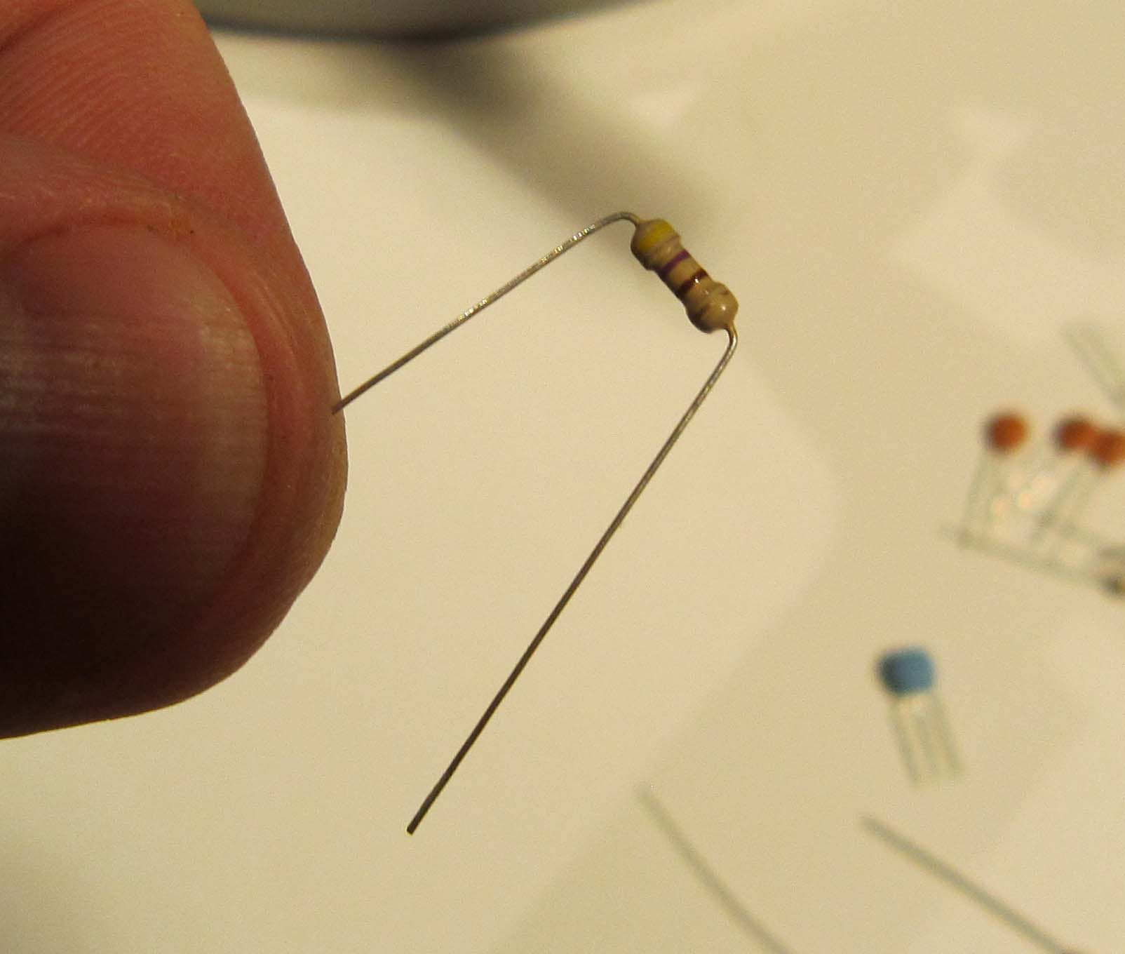
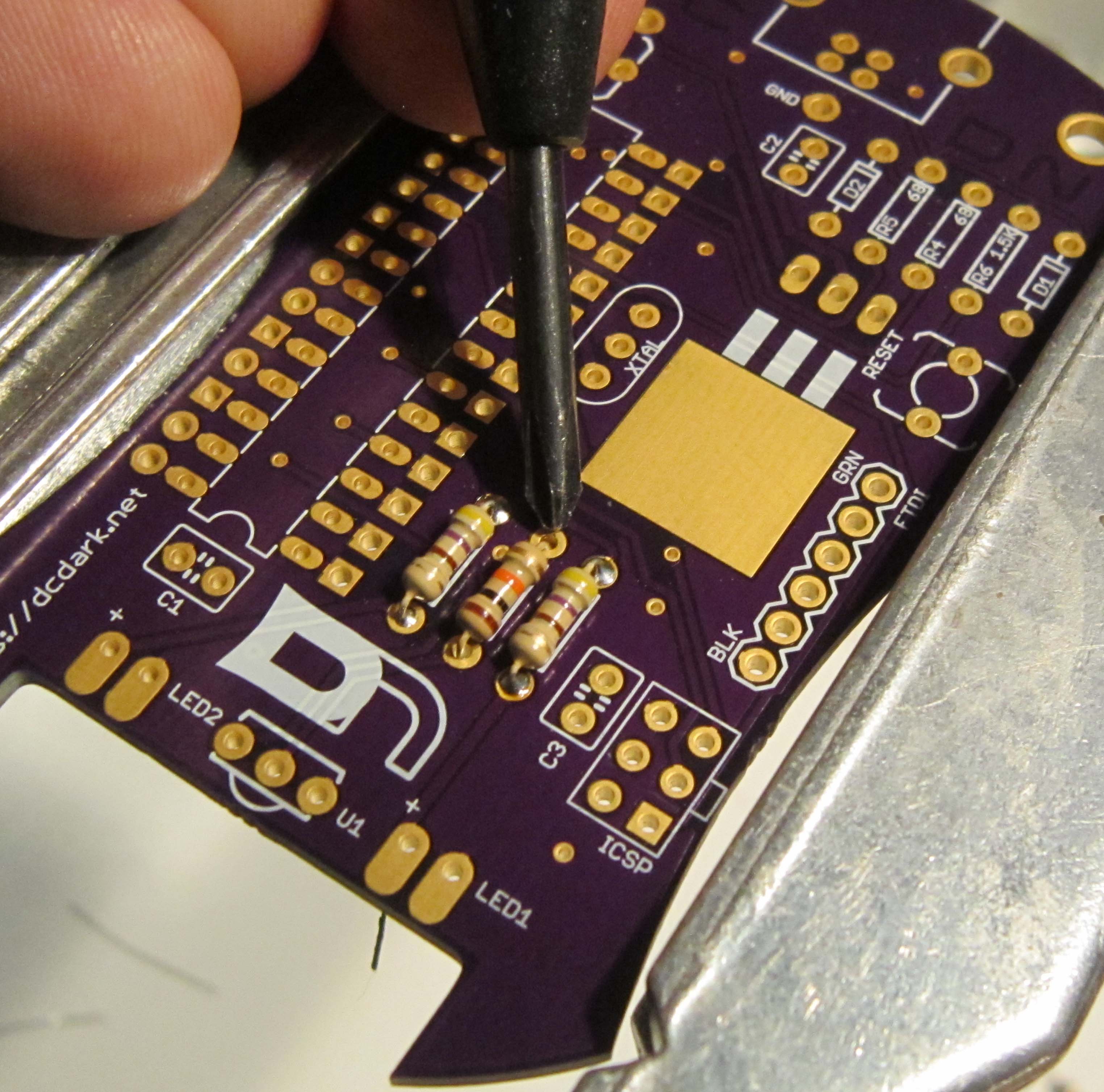
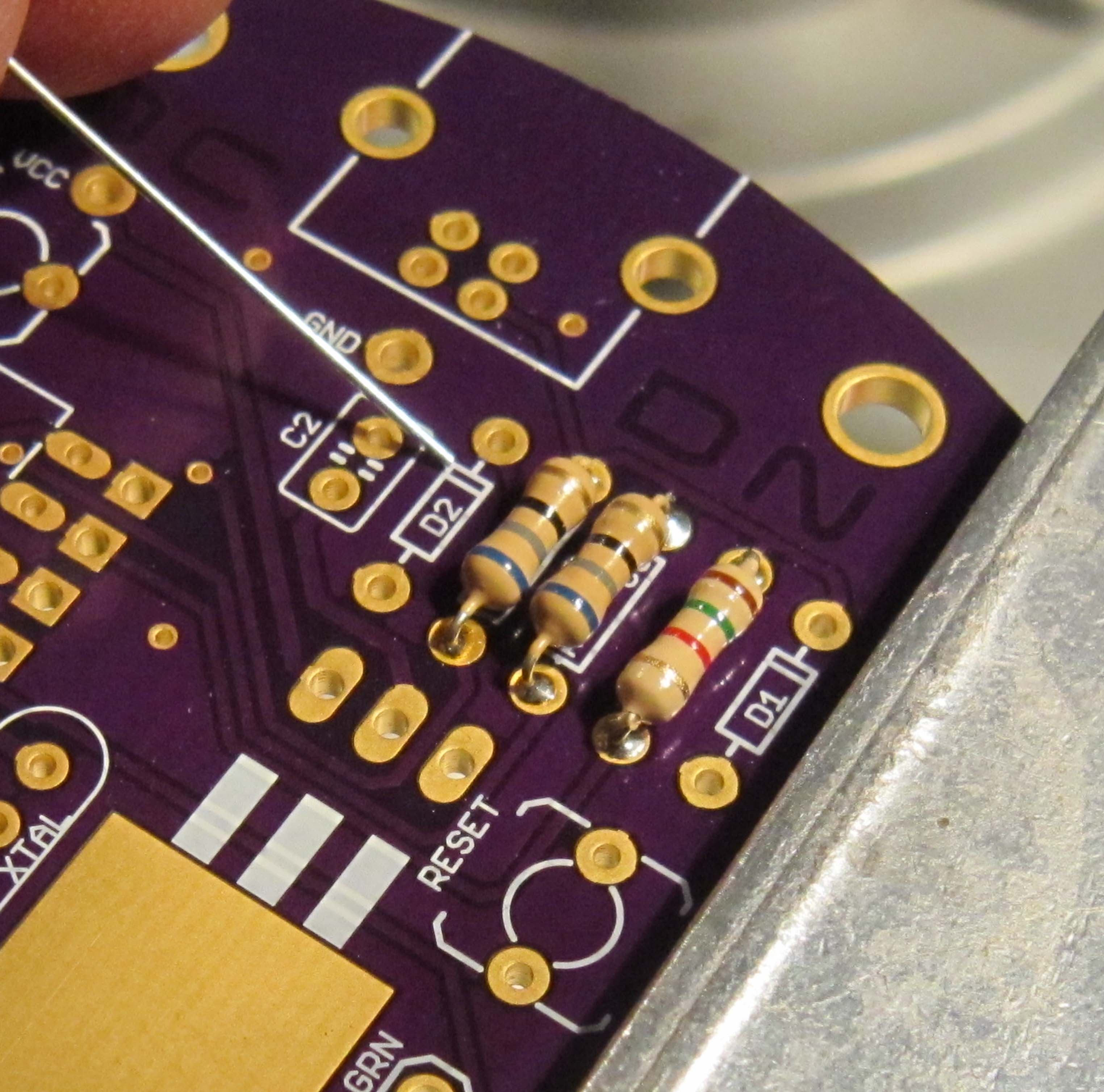
Start by soldering the 470 Ohm resistors R1, and R3. They can be identified by their yellow violet brown resistor color code. Resistors do not have a polarity and can be installed in either direction.
The following resistor color code chart is useful in identifying resistors values.
Start by bending the leads as shown, so they may be inserted into PCB.
Populate the components, so they are on the top side of the board. Each component is marked with it's part designator. The resistors also include their required value. The parts should lay flush with the PCB.
To aid in soldering, and to help keep the components in place, the leads may be splayed at a slight angle to hold the parts in place. Double check that the parts are still flush with the PCB before soldering.
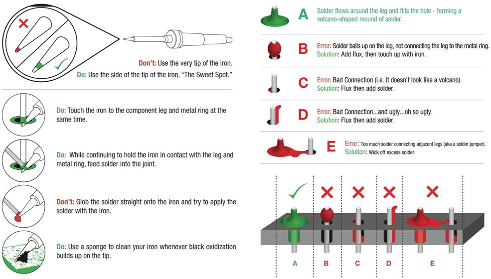
Ensure the tip of your soldering iron is always kept clean. It should be shiny in appearance. Removing the oxidation by wiping the soldering iron on a solder sponge.
When using a chisel tip as show, the flat of the tip can be used. When using a conical tip, use the section of the iron just to the side of the tip. This gives you a larger area of thermal contact and will make soldering easier.
Begin soldering by positioning the tip of the iron so that it makes firm contact with both the solder pad on the PCB and the lead of the component. This ensures that both the pad and the part both get sufficiently hot so that they are able to melt the solder and make a good electrical connection. Feed solder in sparingly on the side opposite the soldering iron. The solder should flow on the solder pad and lead of the component, forming a conical shape.
The following diagram shows more details on soldering DOs and DON'Ts
Next trim the resistor leads close to the board. This should be where the component lead meets the solder, as shown here.
Safety Tip: When cutting component leads, ensure that you are holding the lead when you cut the part to prevent the lead from becoming a projectile. Not doing this can lead to eye injury for yourself or others. You can easily do this by holding a finger tip over the lead as you cut it.
Next solder in the 10K Ohm resistor R2. The resistor color code is brown black orange.
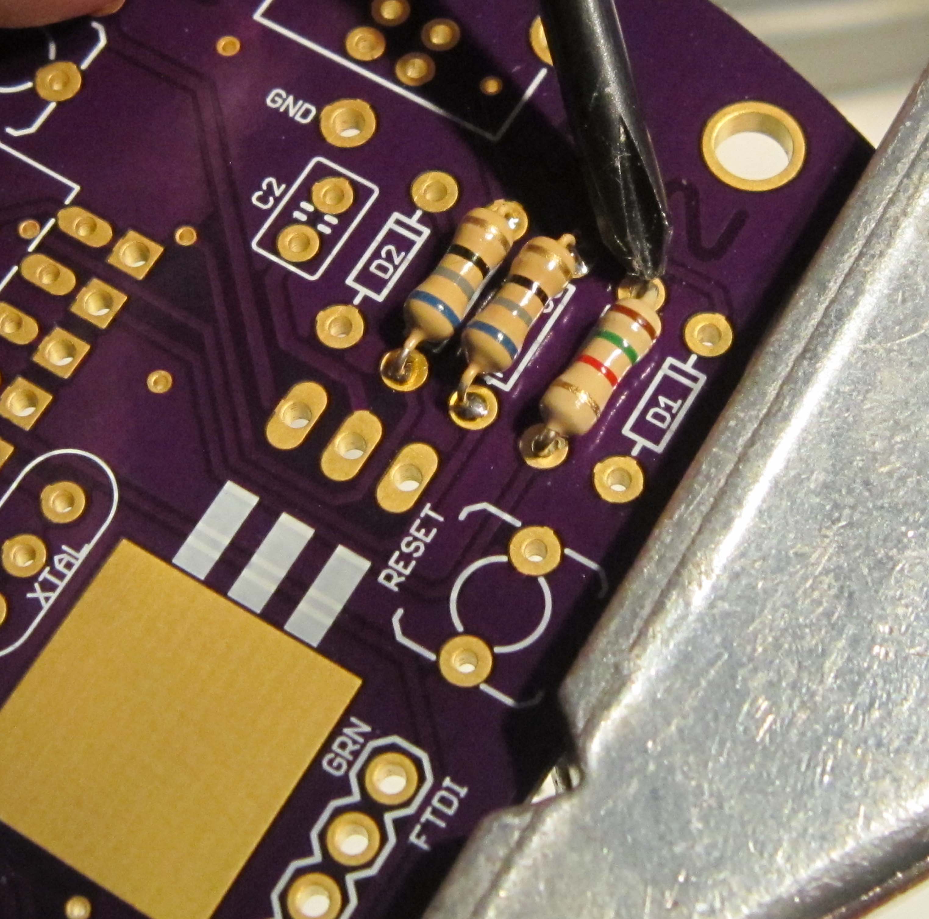
Next solder in the two 68 Ohm resistors R4 and R5. The resistor color code is blue gray black.
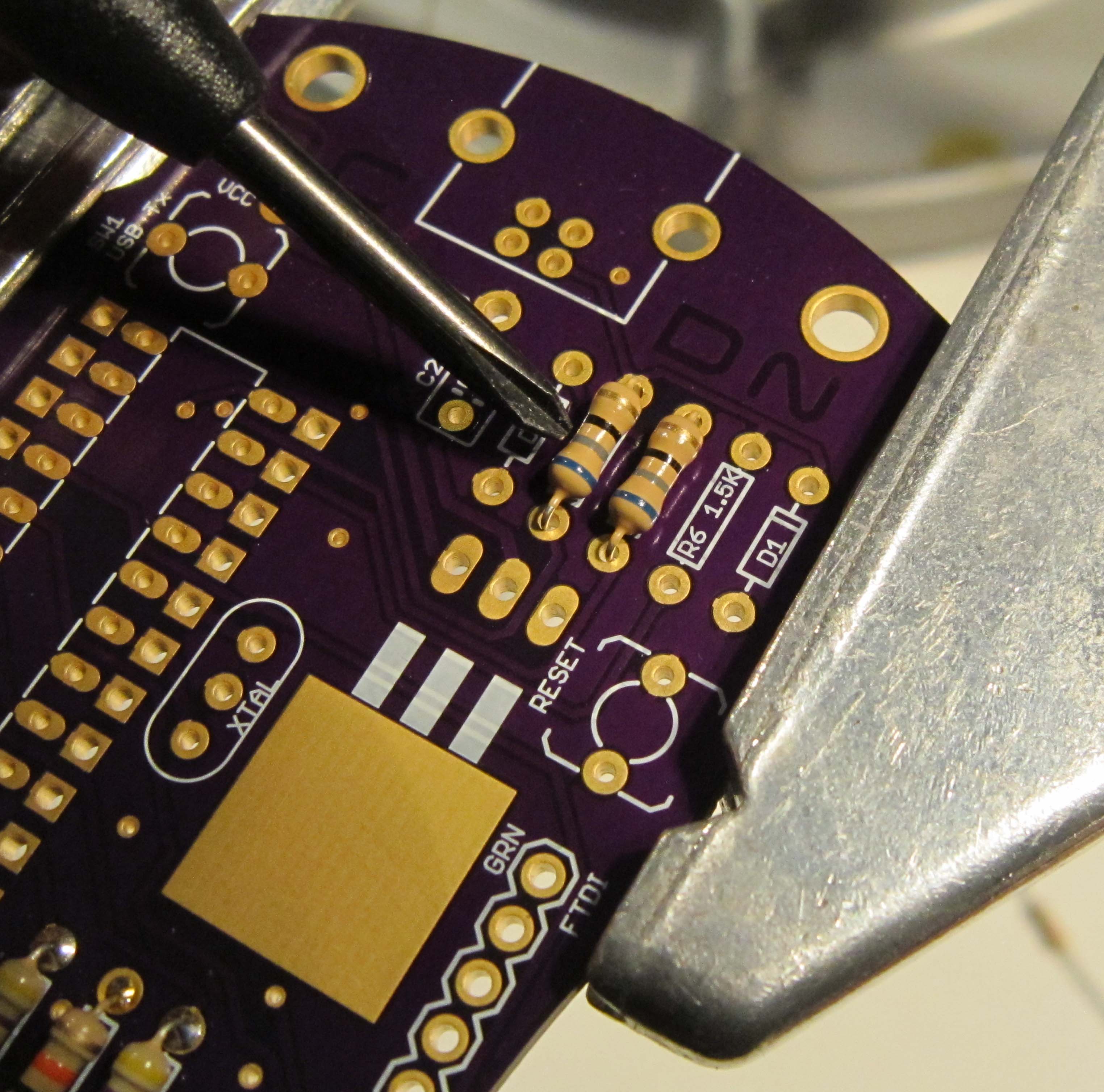
Next solder in the 1.5K Ohm resistor R6. The resistor color code is brown green red.
Next we will solder in the two zener diodes, D1 and D2. Unlike the resistors, diodes are polarized components. This means that the direction they are installed is important.
The polarization can be determined the the presence of a black stripe on one end of the zener diode.
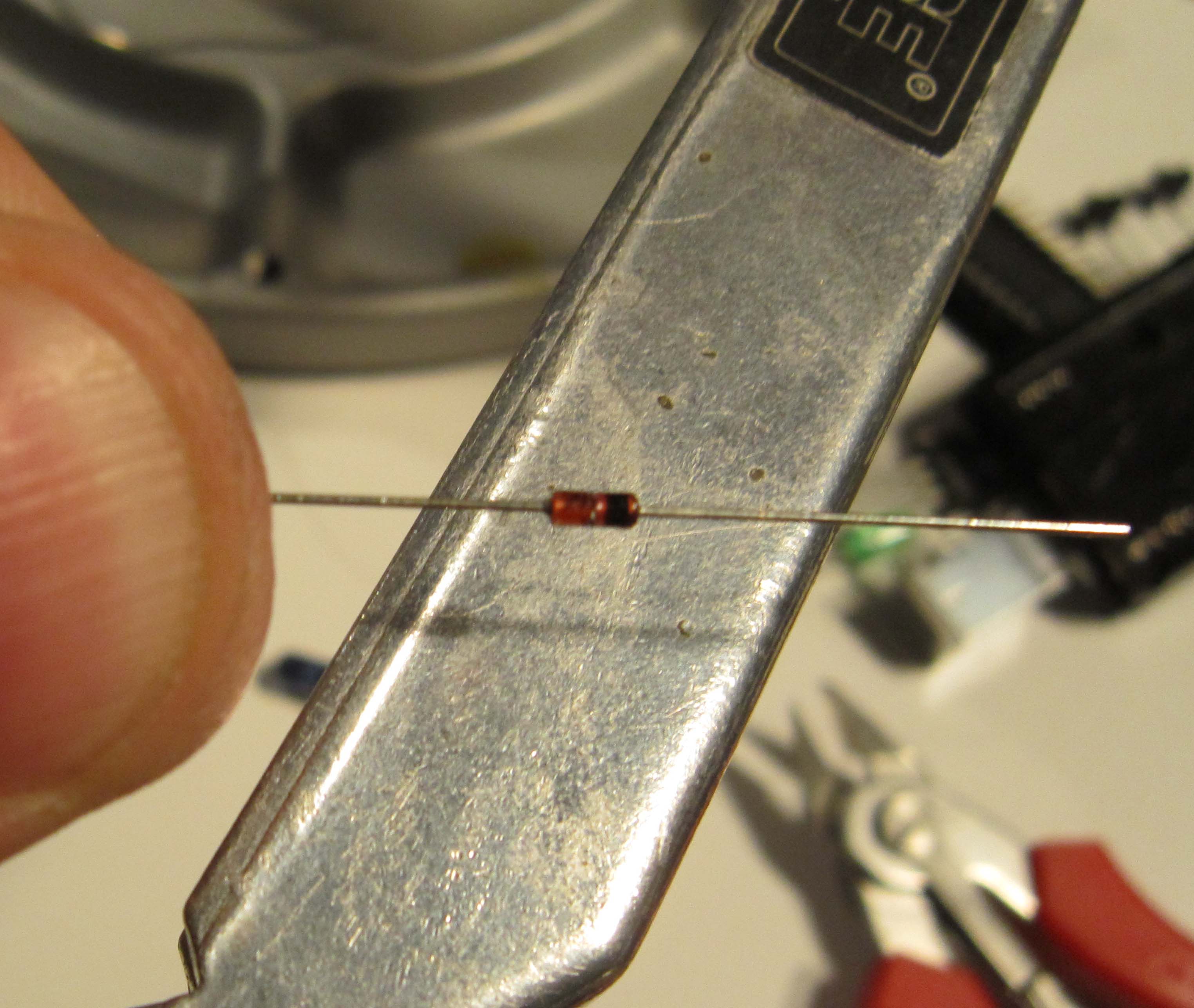
On the silk screen marking on the PCB, there is also a corresponding stripe.
Install both diodes as shown
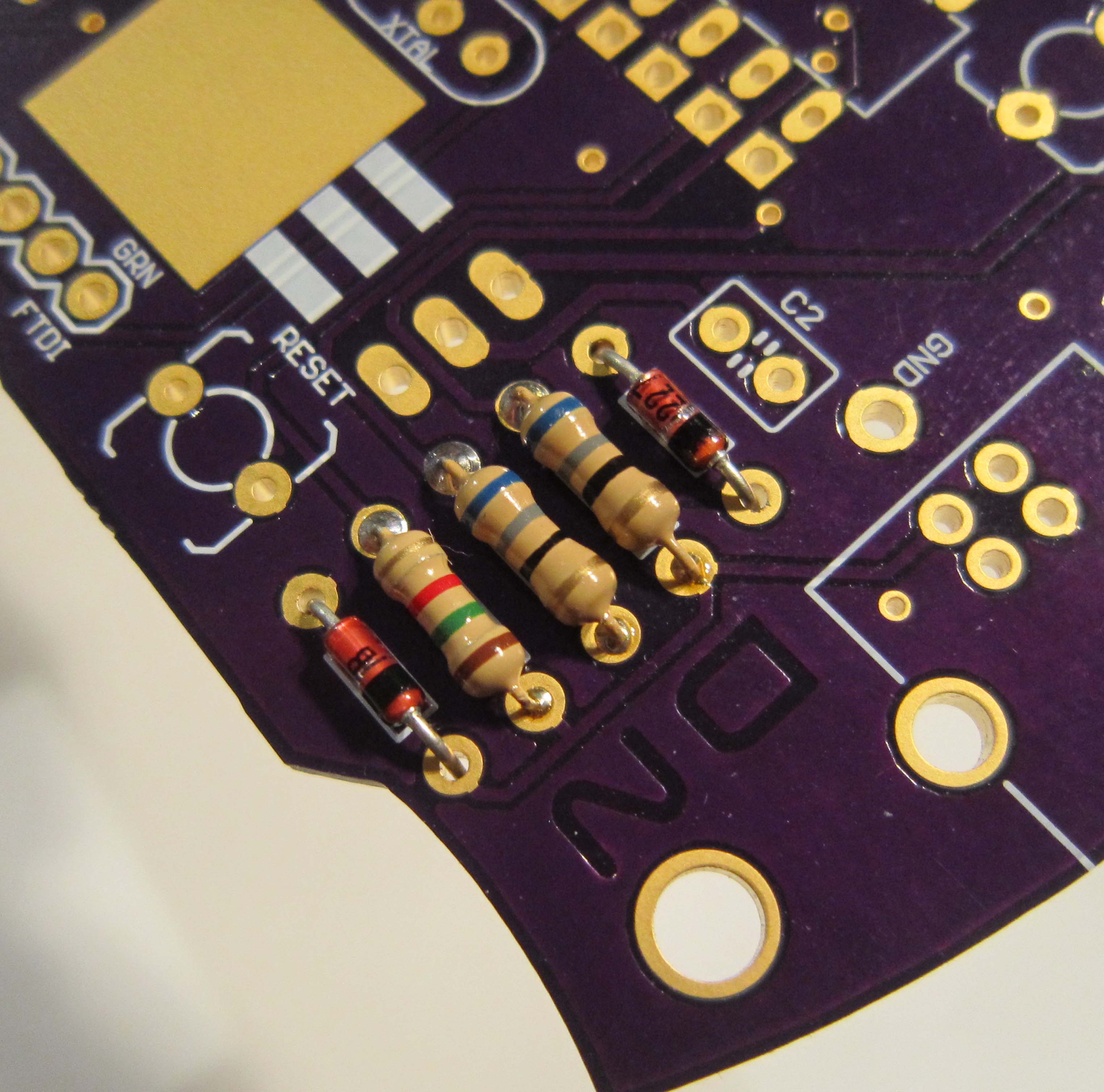
Solder and trim the leads as you did with the resistors.
Next we will solder in the three capacitors, C1, C2, and C3. Capacitors can be polarized or non-polarized. The capacitors included in this kit are non-polarized and may be installed in either direction.
Install the capacitors as shown.
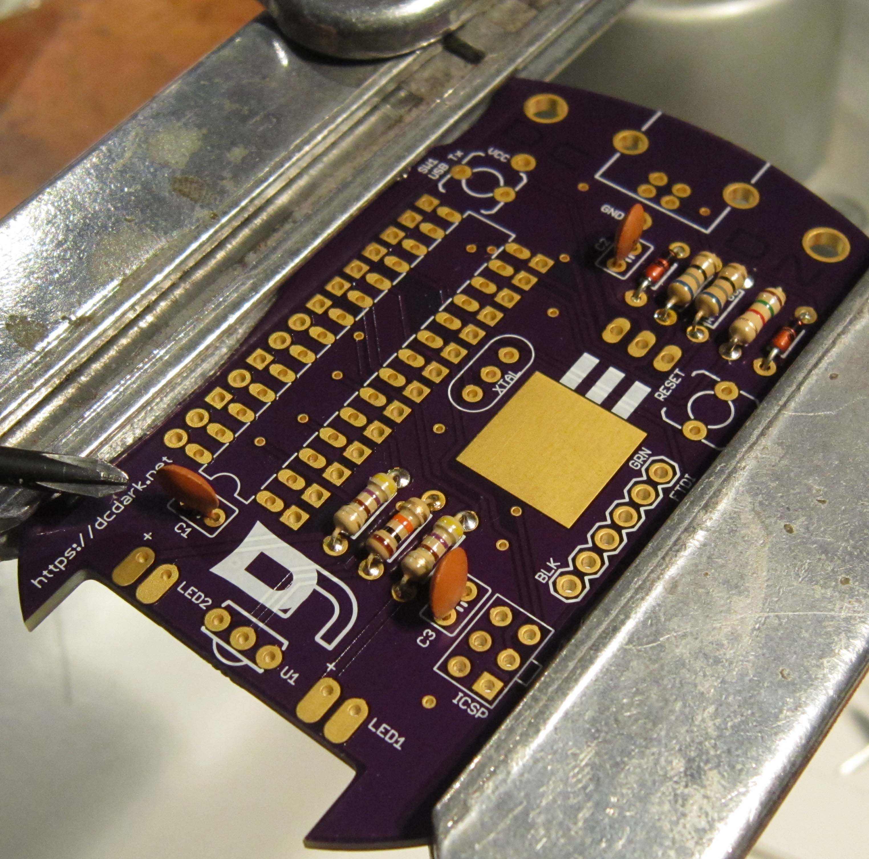
Solder and trim the leads as you did with the other components.
In order to allow this kit to be connected to your computer, while also being battery powered, a diode bridge is used. This ensures that voltage from the computer does not feed into the batteries. And also protects the circuit if the batteries are inadvertently installed backwards.
This package is installed so it lays flat to the PCB. The leads on this part will be bent at a 90 degree angle so that there is enough lead to mount the heat sink of the part on the square solder pad. The leaded edge of the part should align with the edge of the pad.
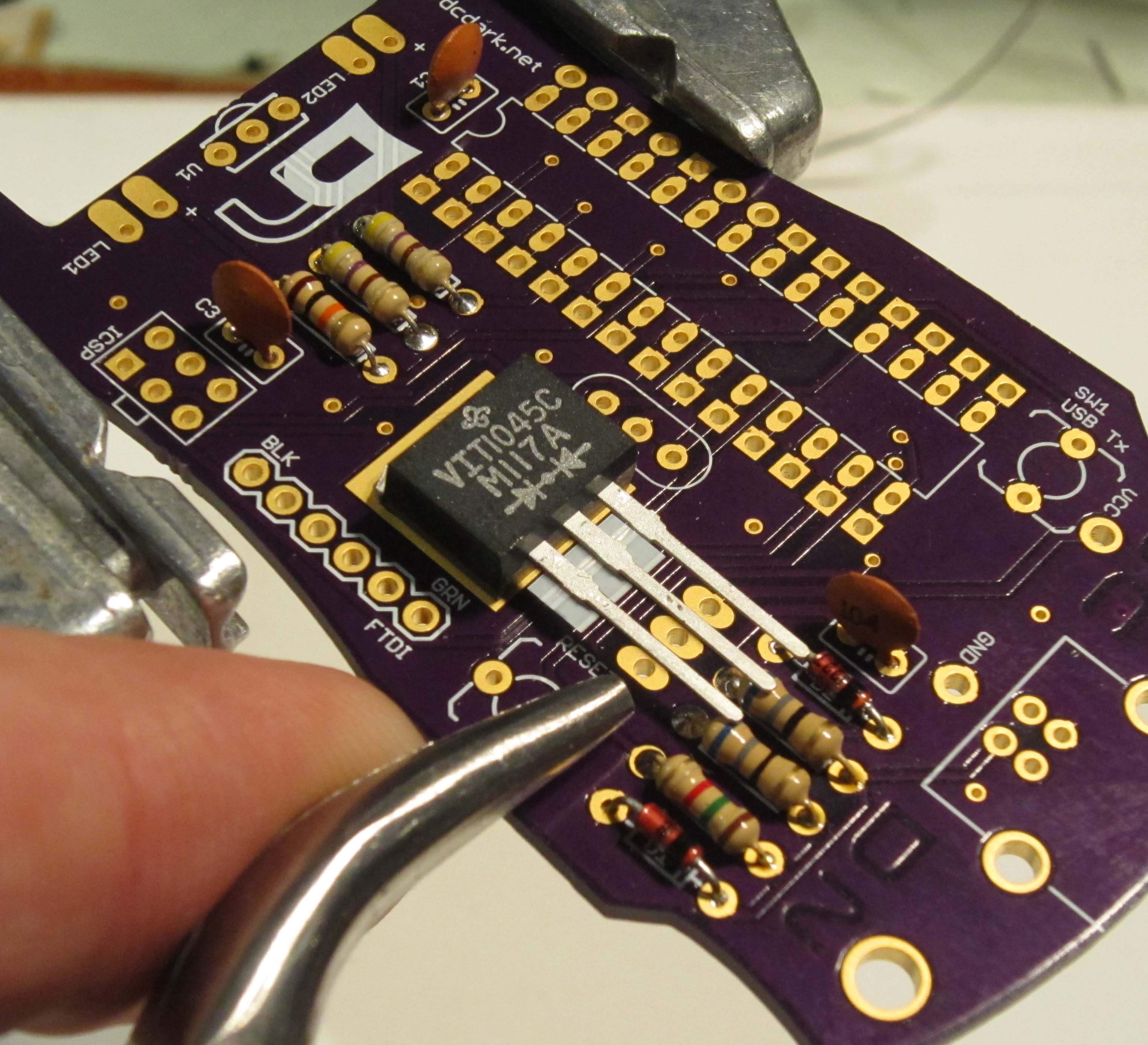
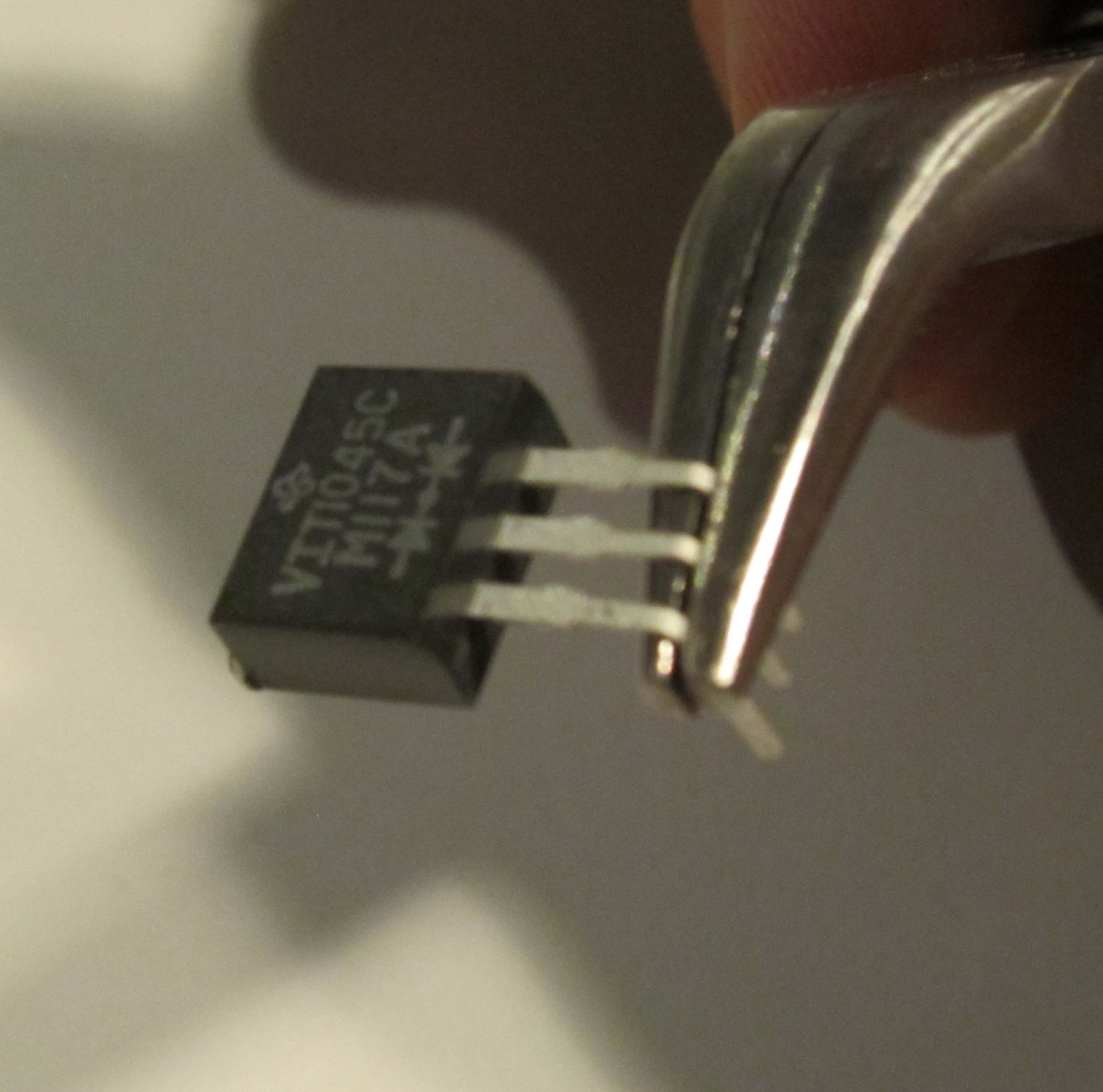
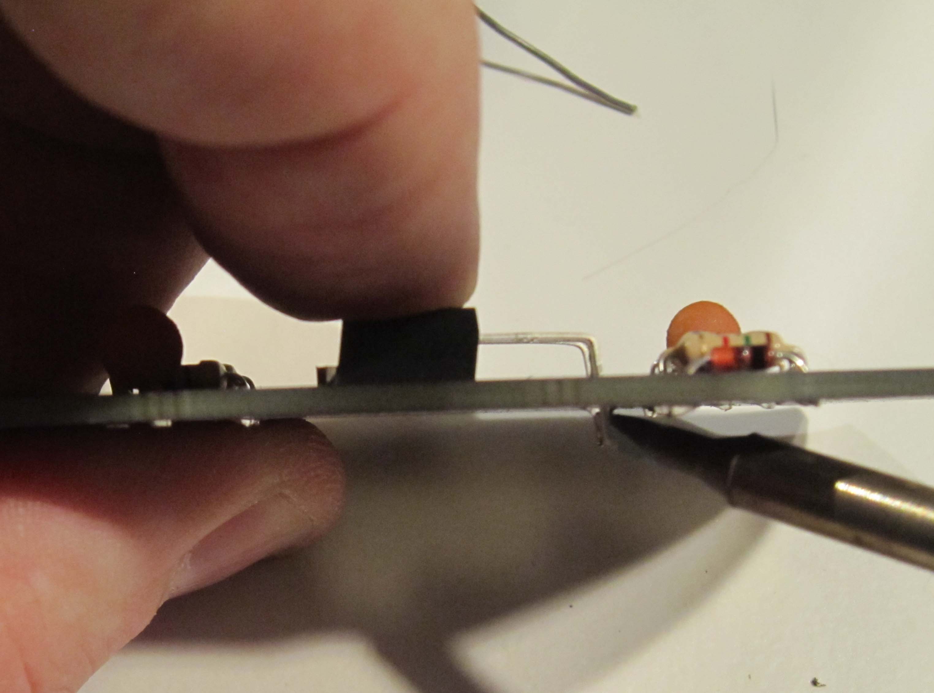
Using needle nose pliers, grasp the leads where the are above the three solder pads for the component.
There should be 7.5mm of lead between the pliers and the component.
Bend the leads over as shown.
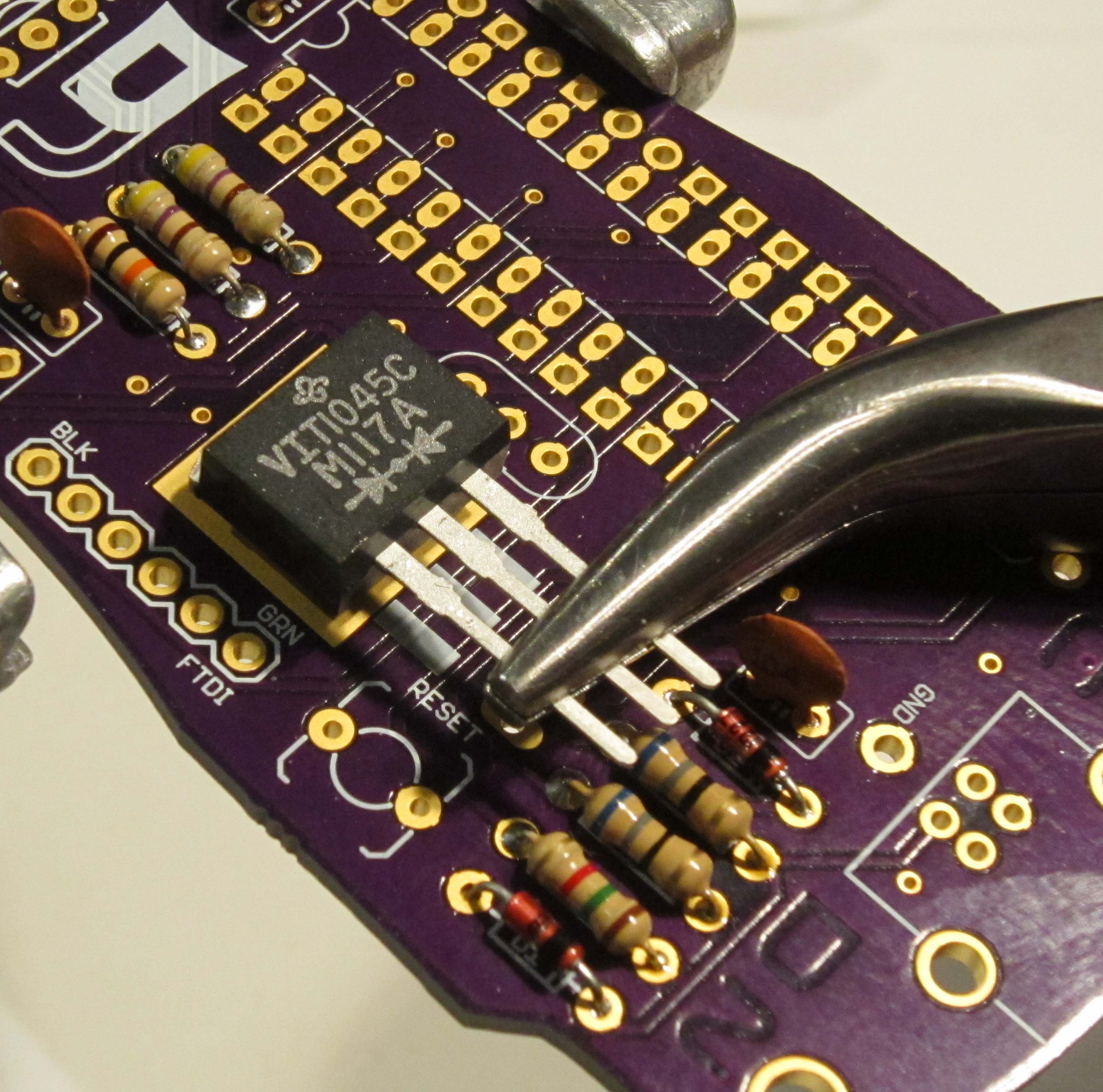
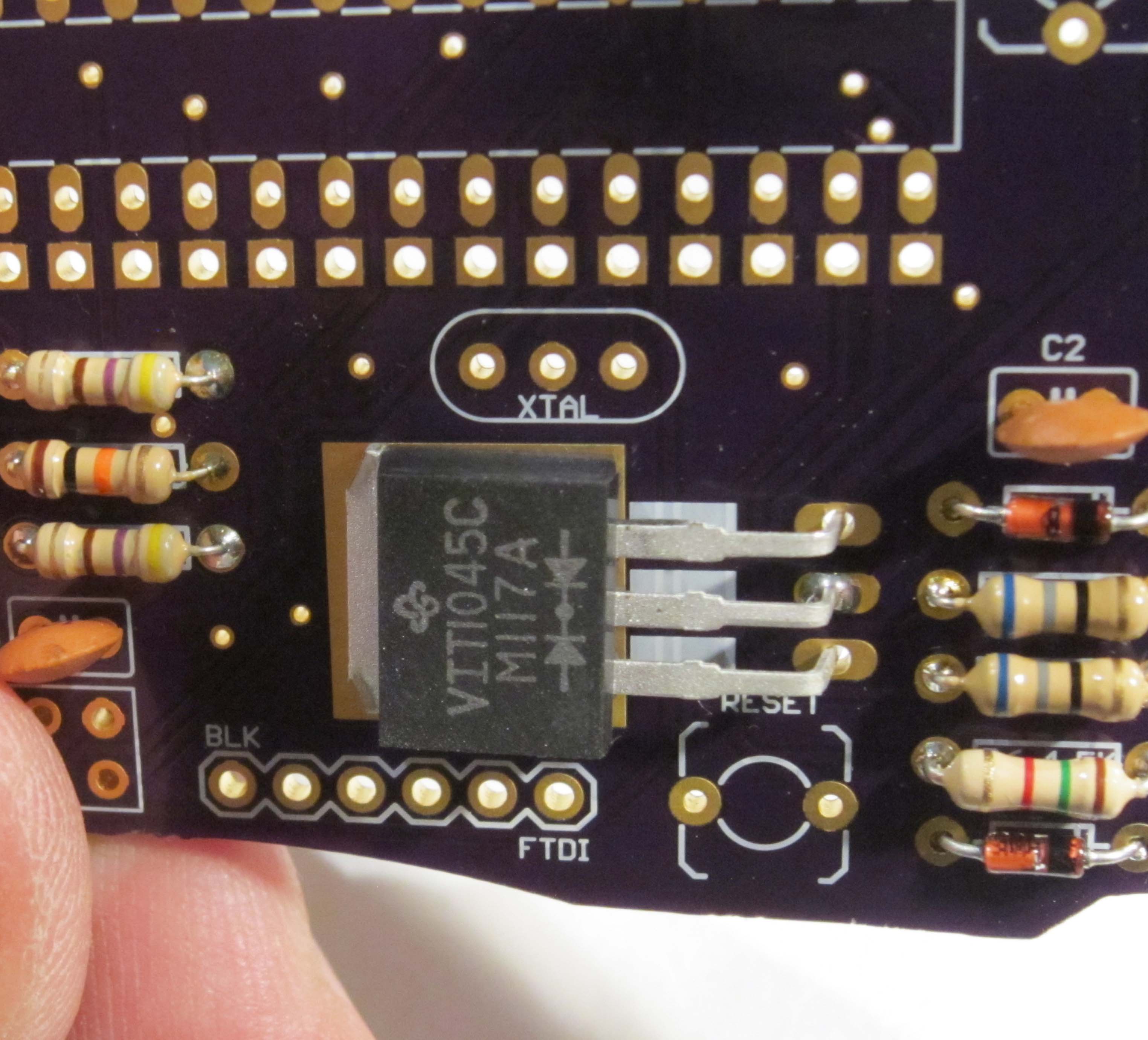
Next install the part onto the PCB as shown. If done correctly there should be enough pad showing at the tab of the component so it may be soldered, and the entirety of the componet will be on the pad.
Next solder one of the leads of the diode bridge.
We only are soldering one part, since we will adjust it's position if needed in the next step.
If the diode bridge is not laying flat against the PCB, heat the soldered lead and adjust by pressing flat.
Check that the part is positioned on the pad correctly. As only one lead is soldered it can be shifted as needed.
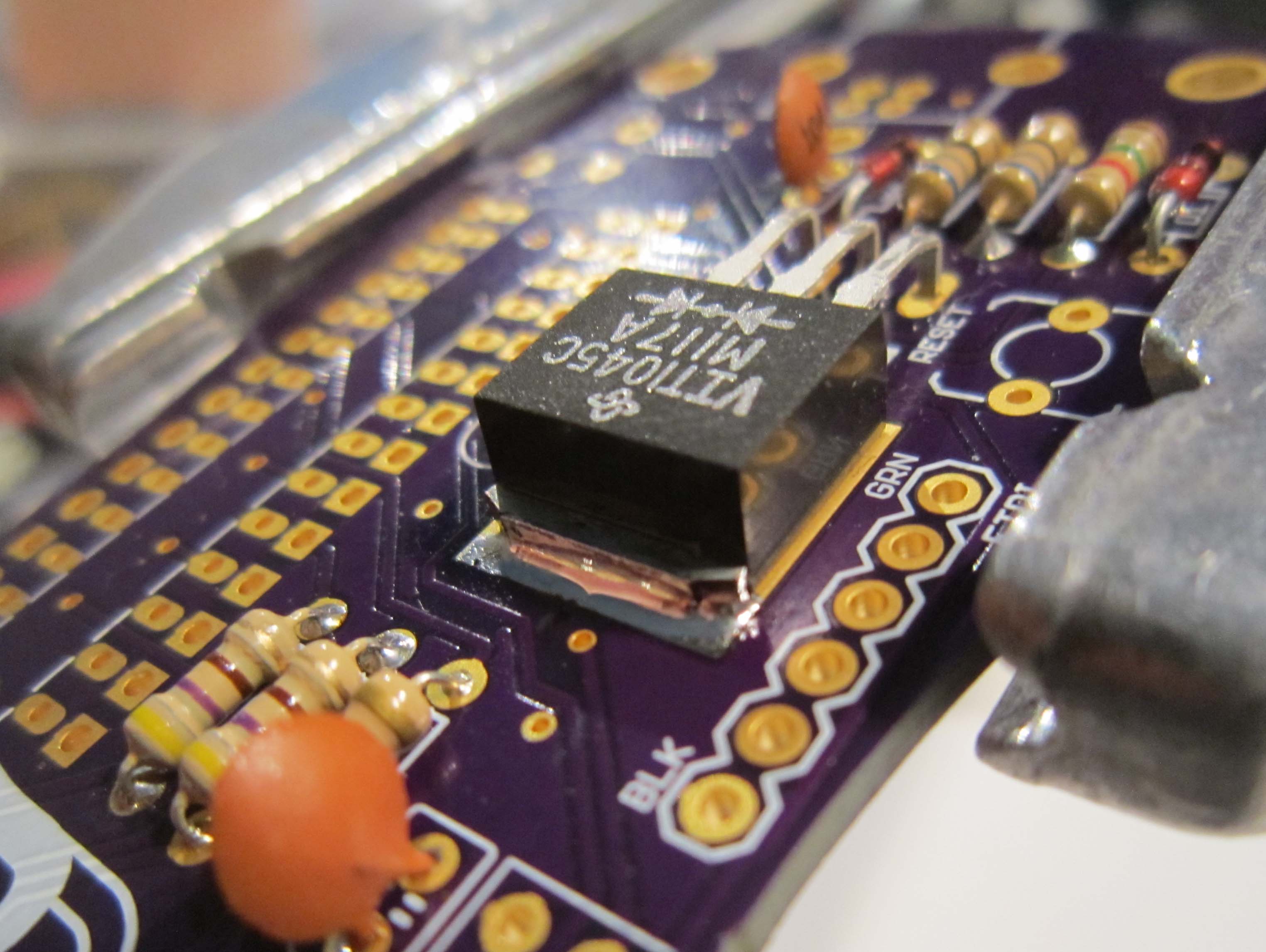
Before soldering the remaining two leads, we will solder the tab of the component in place.
As this part has a relatively large thermal mass, it will require more time to heat up to the point where the solder will melt. Place the iron so that it is laying along both the tap of the part, and the solder pad. After a few seconds add solder, and slide the tip of the iron along the interface between the component tab and the pad.
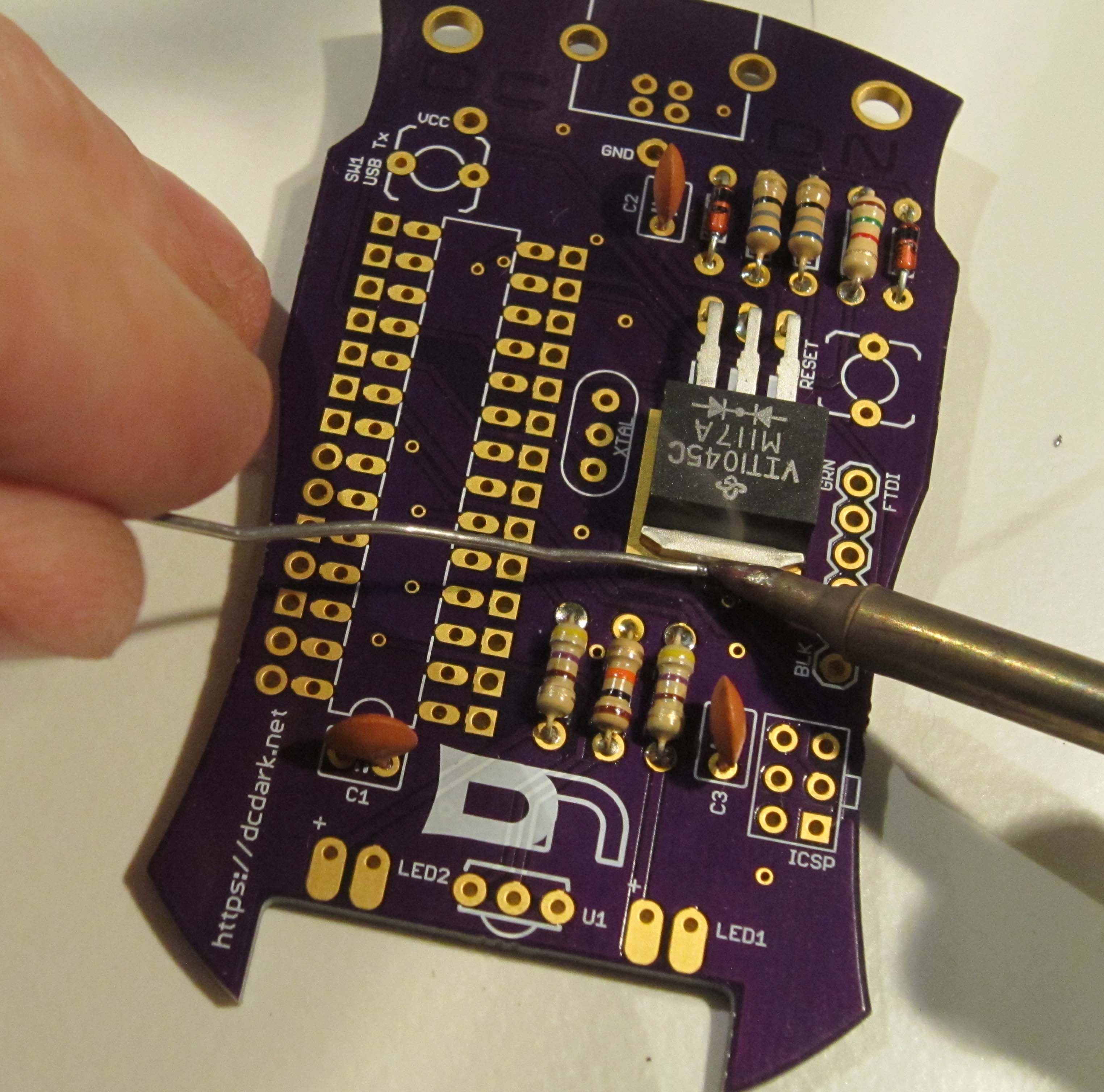
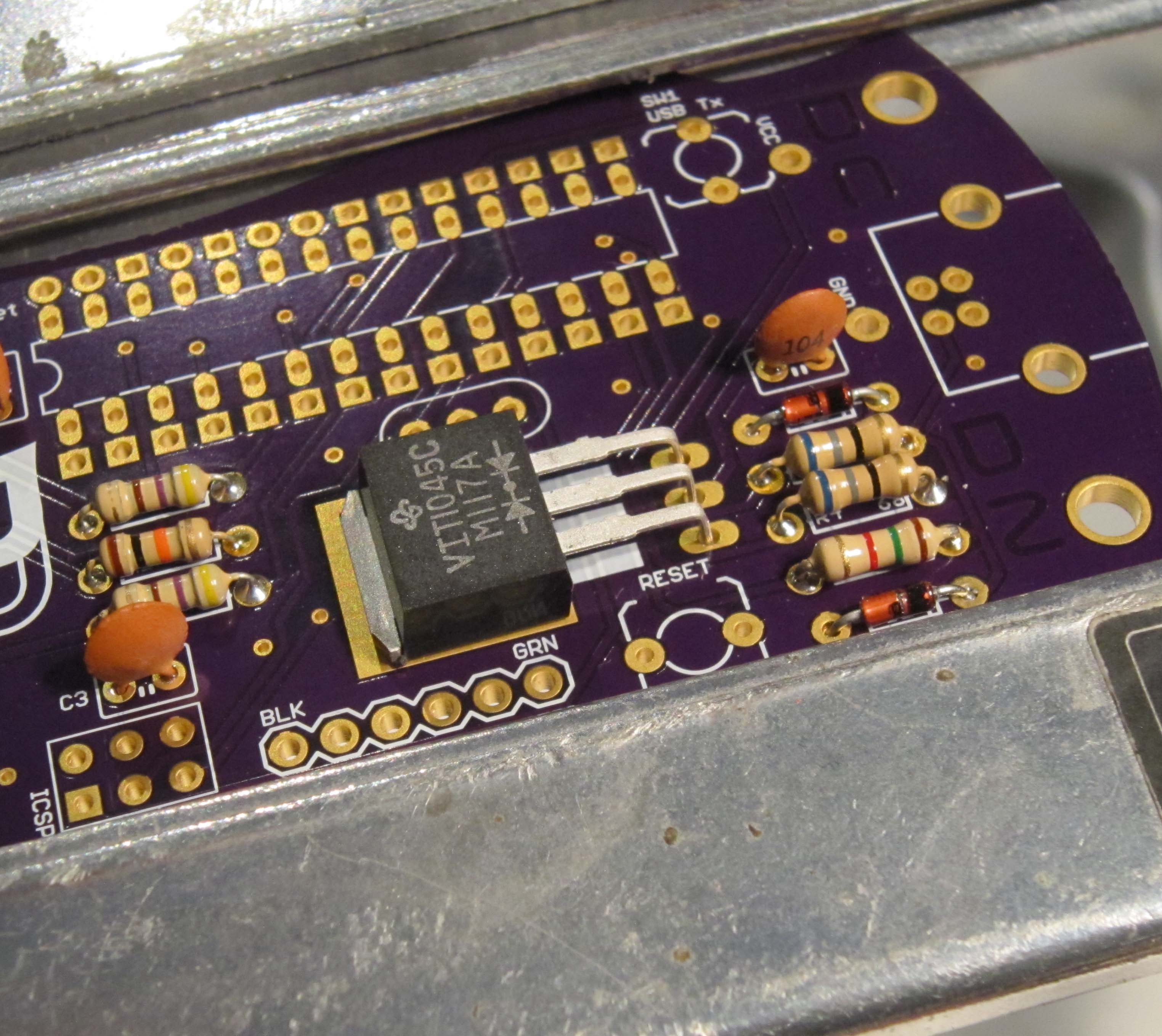
Once sufficently hot, the solder should flow so that it covers the tab and the top of the pad.
Now solder the remaining two leads, and trim flush.
The next part to add is the crystal resonator. This part is not polarized, so it may be installed in either direction.
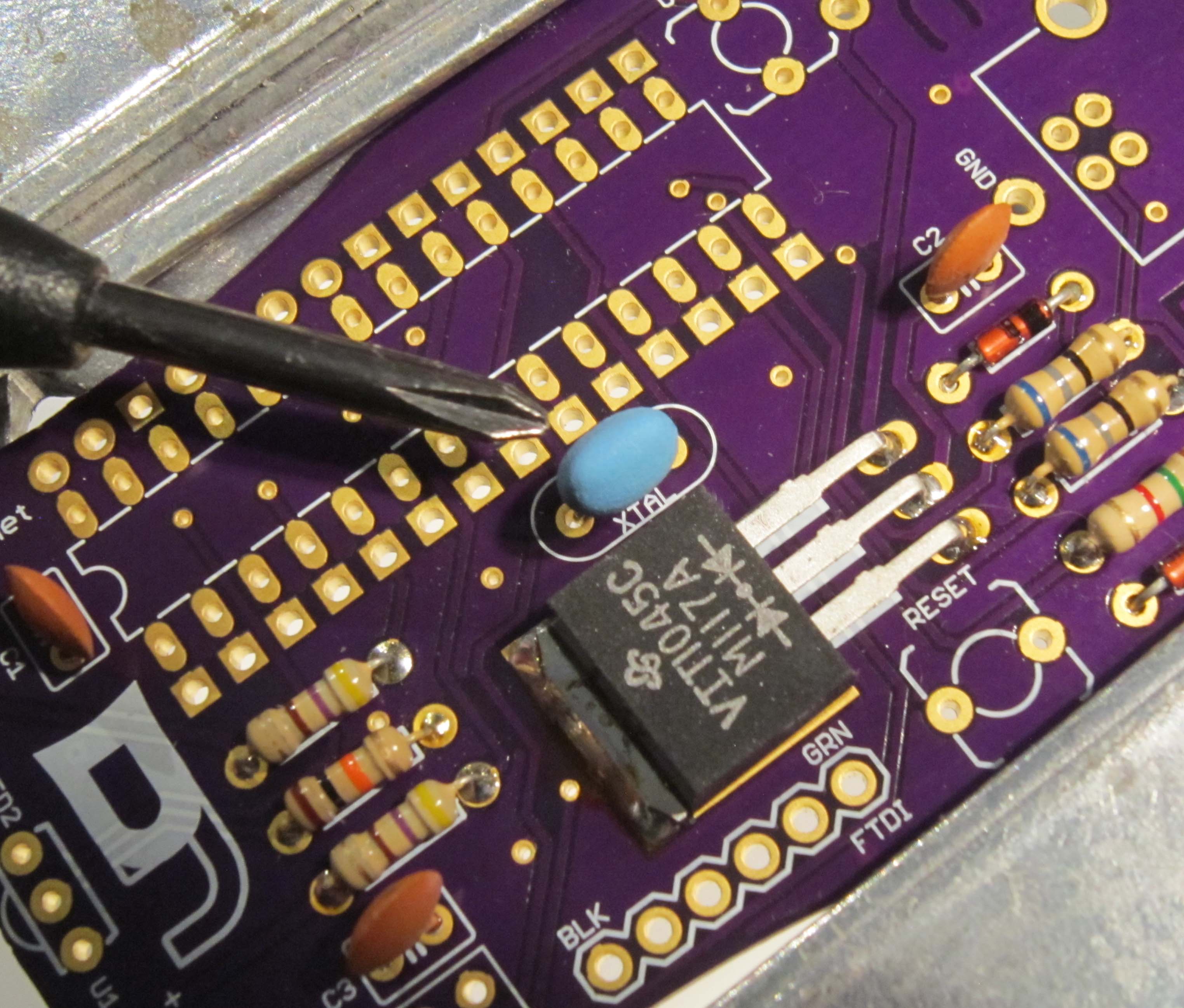
Solder and trim the leads as you did with the other components.
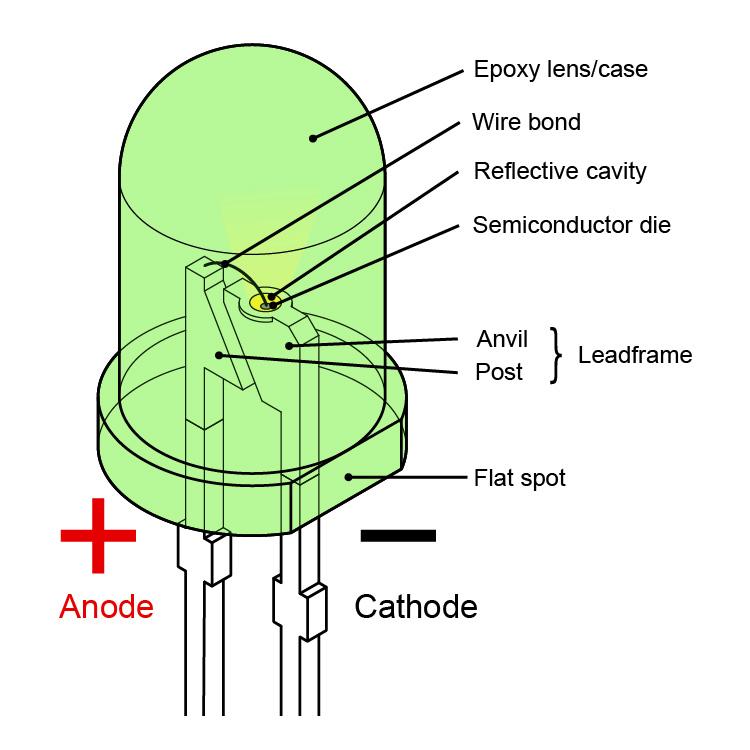
Next we will be installing the green and infrared LEDs. LEDs are polarized, and will only work if installed correctly.
The polarity of LEDs can be determined using two methods. The leads of the LED are differing lengths, with the longer of the two leads indicating the Anode, or positive lead.
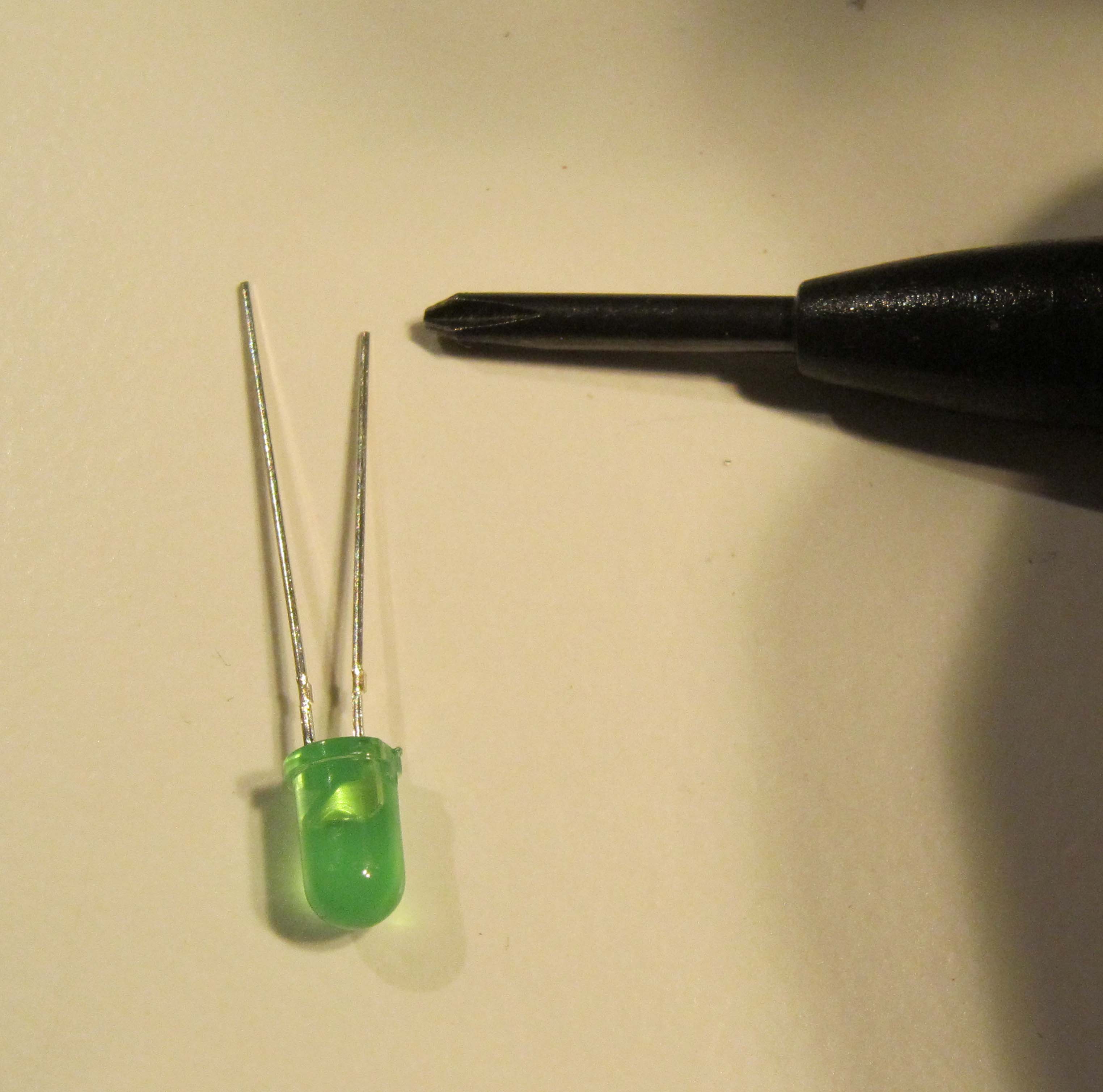
The second method is by determining the flat spot of the LED. This indicates the Cathode, or negative lead.
We will be installing the green LED at LED2.
The Anode is marked with a + to indicate the positive lead.
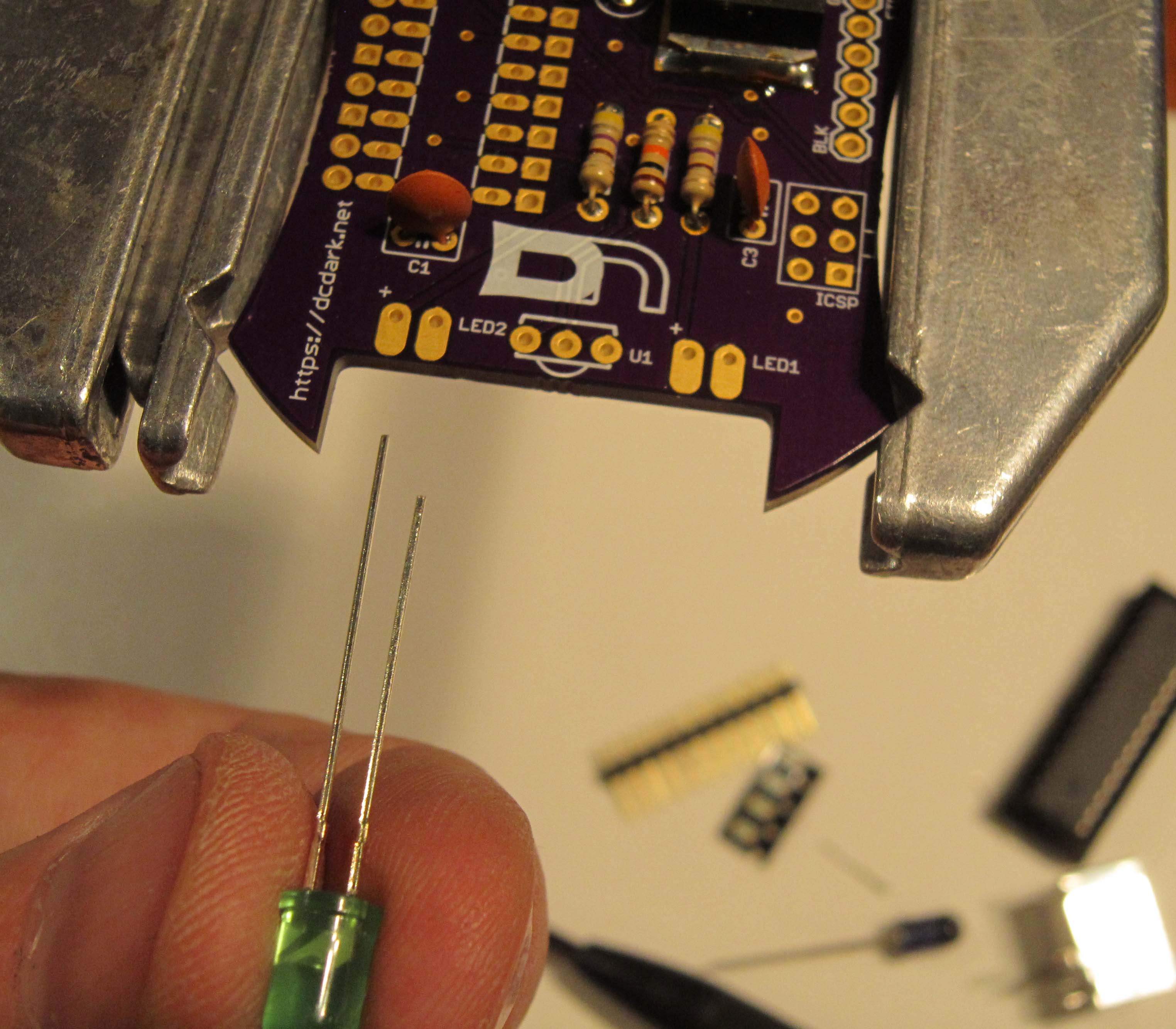
Bend the leads of the LED so that the case is flat pointing in the direction of the points on the board as shown.
There will be about 3mm of lead between the case of the LED and the bend.
Do not solder the LED so it is perpendicular to the board. This will be important later.
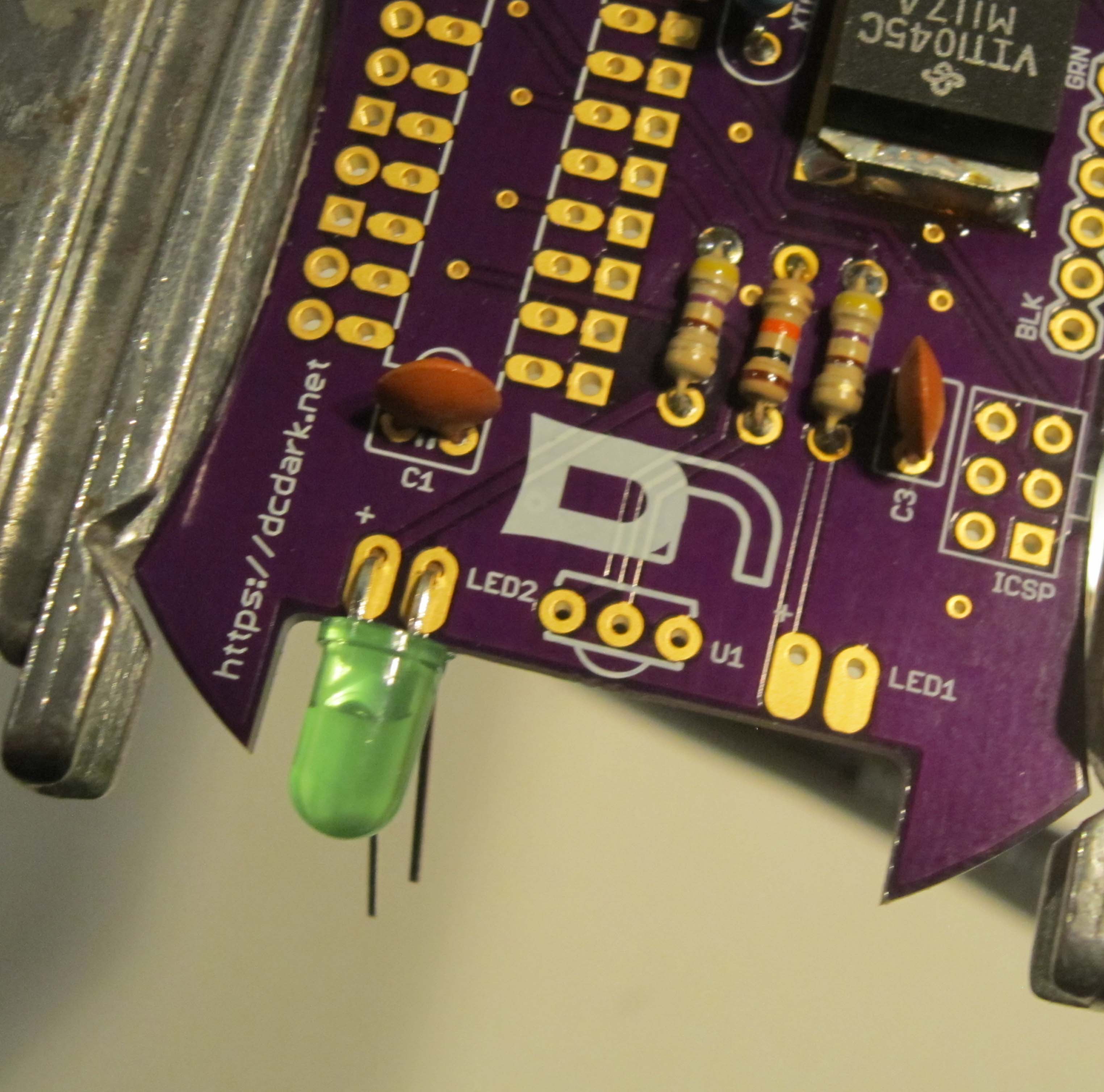
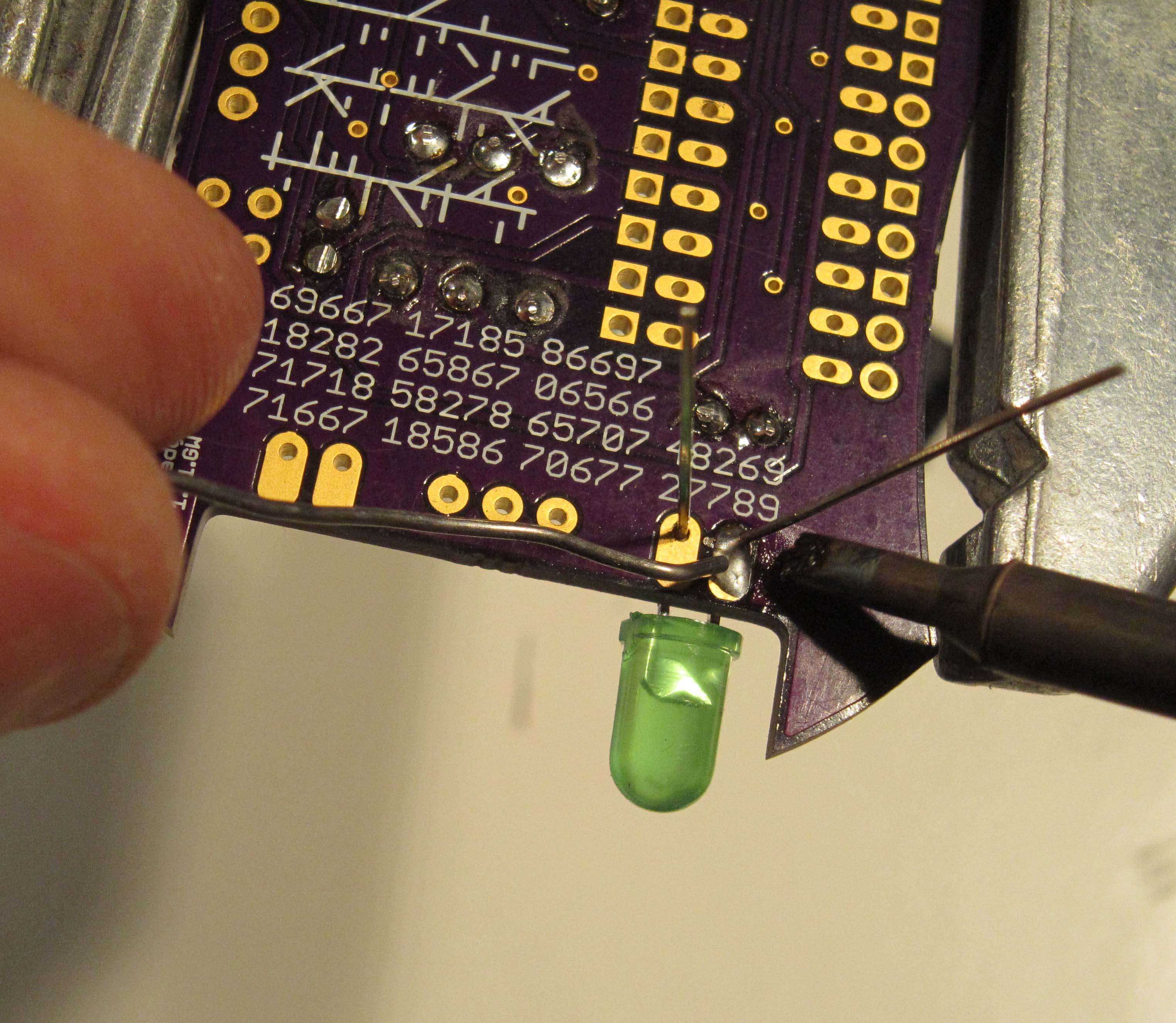
Solder the LED in place from the top side of the board.
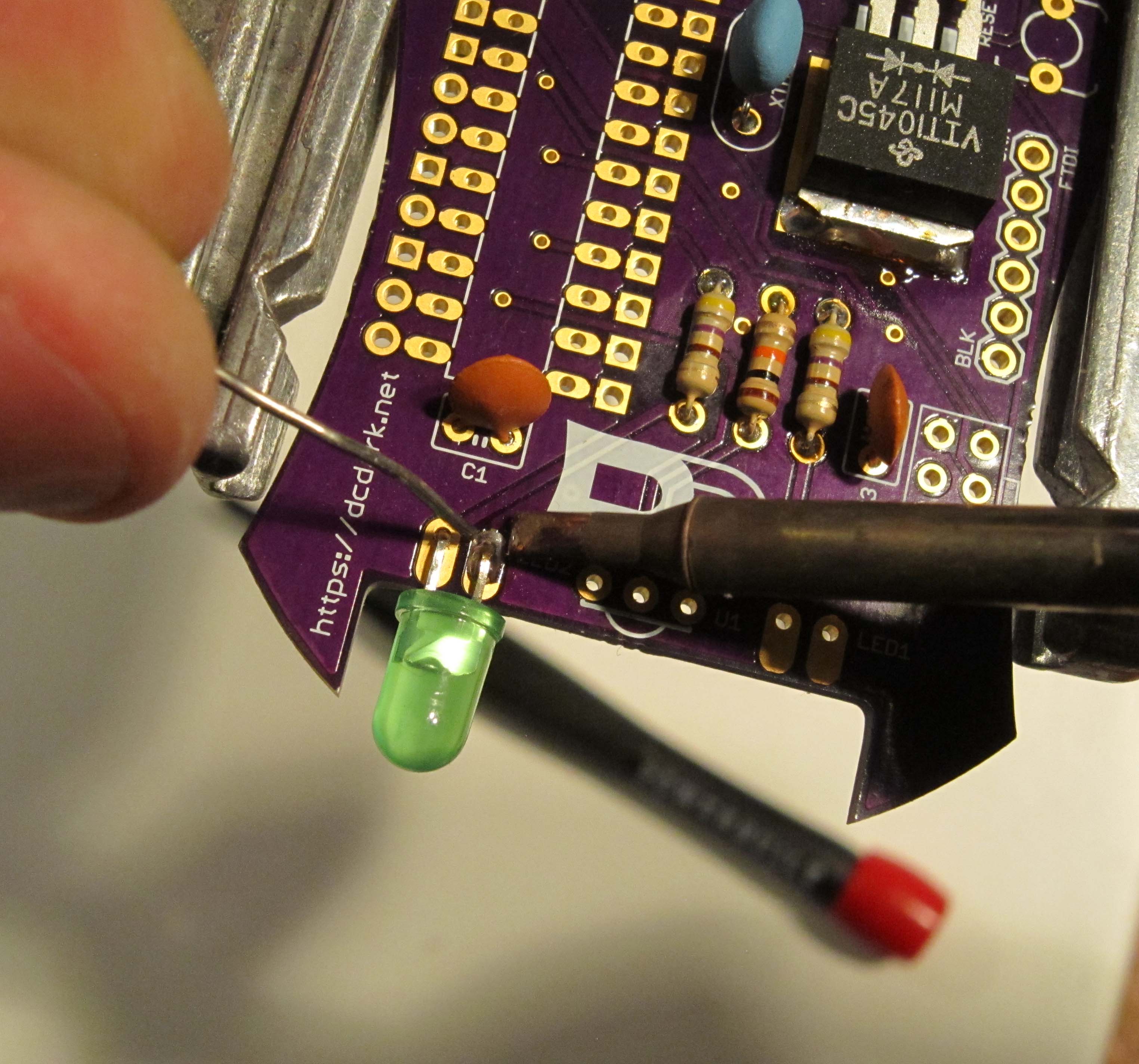
Next solder the leads of the LED on the underside of the board.
The next part is the infrared LED, at LED1. This enables the badges to communicate with one another wirelessly. The long lead is positive.
Again, install the LED so that it is laying flat as shown. Soldering from the top of the board first, and then the underside of the board.
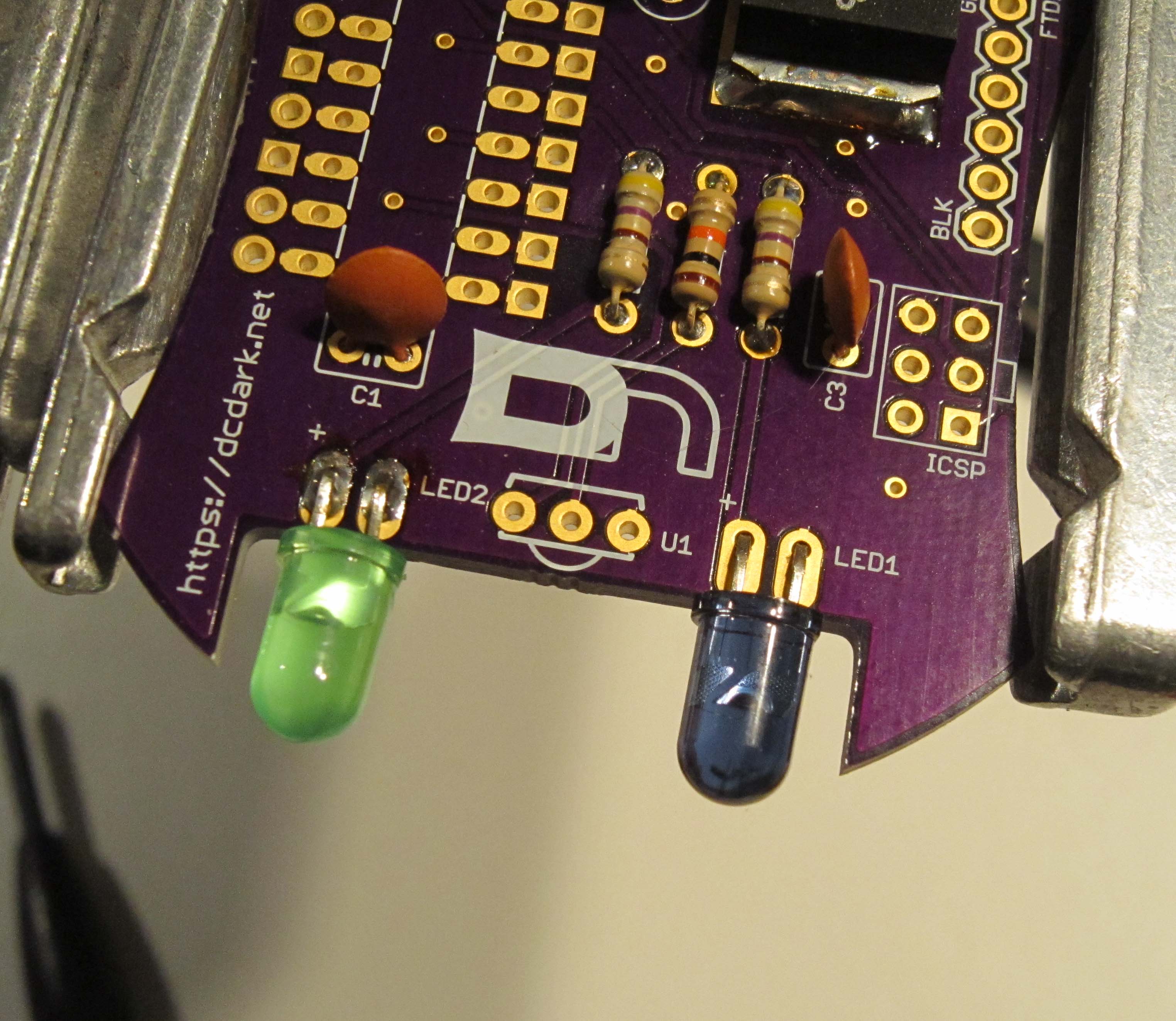
Finally trim the leads.
Now we add in the infrared receiver module. This component is polarized, and is installed in U1, so the dome is pointing toward the bottom of the badge.
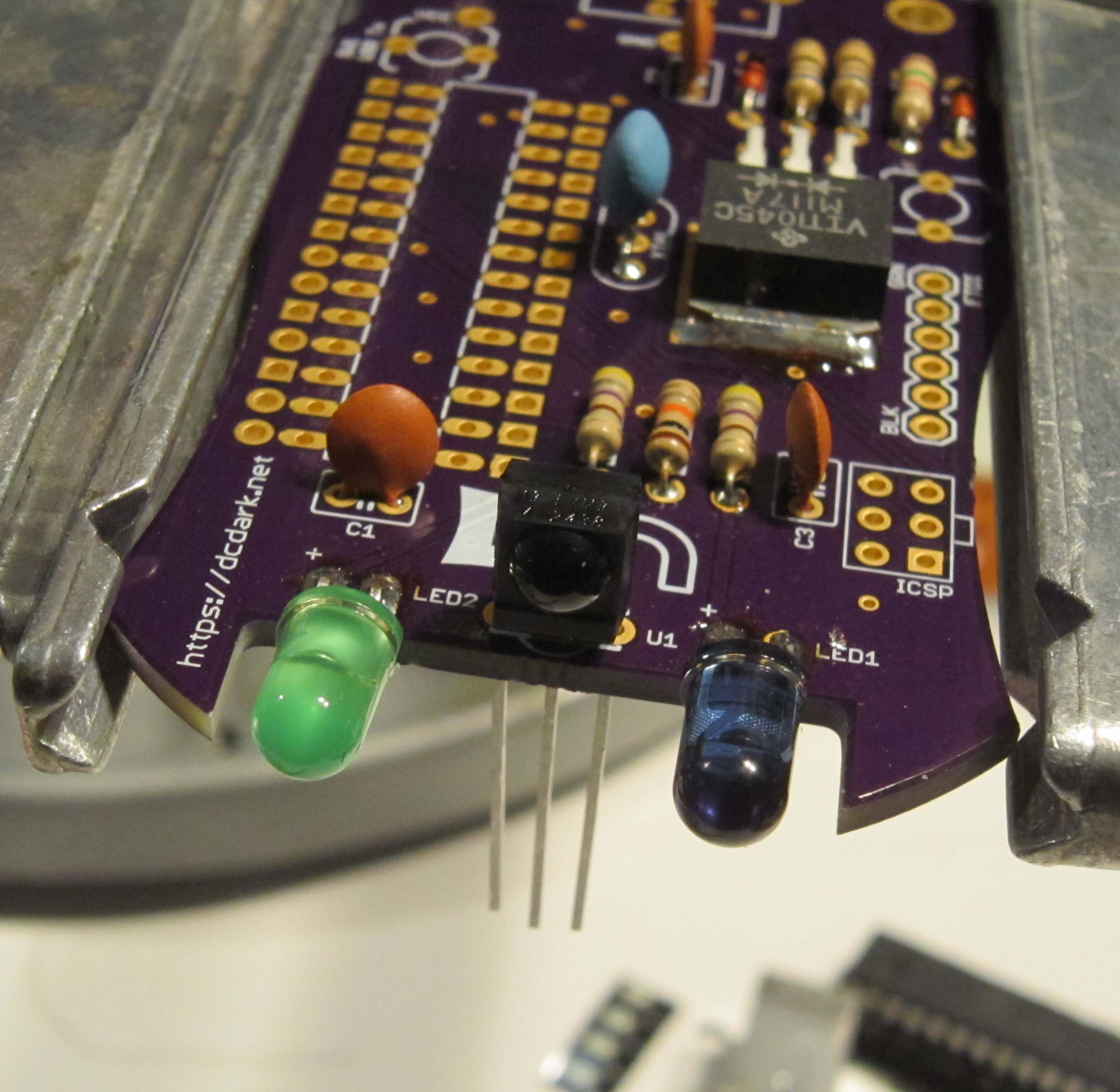
Solder and trim the leads.
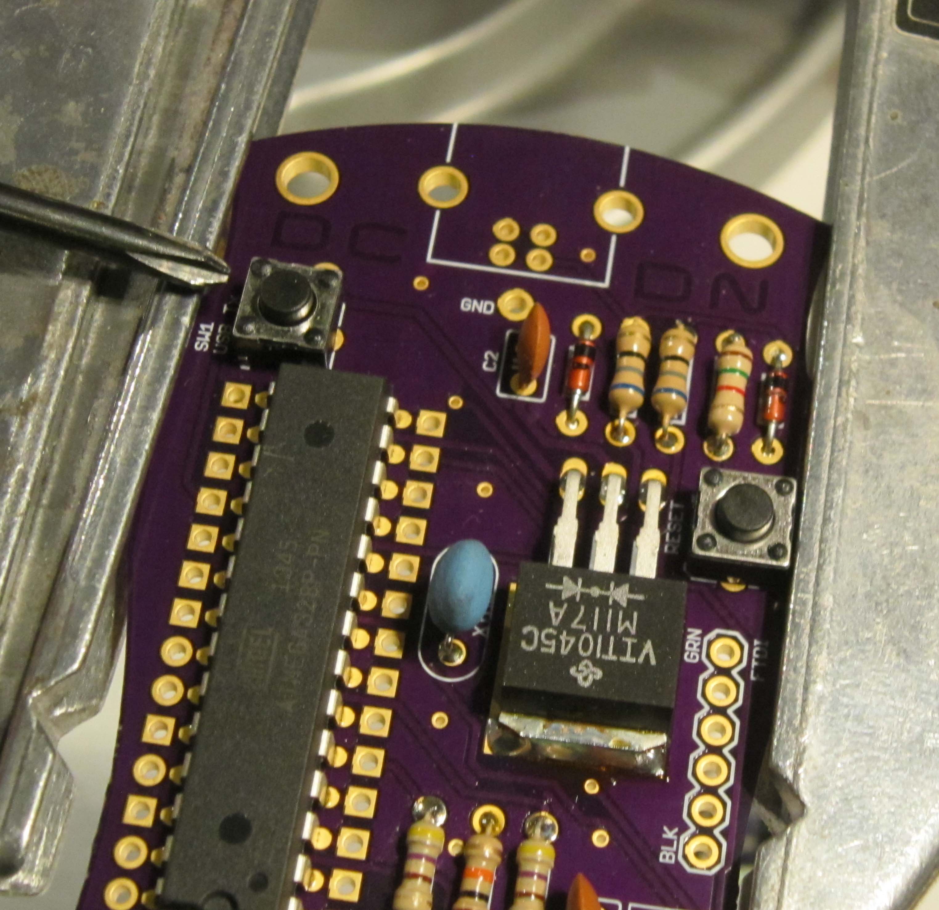
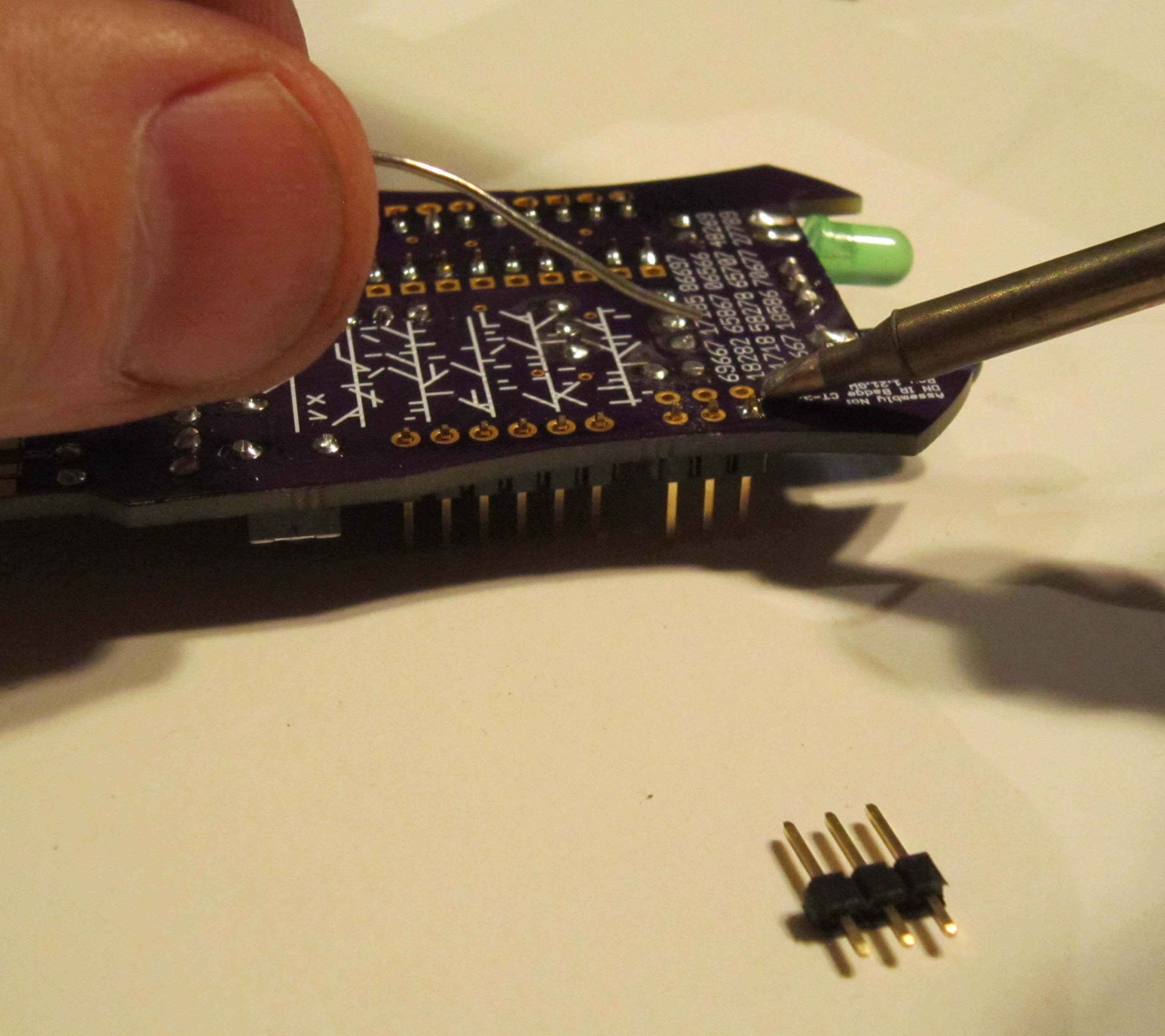
Now time to add the brains of the board. This component is polarized, and difficult to desolder if installed incorrectly. The polarity of the part is indicated by a notch on one end of the chip. This corresponds to a notch depicted on the PCB silk screen.
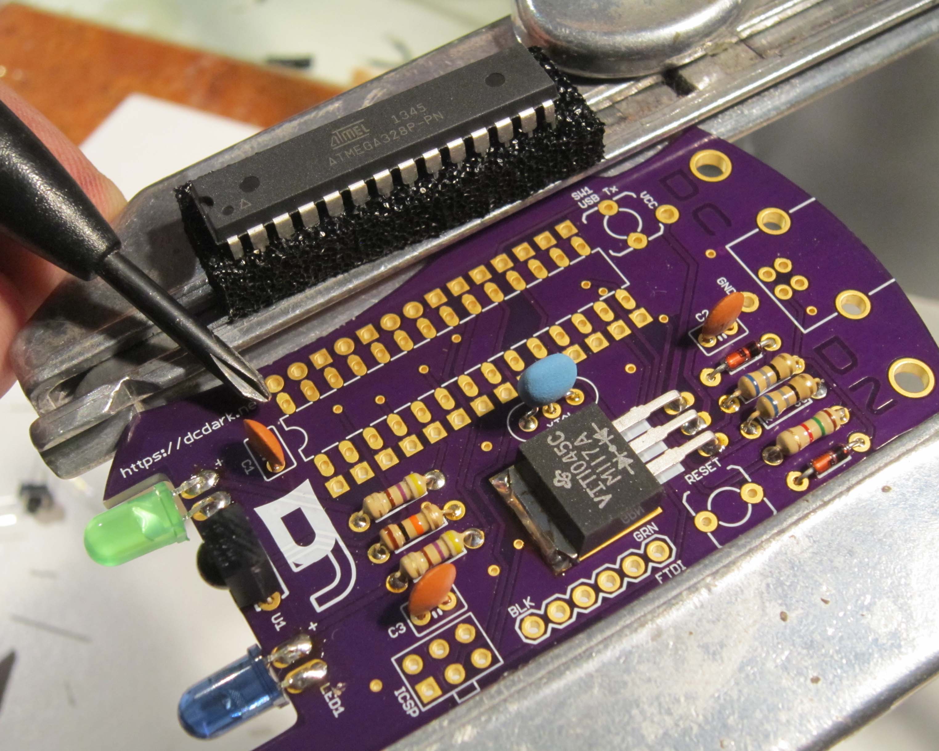
From the factory the leads on the chip are splayed slightly outward, and must bend the pins a little to make them fit in the PCB. The easiest method is to rock the pins against the flat surface of a table top to carefully bend the pins. (The image shows a smaller chip, but the idea is the same).
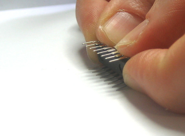
Once the pins are parallel, install into the PCB as shown.
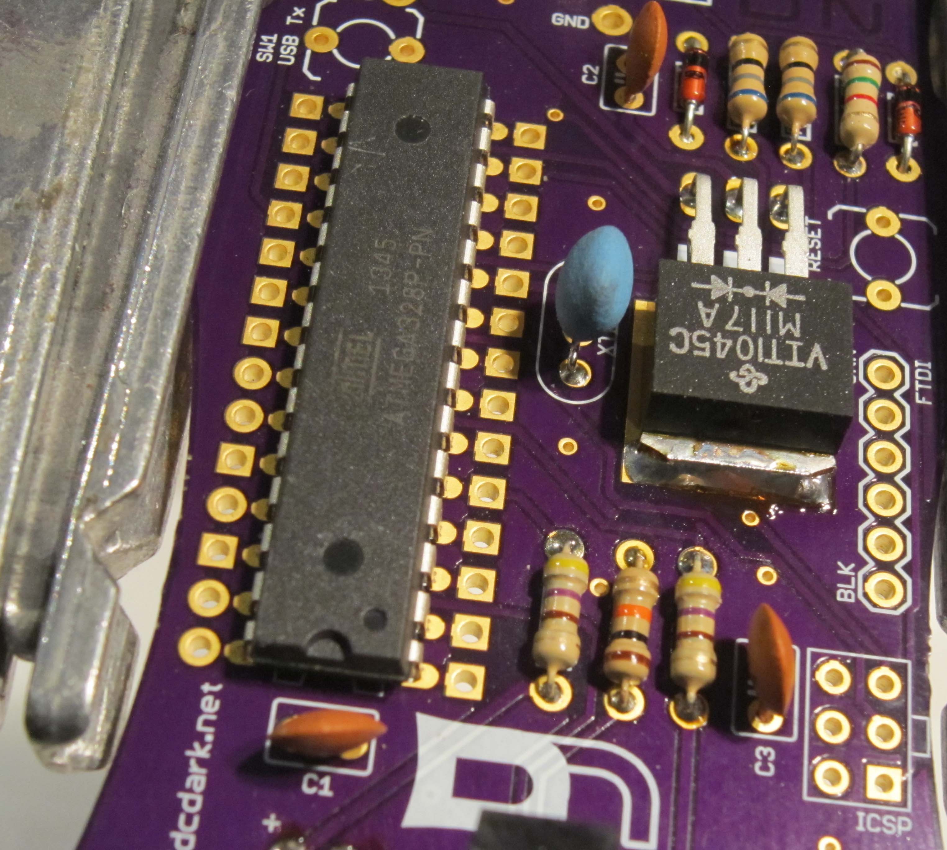
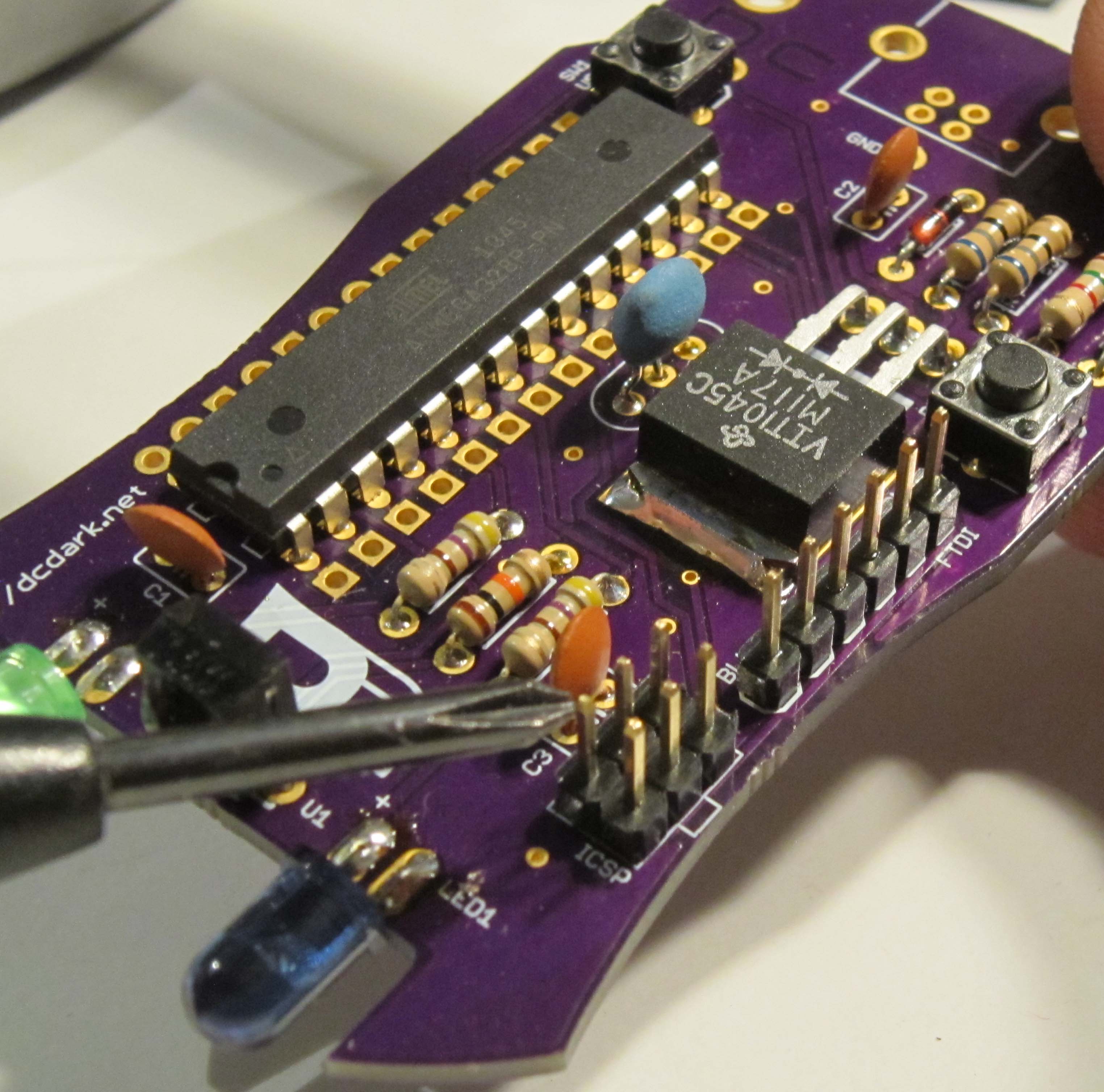
Solder the chip in place. I start by soldering opposing corners to keep the chip in place.
Before proceeding, double check that your chip is installed in the correct orientation and flush with the PCB.
Solder the remaining pins. There is no need to trim the leads.
Next install the two microswitches, SW1 and Reset. These components are not polarized, and may be installed in either direction.
The USB button, when pressed will have your badge emulate a keyboard device.
The reset button resets the badge, and is also used to cycle between modes.
Solder and trim the leads.
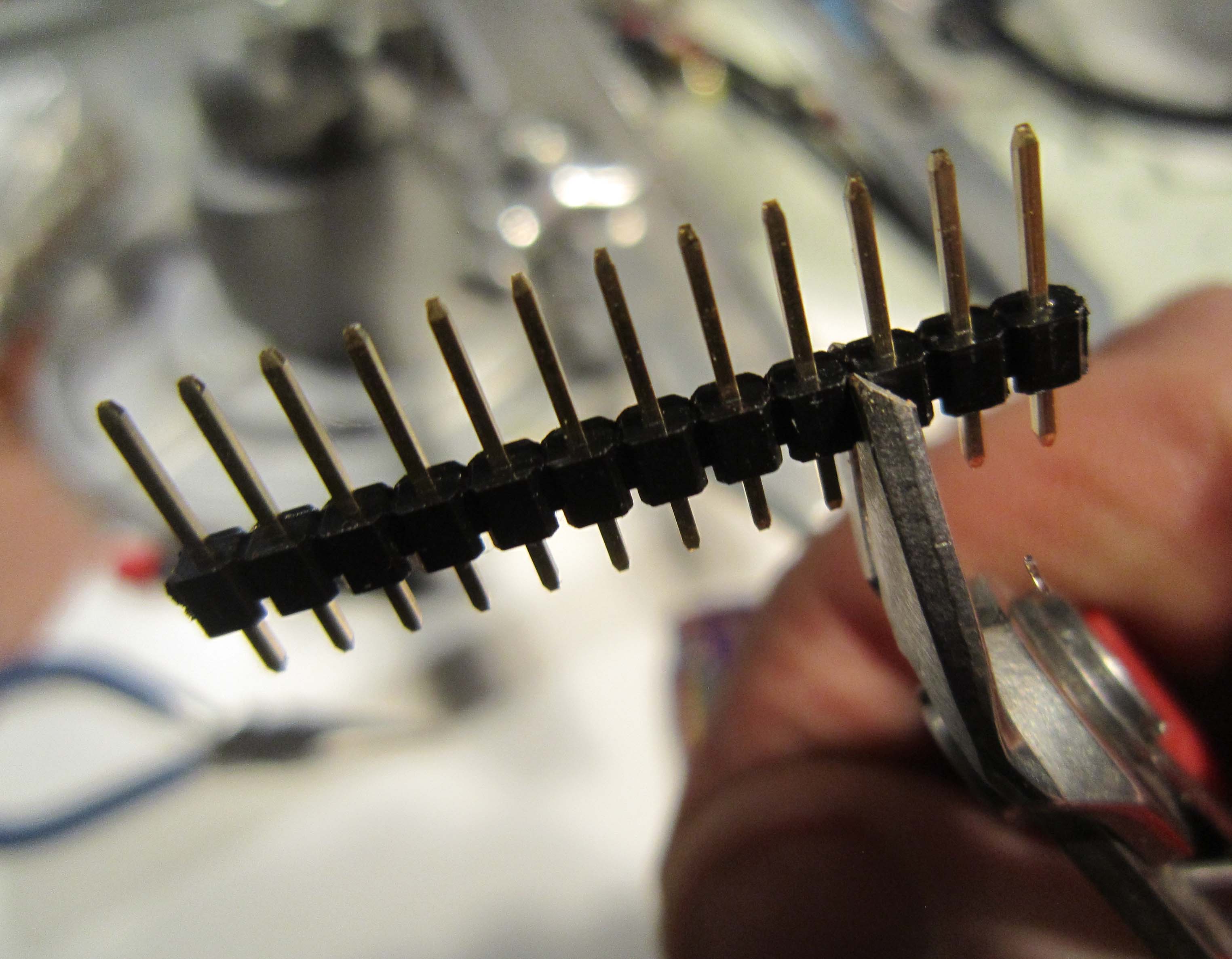
Incuded in the kit is a 12 position male header. This will be cut to make a six position header, and two three position headers.
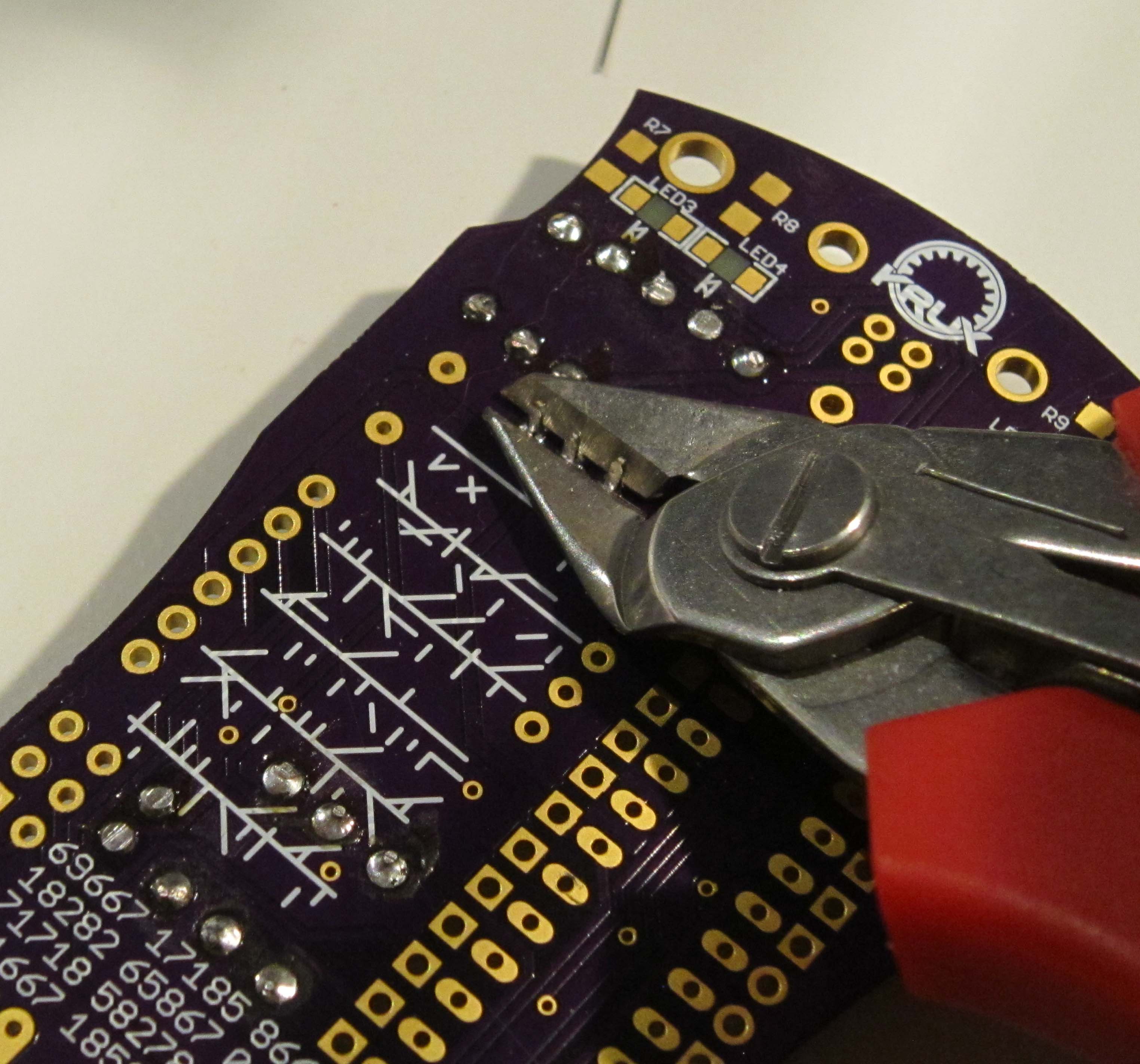
Using your flush cutters, trim three pins off the header.
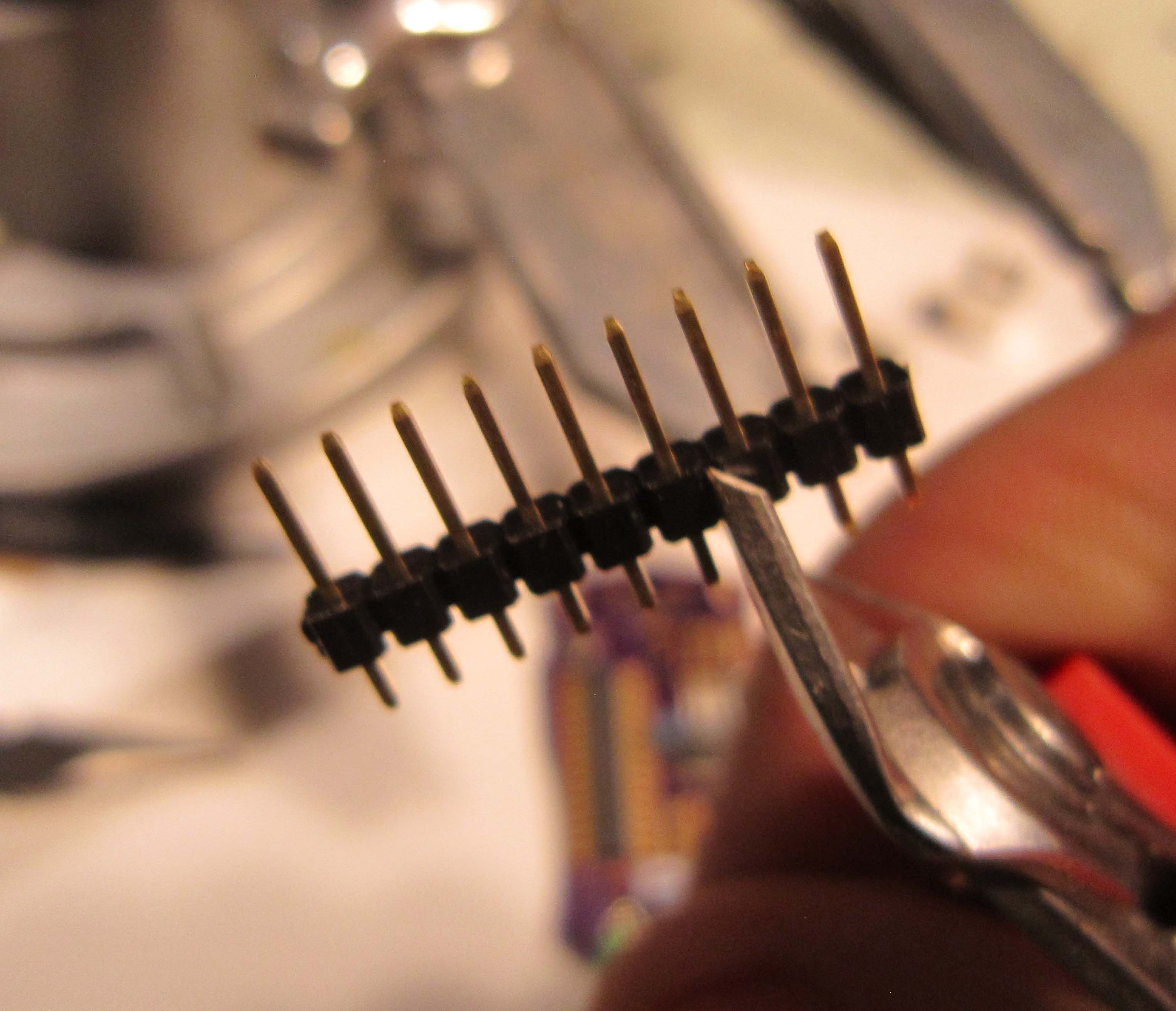
Next cut off three more pins.
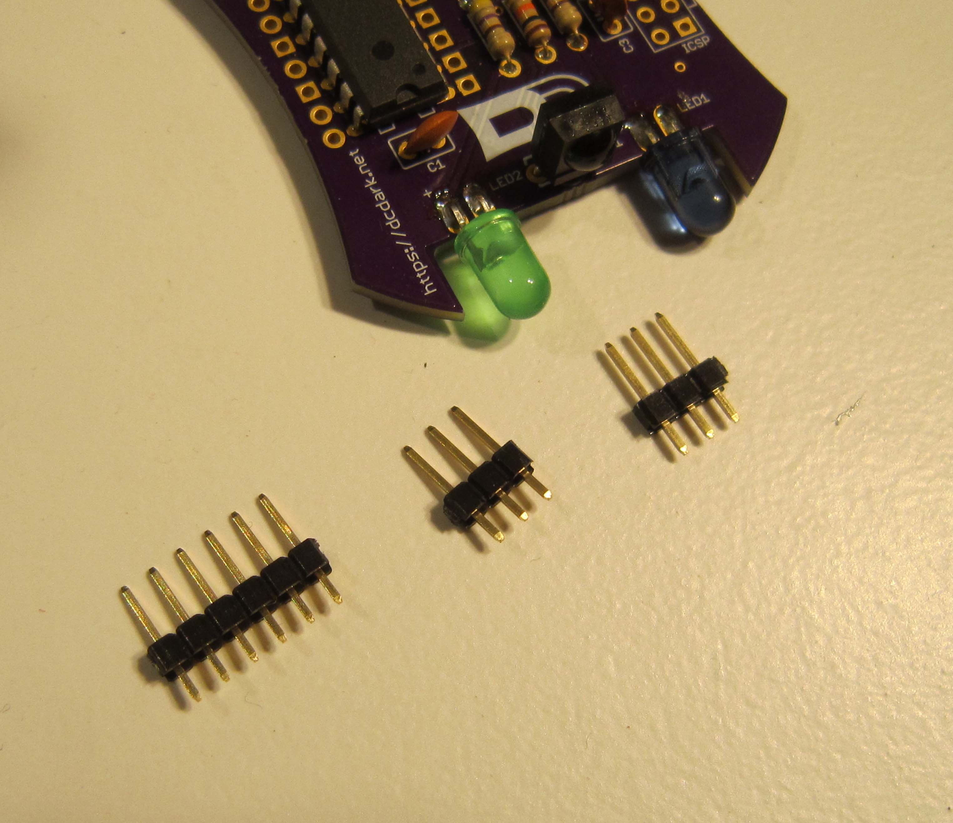
You should be left with a set of six and two sets of threee.
Install the six pin, and one of the three pin headers, using the board to hold them in place. You may have to prop the opposite side of the board on the handle of your cutters, to ensure enough force is in place to hold the pins.
Solder one pin on each and check the alignment. Correct if needed and solder the remaining pins.
Next solder in the remaining three pin header.
The leads of the programming headers do not need to be trimmed.
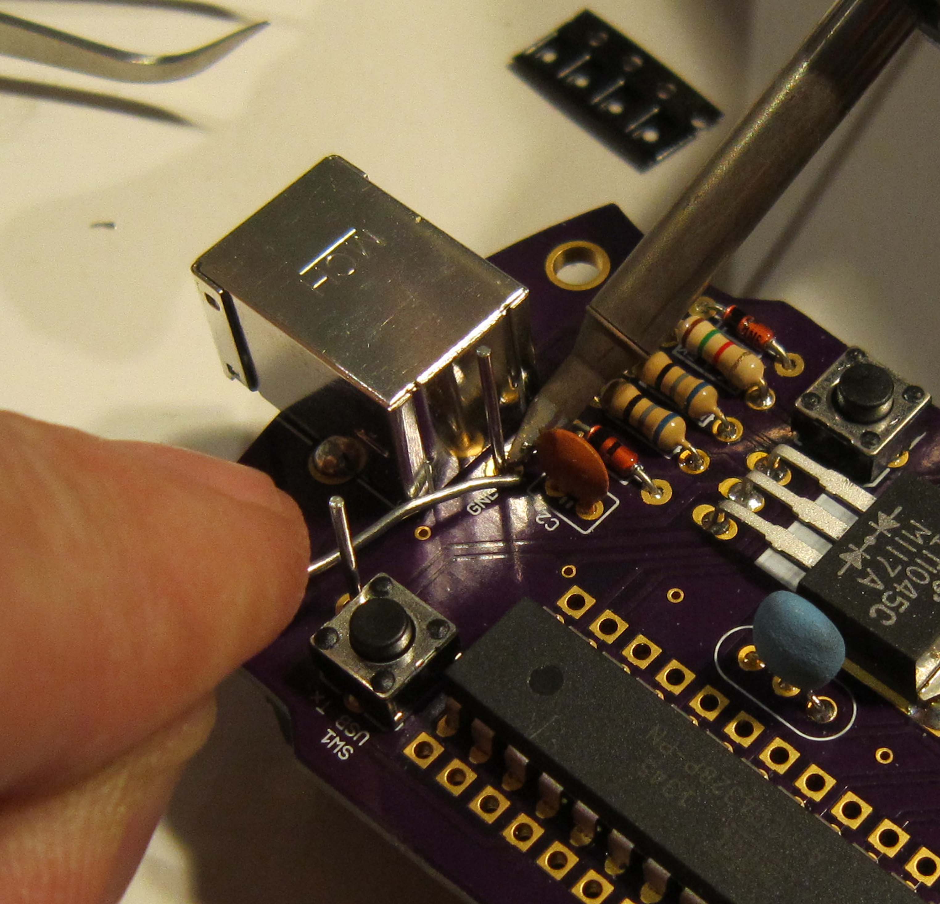
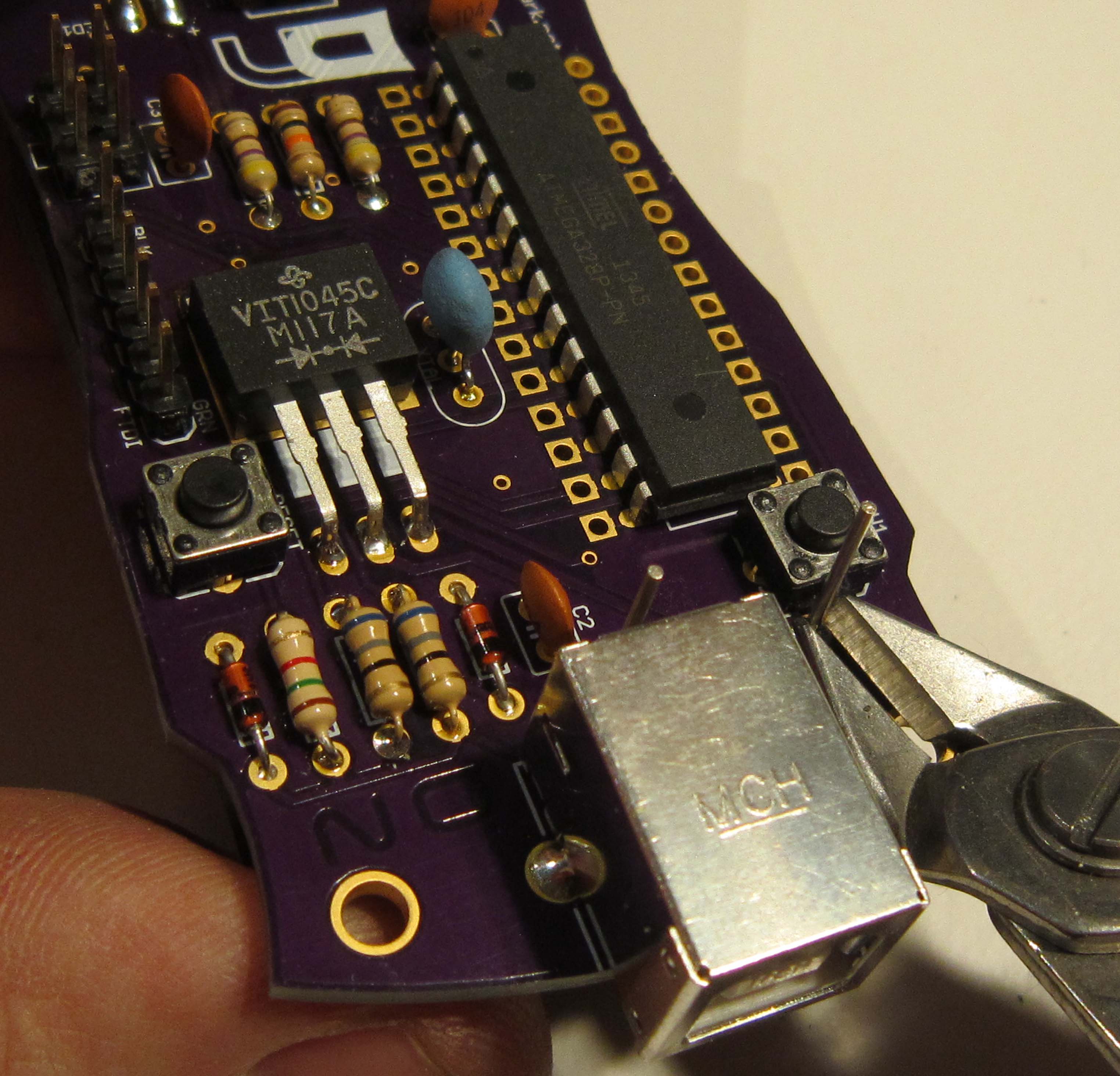
Install the USB connector as shown
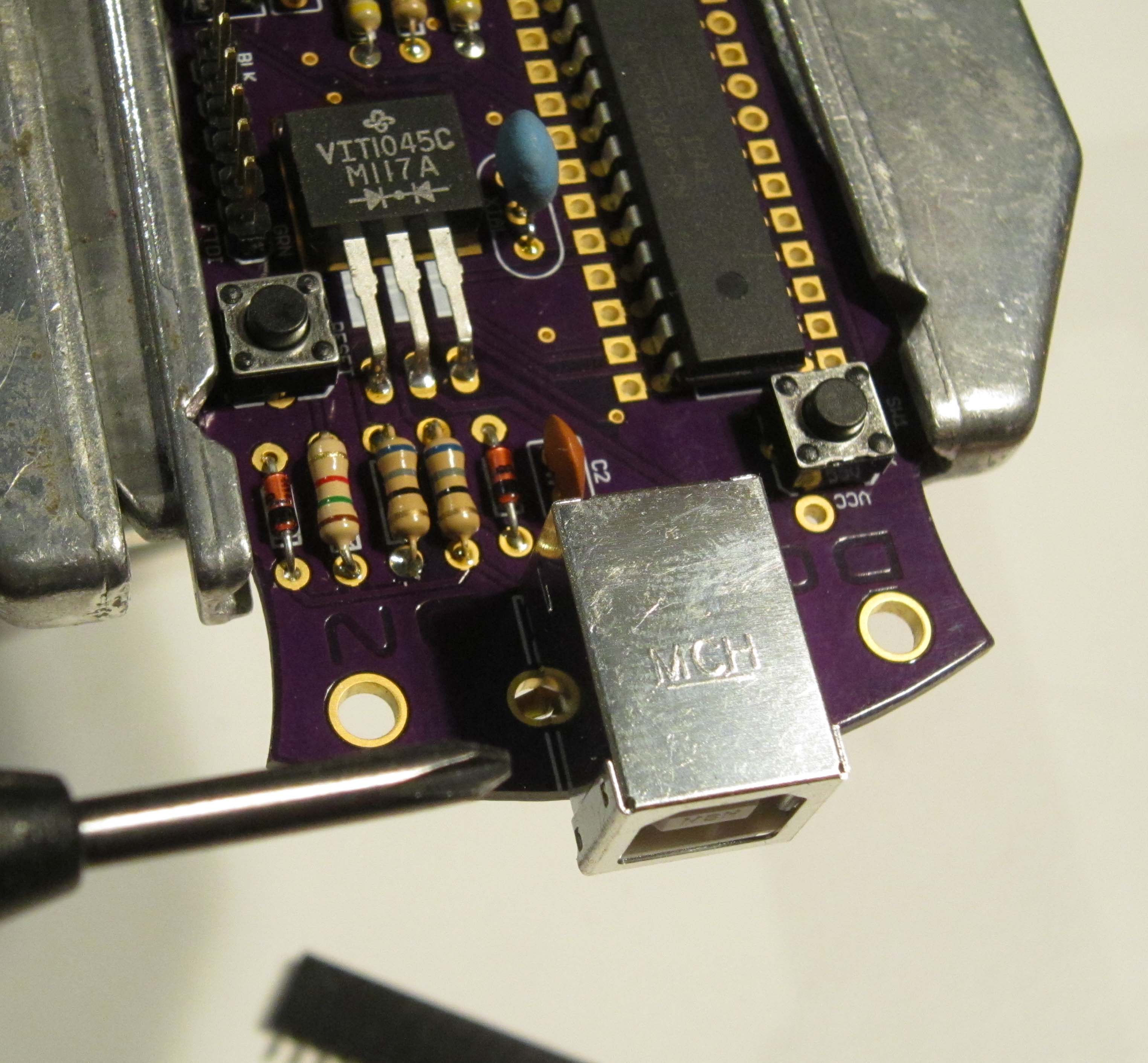
The two tabs which mount the connector to the board will require enough solder to fill the hole in order to structurally keep the connector
in place when plugging in the cable.
Included in the kit this year are the SMD parts to backlight the DC DN letters. The LEDs are soldered in place so they shine through the PCB substrate to illuminate the letters when viewed from the front of the board.
While tricky, surface mount soldering can be done easily using the following techniques.
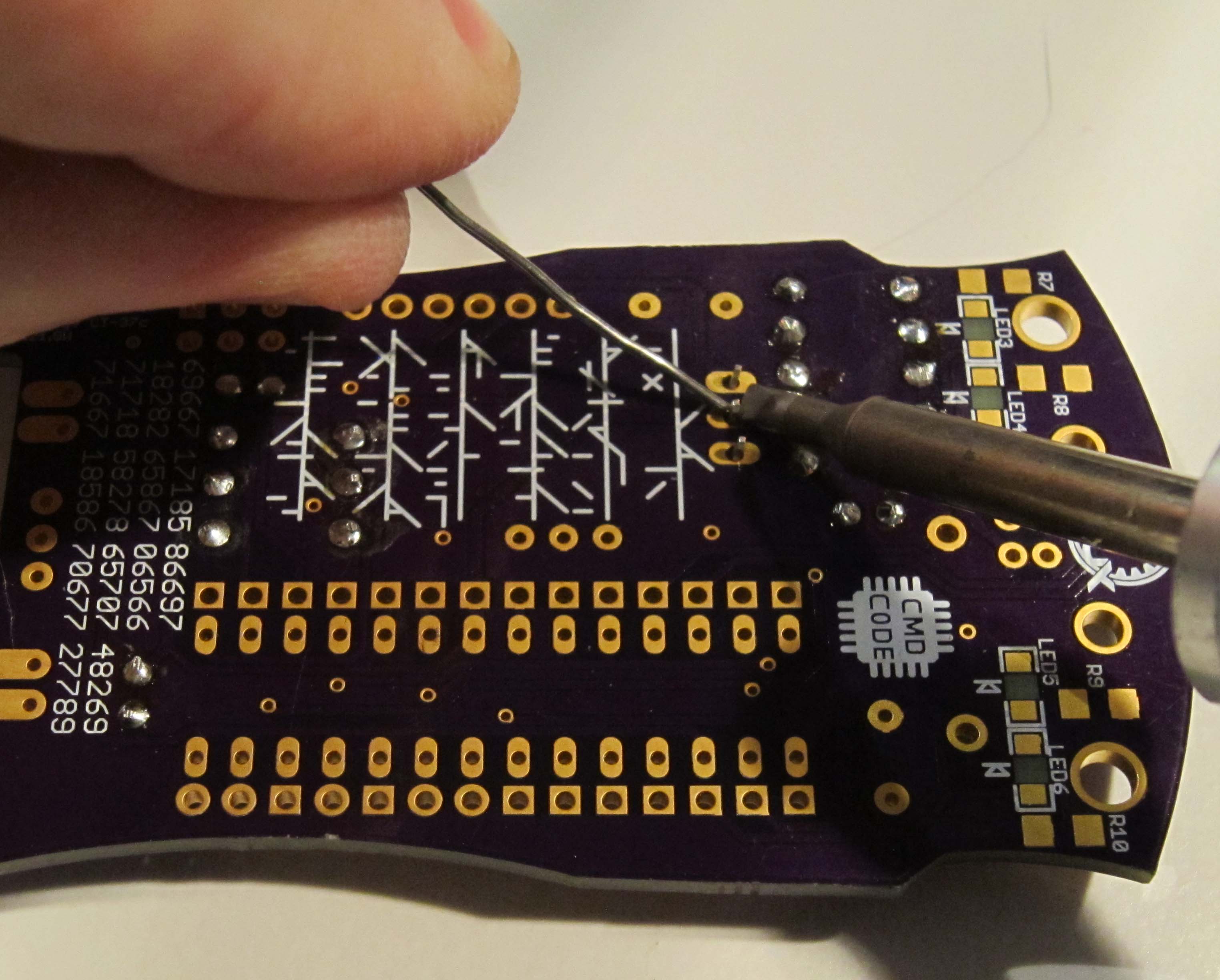
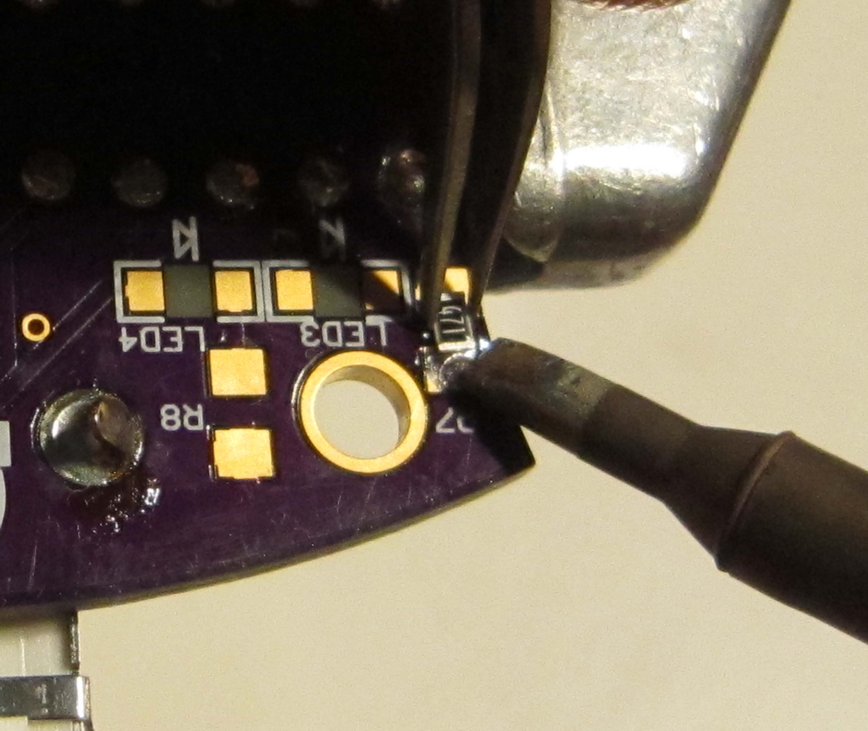
First we will install the resistor R7. Apply solder to one of the pads.
Using tweezers, pick up one of the resistors and guide it in place while heating the solder on the one pad, then remove the soldering iron while continuing to hold the part in place.
If needed the part can be adjusted by melting the solder and moving it carefully with the tweezers. It often helps to use magnification for this step.
Next solder the second pad of the resistor.
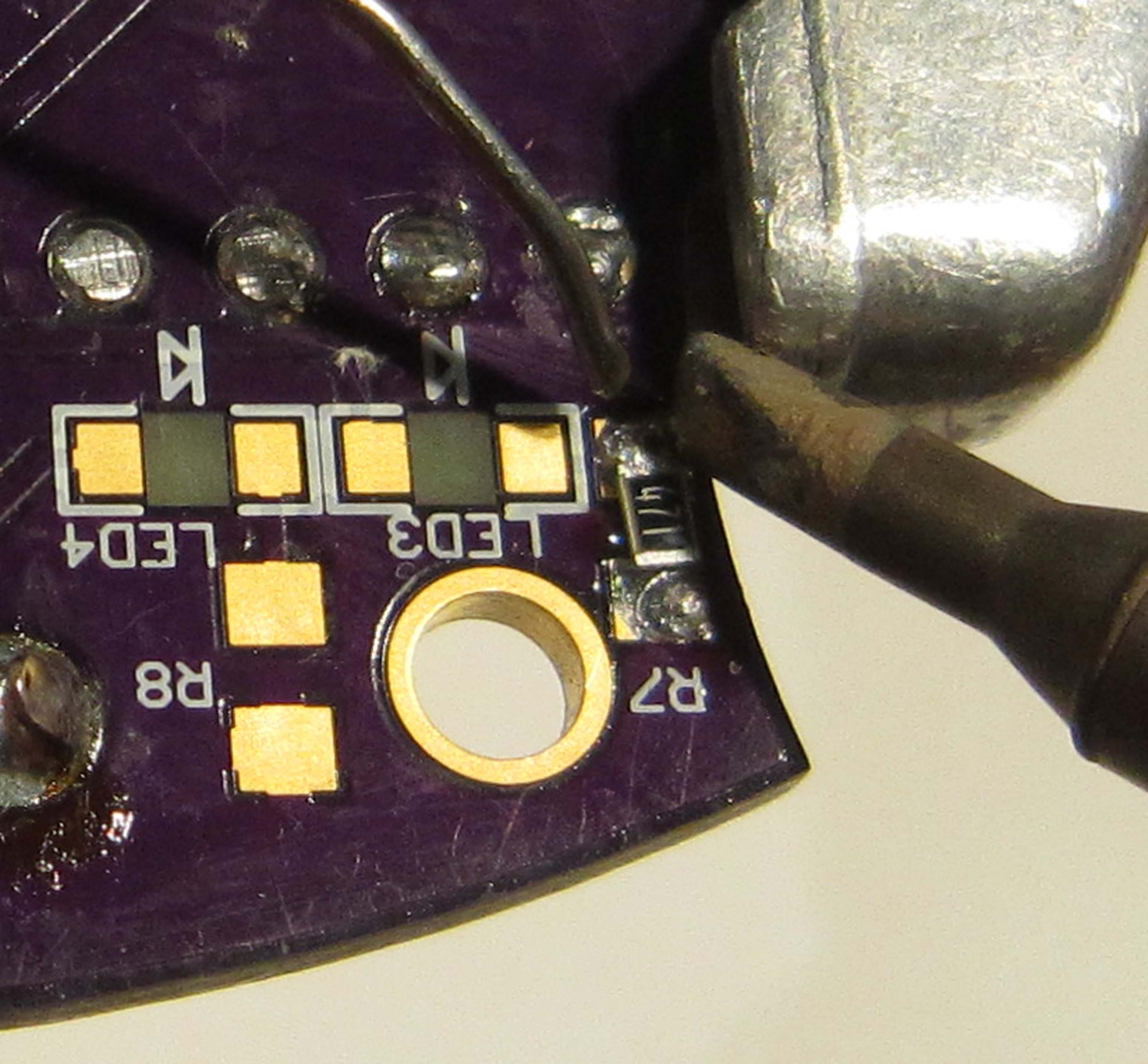
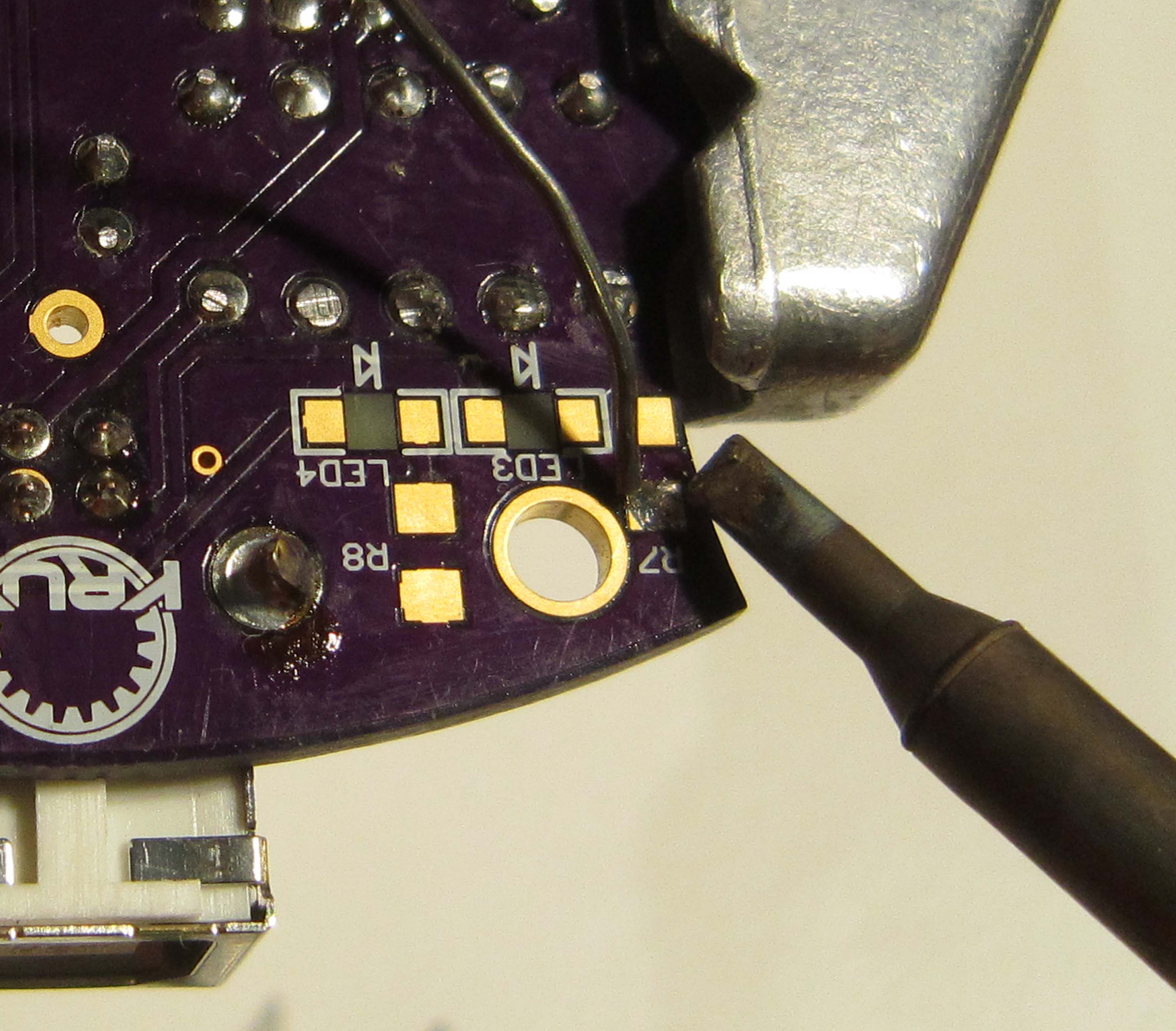
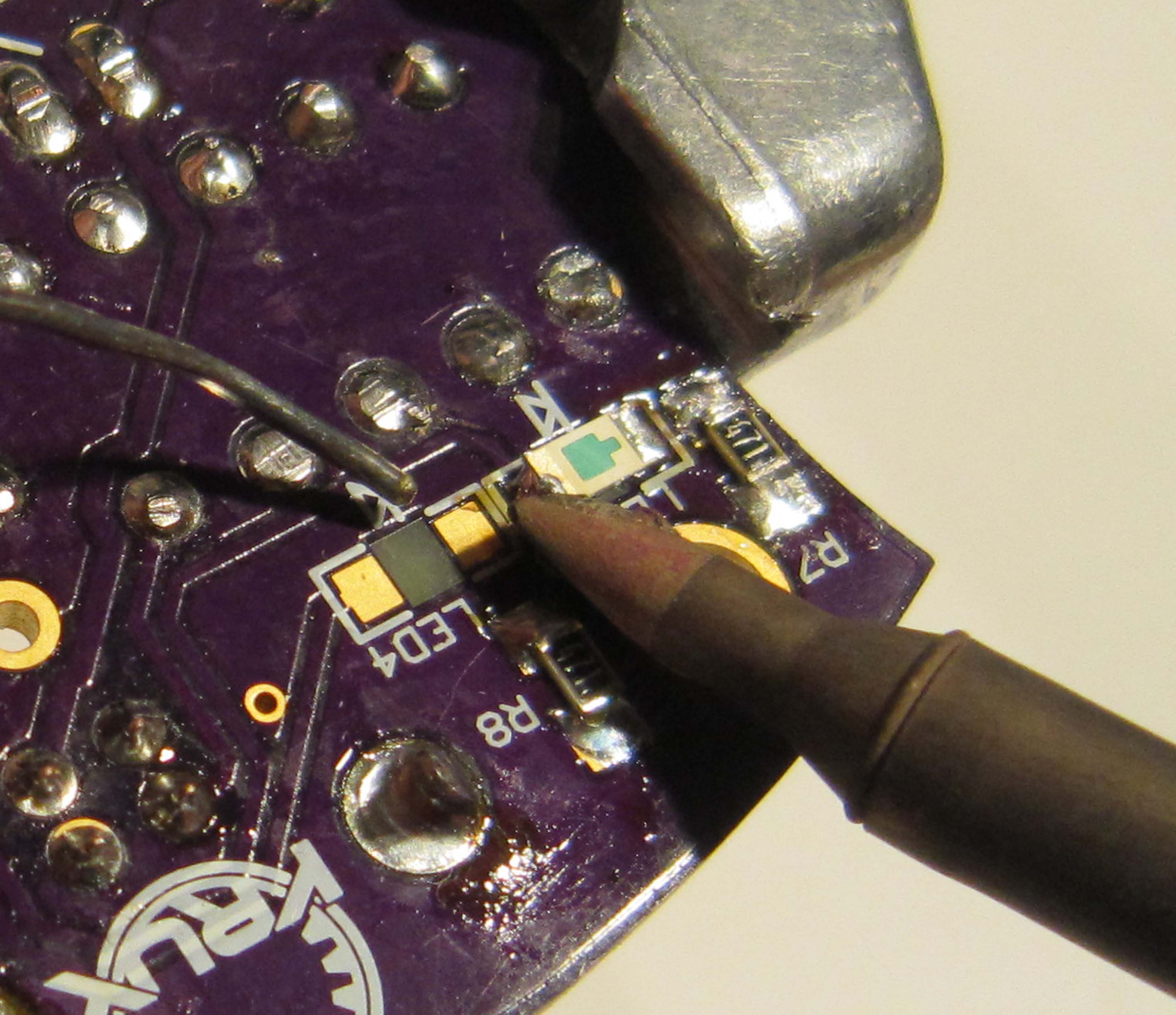
Next we will solder in the LED3. Like all diodes, SMD LEDs are polarized. The PCB has the symbol which indicates the Anode and Cathode.

Add solder to one pad, as we did with the resistor.
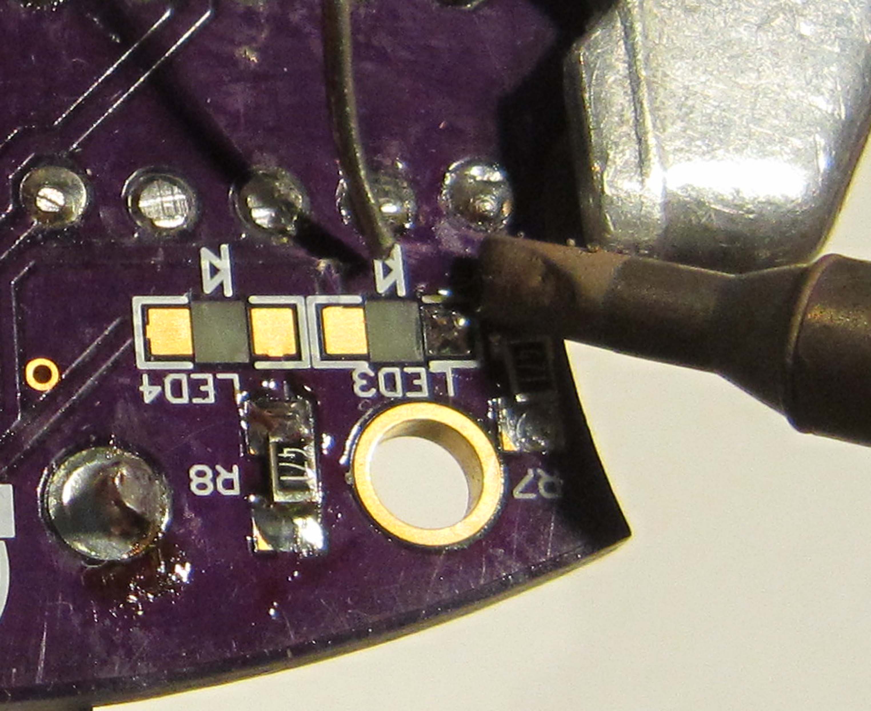
The LED has an indicator on the underside which shows the polarity, with and triangle or arrow pointing toward the Cathode or negative.
Heat the solder, and then using tweezers guide the LED into place as shown. Conveniently, as we are installing these upside down, so that they shine through the PCB substrate, you can see the marker that shows their polarization while soldering.
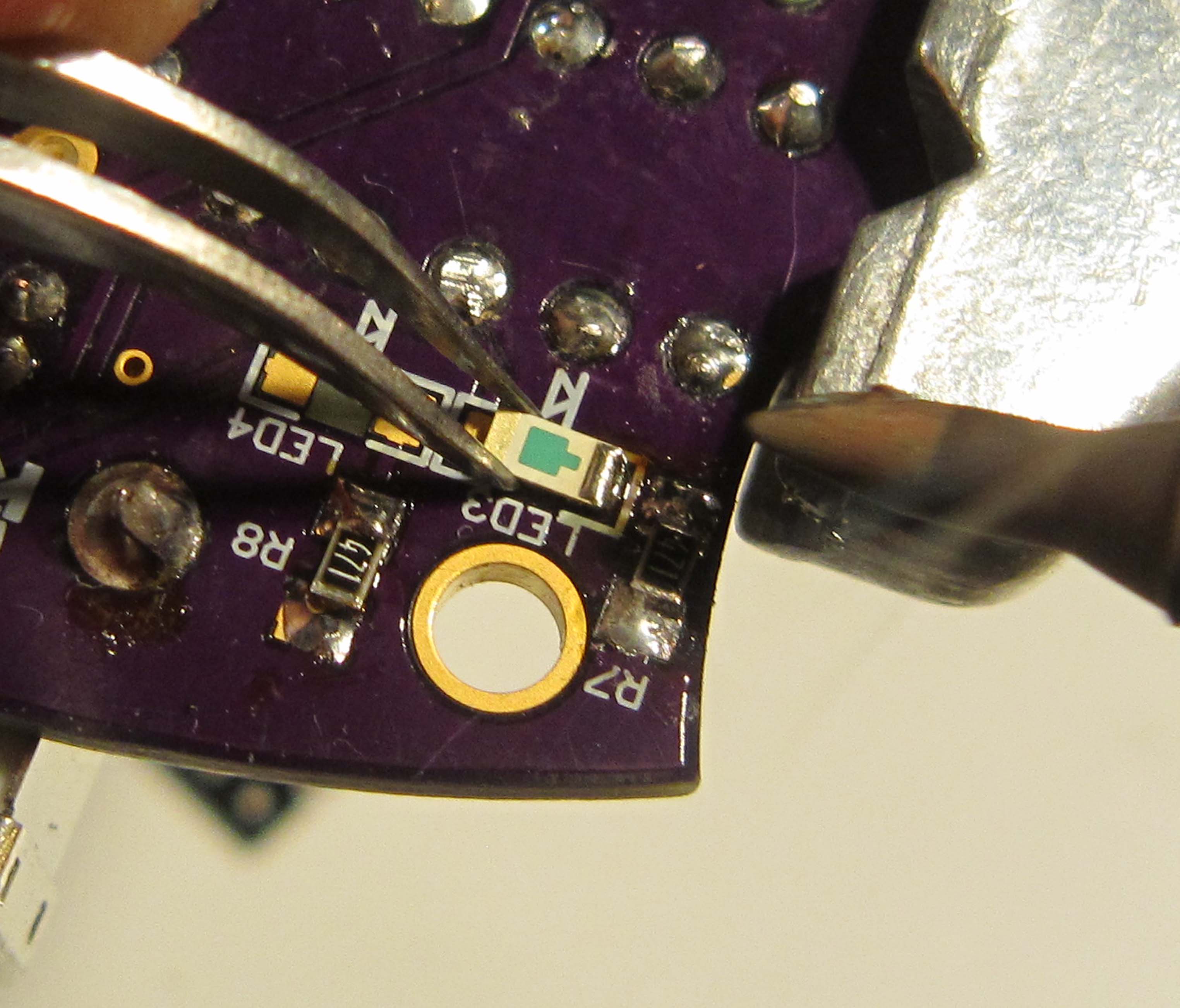
Again, now add solder to the remaining pad.
And finally repeat for the remaining resistors and LEDs.
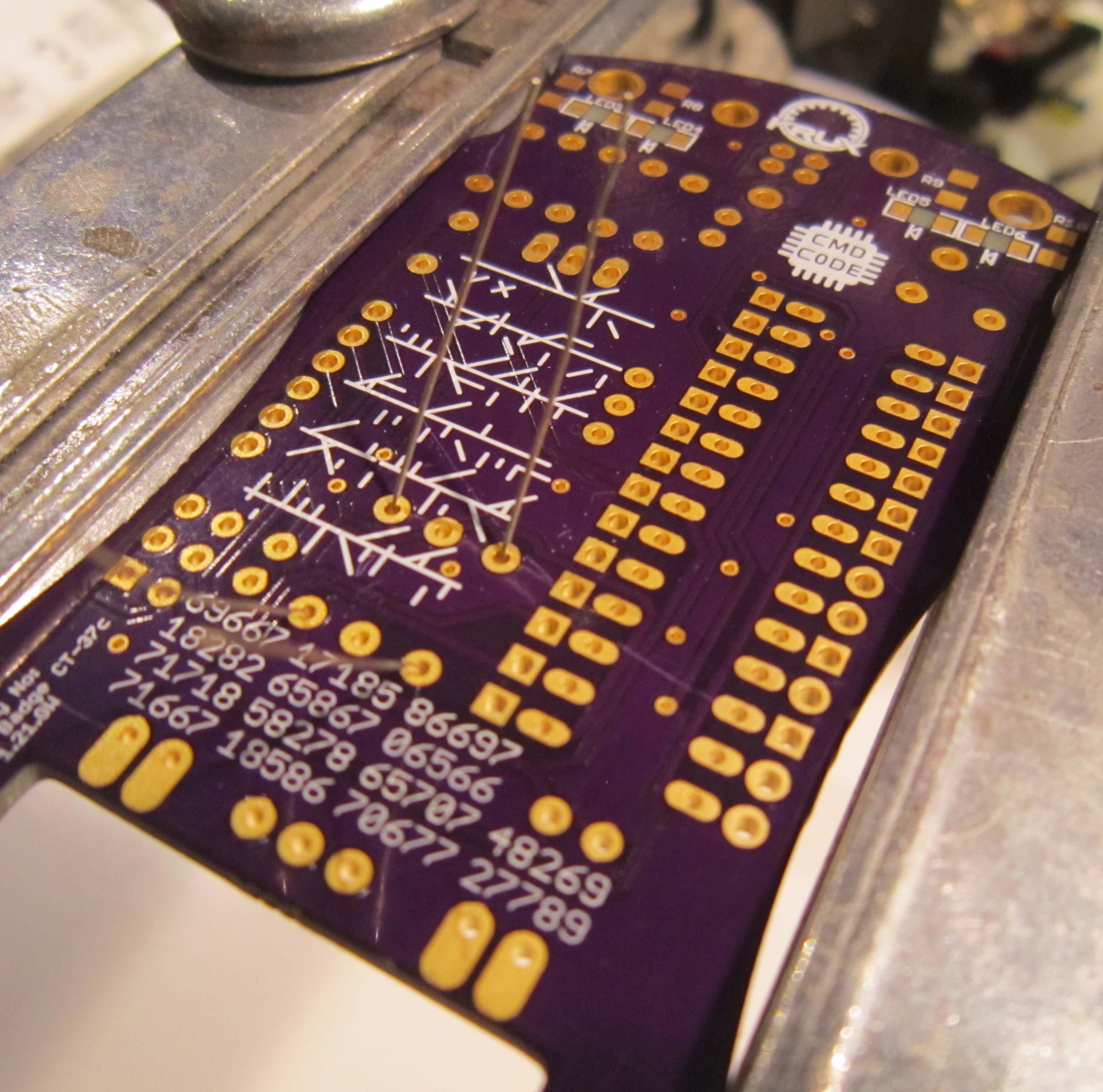
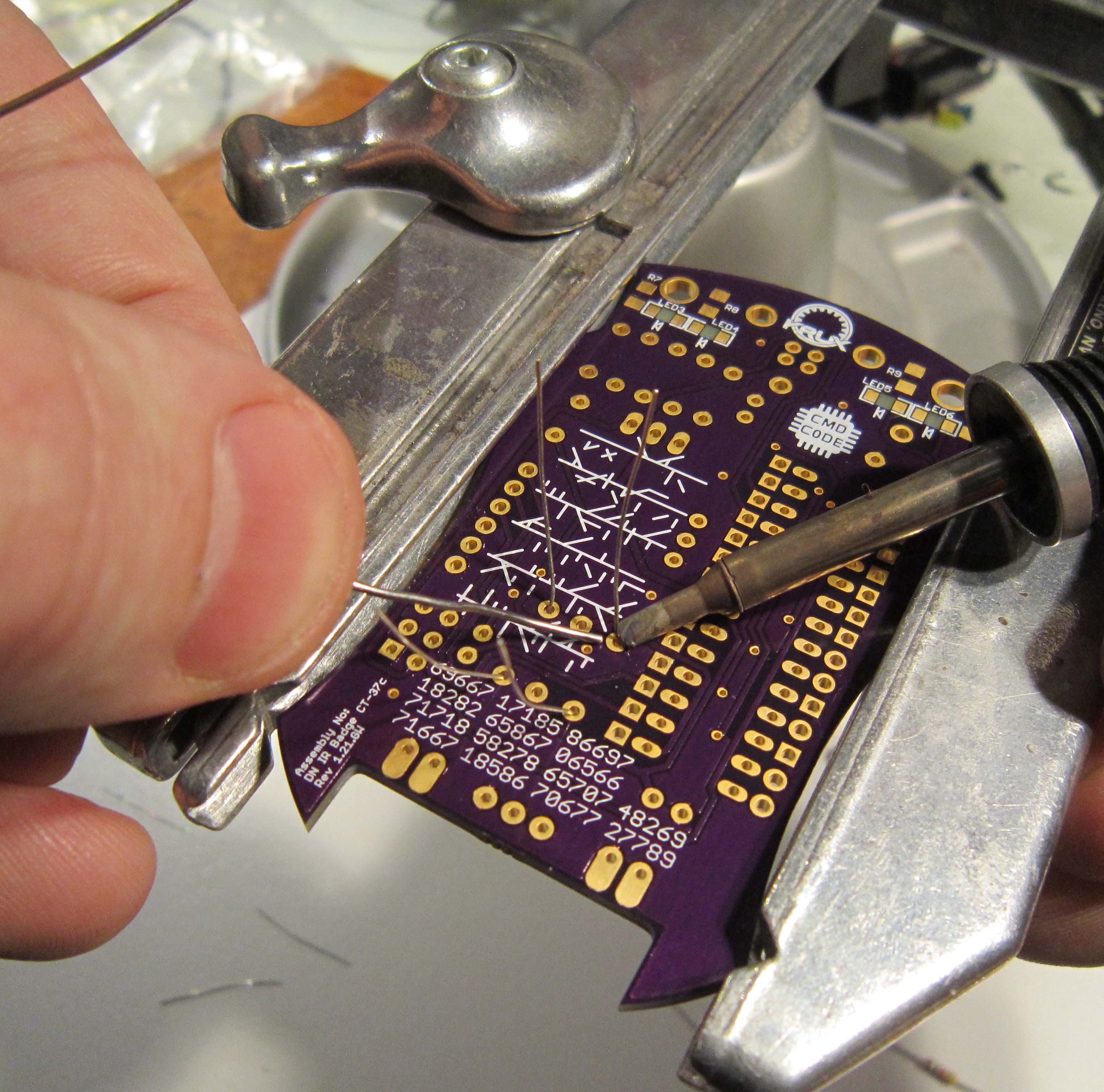
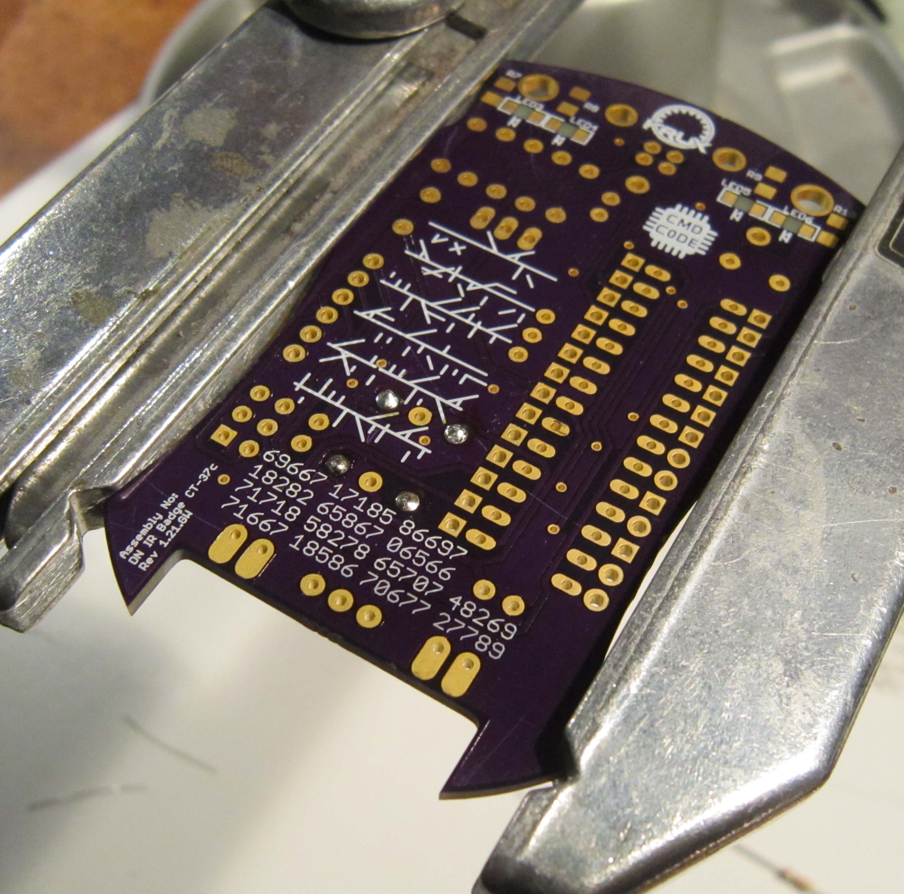
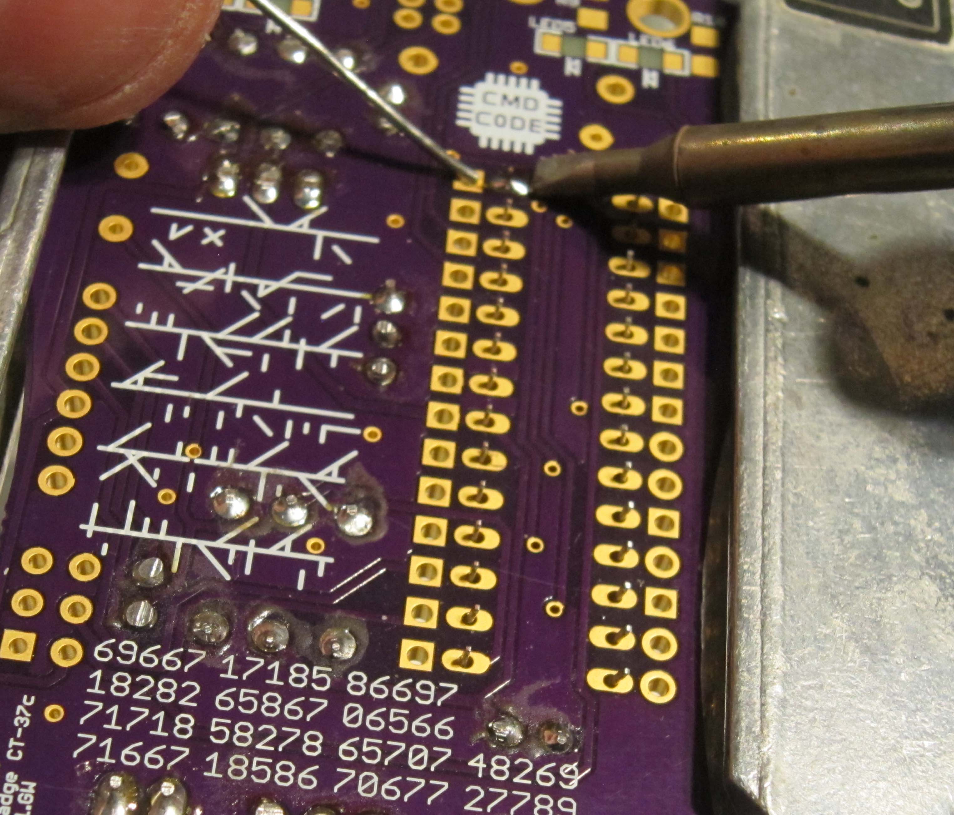
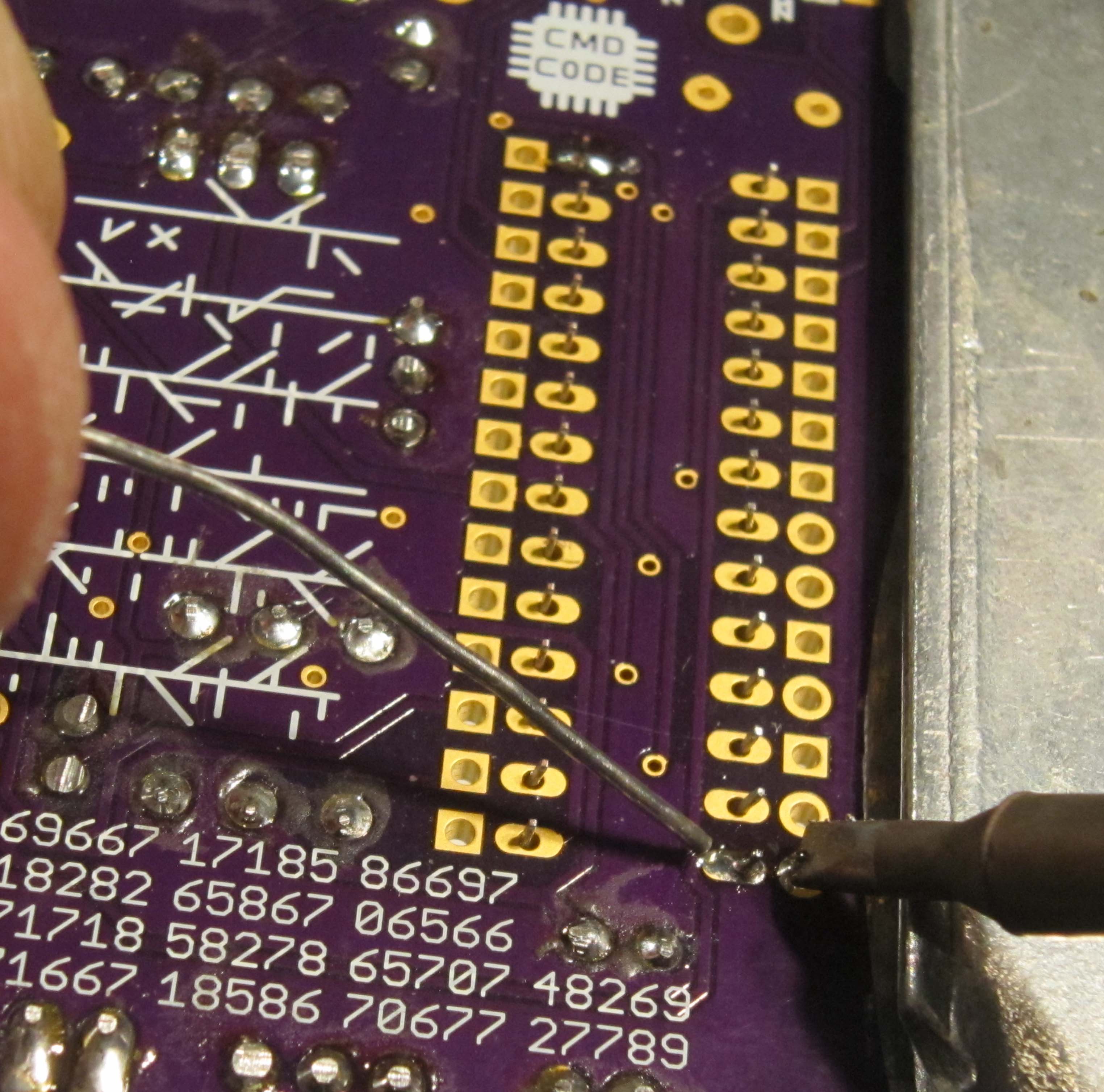
Now would be the time where you would clean off the solder resin from the underside of your board using some denatured alcohol. As well as taking a moment to check your work.
You may even want to take a picture of the underside of your board, since by now, no doubt you have noticed the silk screen
has some curious looking numbers and lines.
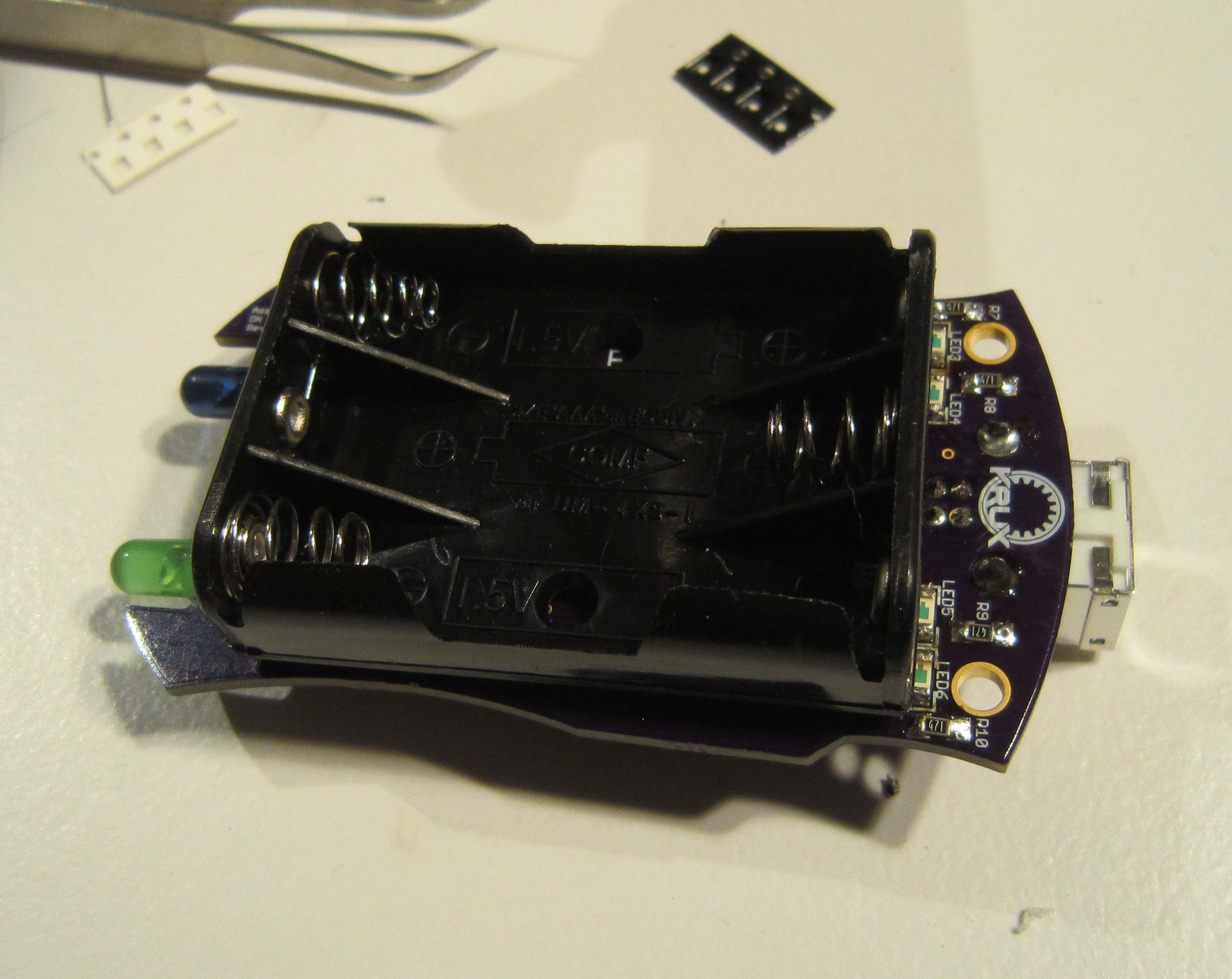
Finally we are ready to add the battery holder.
The battery holder will be flush with the bottom of the PCB. You will need to straigten the leads, and they were bent over during the kitting process so they could be placed in the bags.
If you want to test your board before soldering on the battery pack, you can apply power via the USB connector.
Solder the leads from the top side of the board.
Trim the leads.
And finally you are ready to install the batteries.
Once the board powers up the LEDs should start flashing. Cycle through various modes using the Reset button.
All the LEDs should light up. You can test that the infrared LED is working by looking at it through a digital camera, provided that they do not have an infrared filter. Cell phone cameras usually work good for this.
Now find someone else who has a badge and pair your badges together. See how many of the badge's secrets you can unlock.
![]()
