WHAT'S IN THE KIT
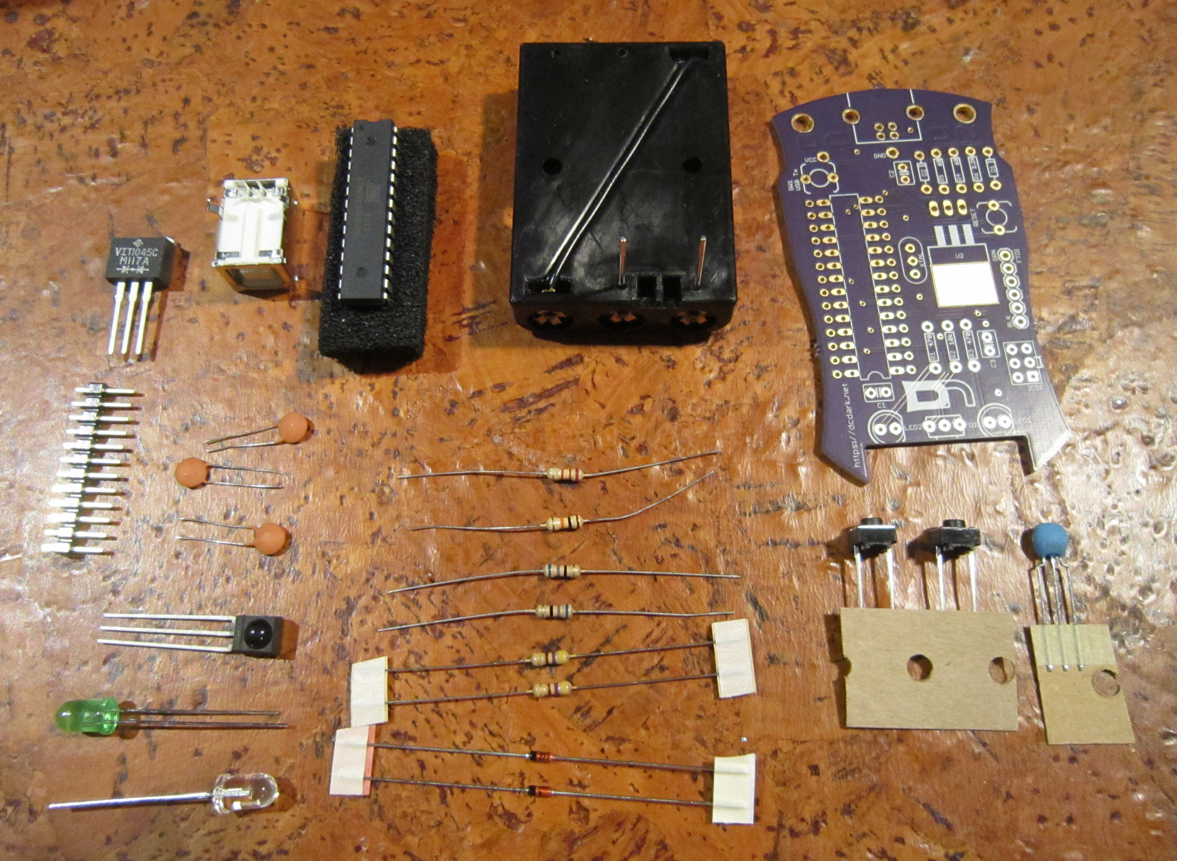
Inspect the parts of your kit. You should have the following items
This is the Darknet ID badge. It is useful in proving your identity to other darknet members, and for you to verify their identity as well.
Inspect the parts of your kit. You should have the following items
This is the Darknet ID badge. It is useful in proving your identity to other darknet members, and for you to verify their identity as well.
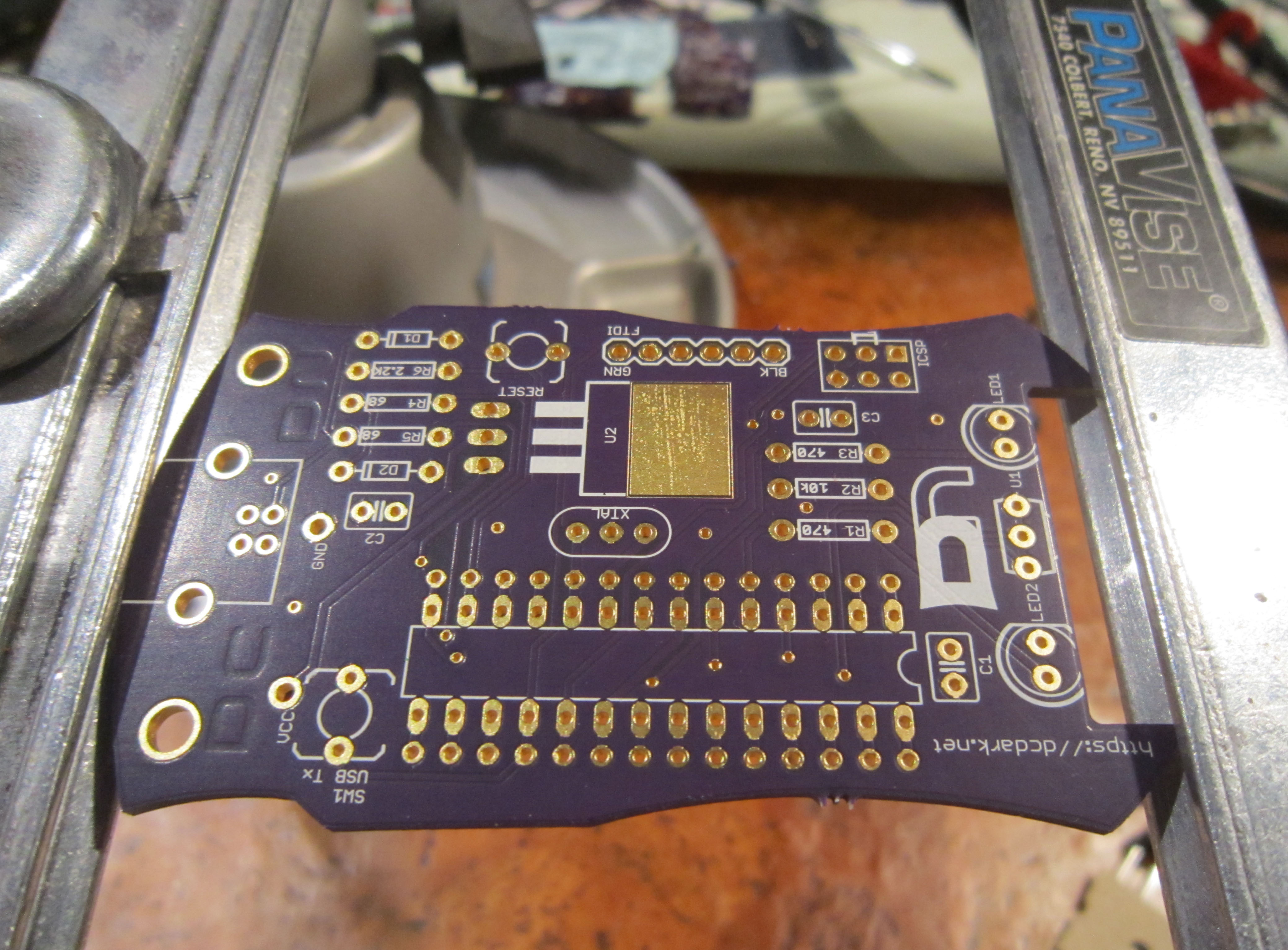
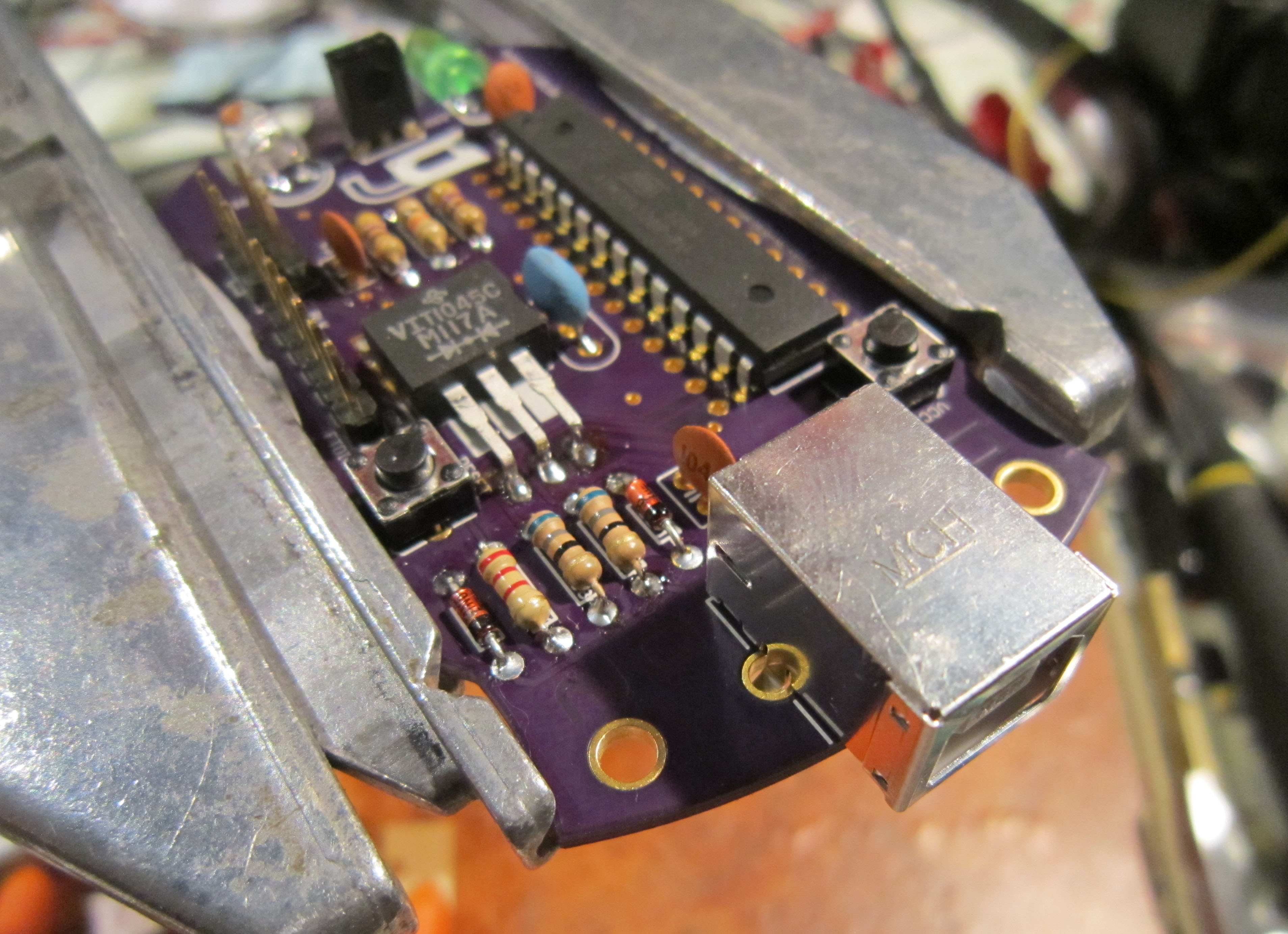
First take a moment to appreciate the PCB. We worked with the people over at OSH Park to get the boards manufactured, and once again they have done a great job.
The kit hardware was designed by agent Krux, and firmware by agent Smitty. Improvements have been made over last year's board. We have a much more powerful micro controller. We have also added an oscillator, and improved the IR transmission by using an infrared receiver module. We've also designed this year's kit to be entirely hackable. All the pins for the micro have been broken out, and use a standard 0.1 inch spacing. This makes it easy to add on boards or other components. It has been designed to be easy to solder, with all through hole components in the kit. The board can be programmed as an Arduino Duemilanove, using the FTDI header pins. Also provided of course is the ICSP header.
The current design files and source are located at https://dcdark.net/2014/hhv-source
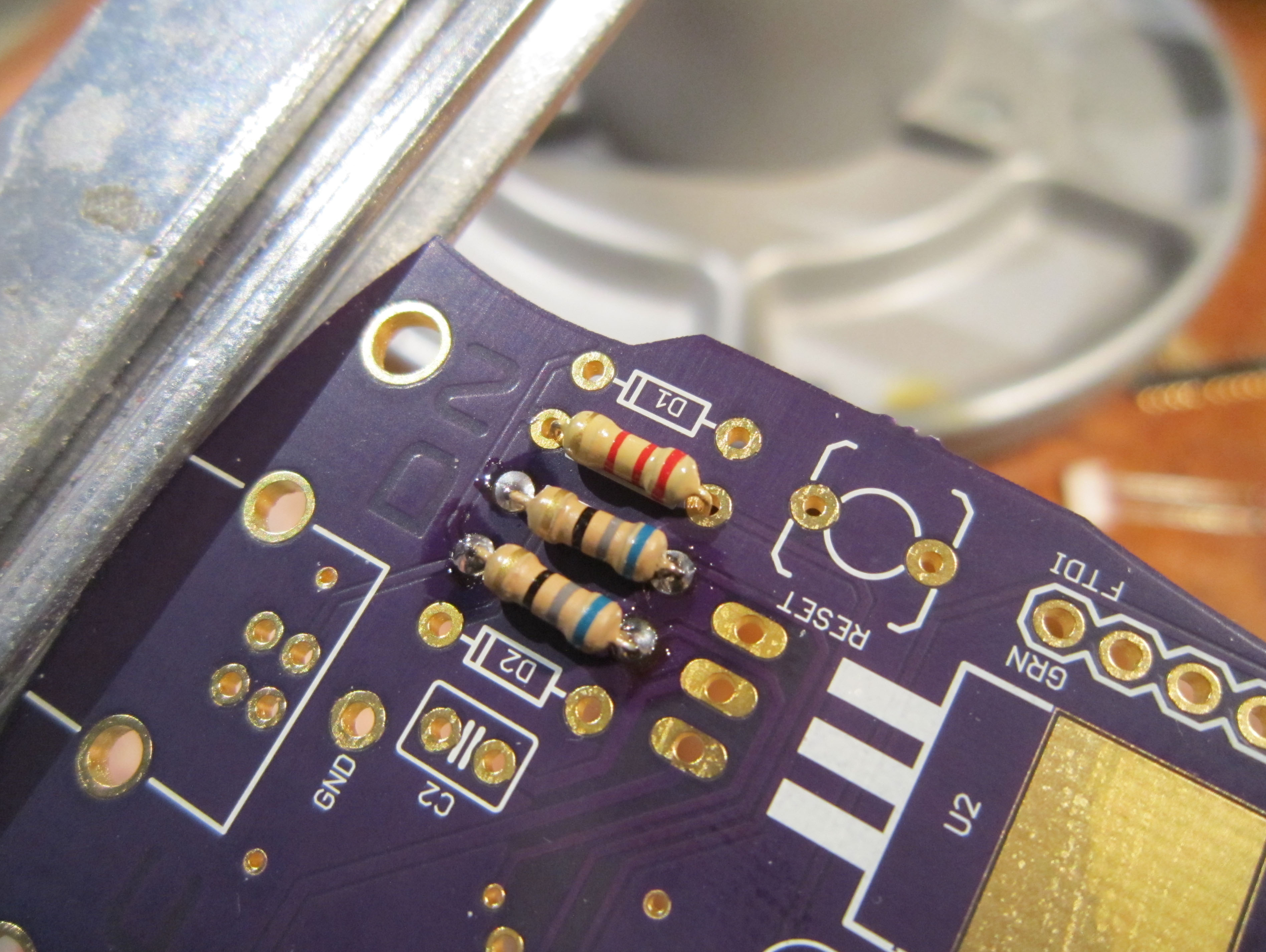
First we will install the current limiting resistors.
Install the R1 and R3, 470 ohm resistors as shown
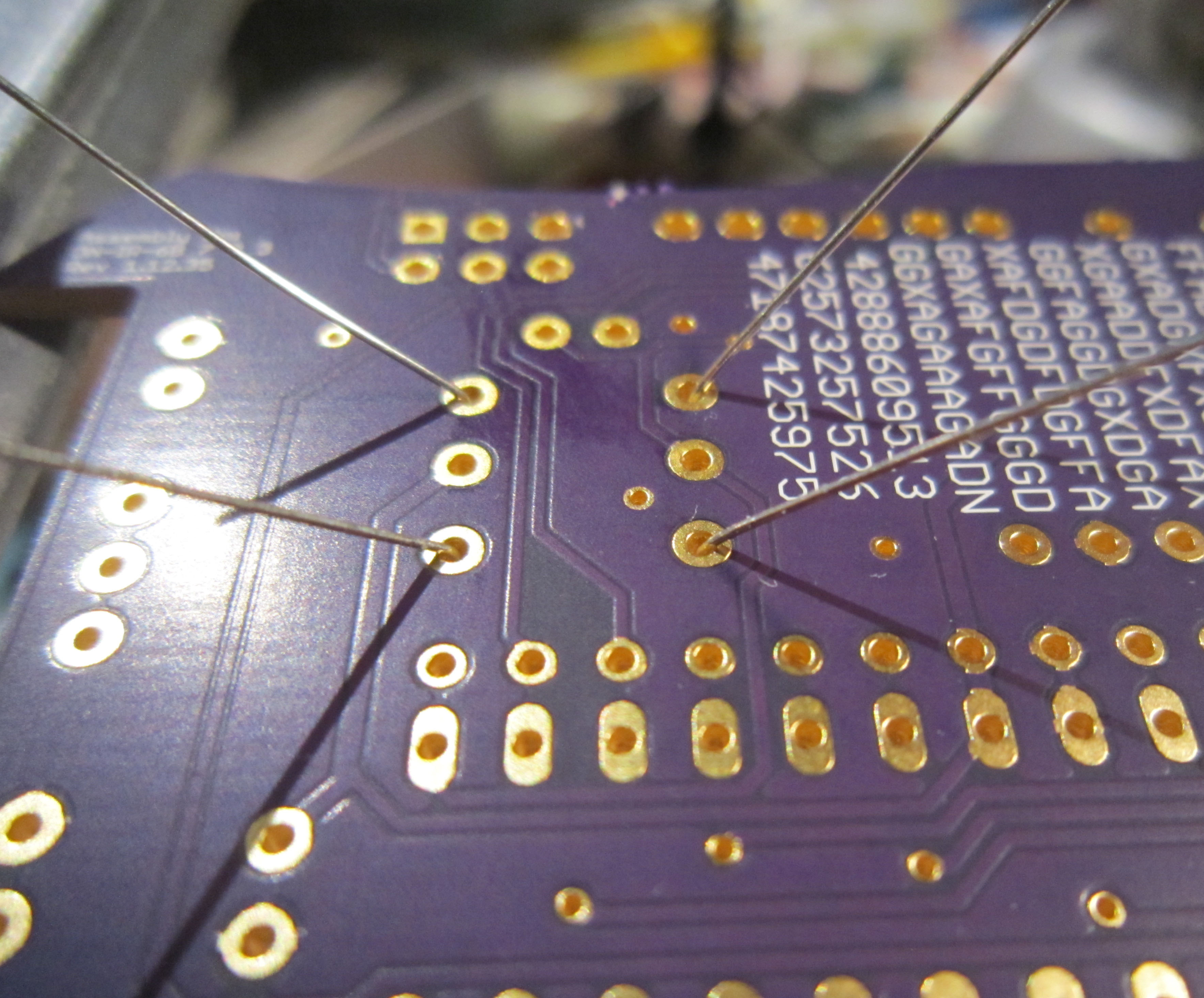
To keep the resistors in place while soldering, you can bend the leads out slightly. This prevents the components from falling out while you are working on the underside of the board.
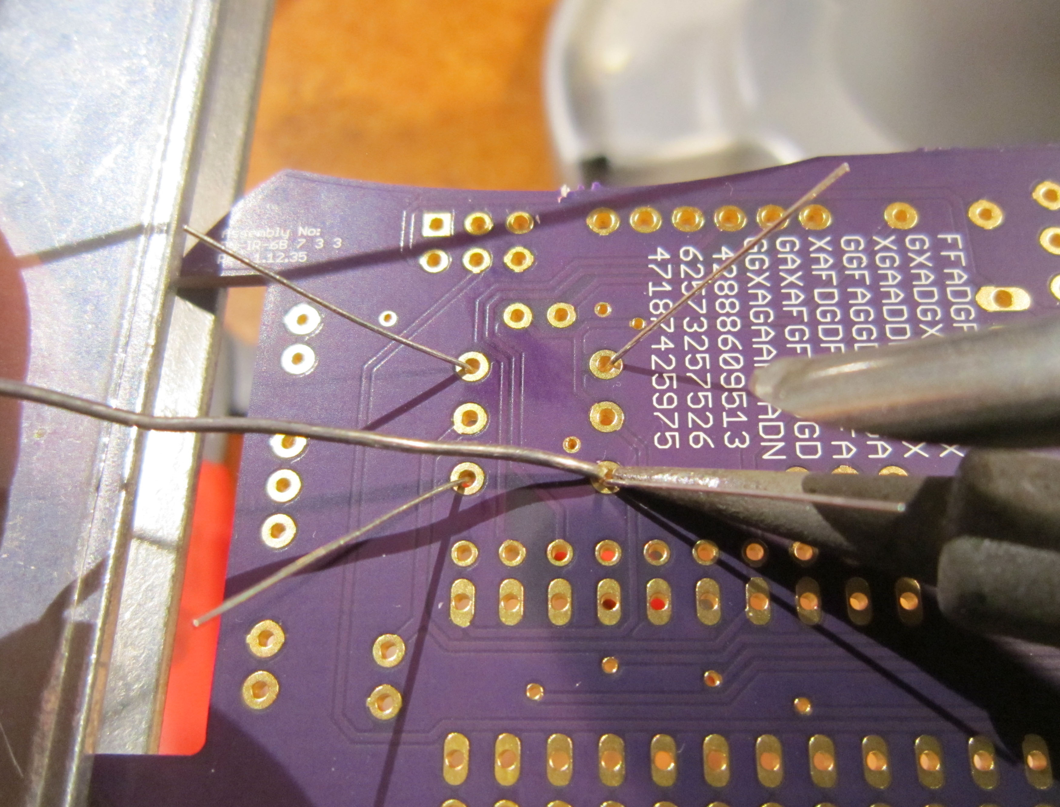
Start by soldering one of the leads.
The key to soldering is to heat up both the pad, the exposed copper on the PCB, and the component, the lead going through the PCB, at the same time. Then feeding in solder on the opposite side of the component. Try to not use the very tip of the iron, but the side of the iron near the tip. This gives better heat transfer, and makes soldering easier. Both parts need to be hot enough to melt the solder, otherwise you will get what is known as a cold solder joint. It means the solder only attached itself to one of the two surfaces, and will cause problems with your circuit. A proper solder joint should look like a small cone. Generally if you still see parts of the copper pad, you need more solder. If the solder joint is larger than the pad and bulging outward then there is too much solder.
Sparkfun Electronics has an excellent tutorial on soldering located here:https://learn.sparkfun.com/tutorials/how-to-solder---through-hole-soldering
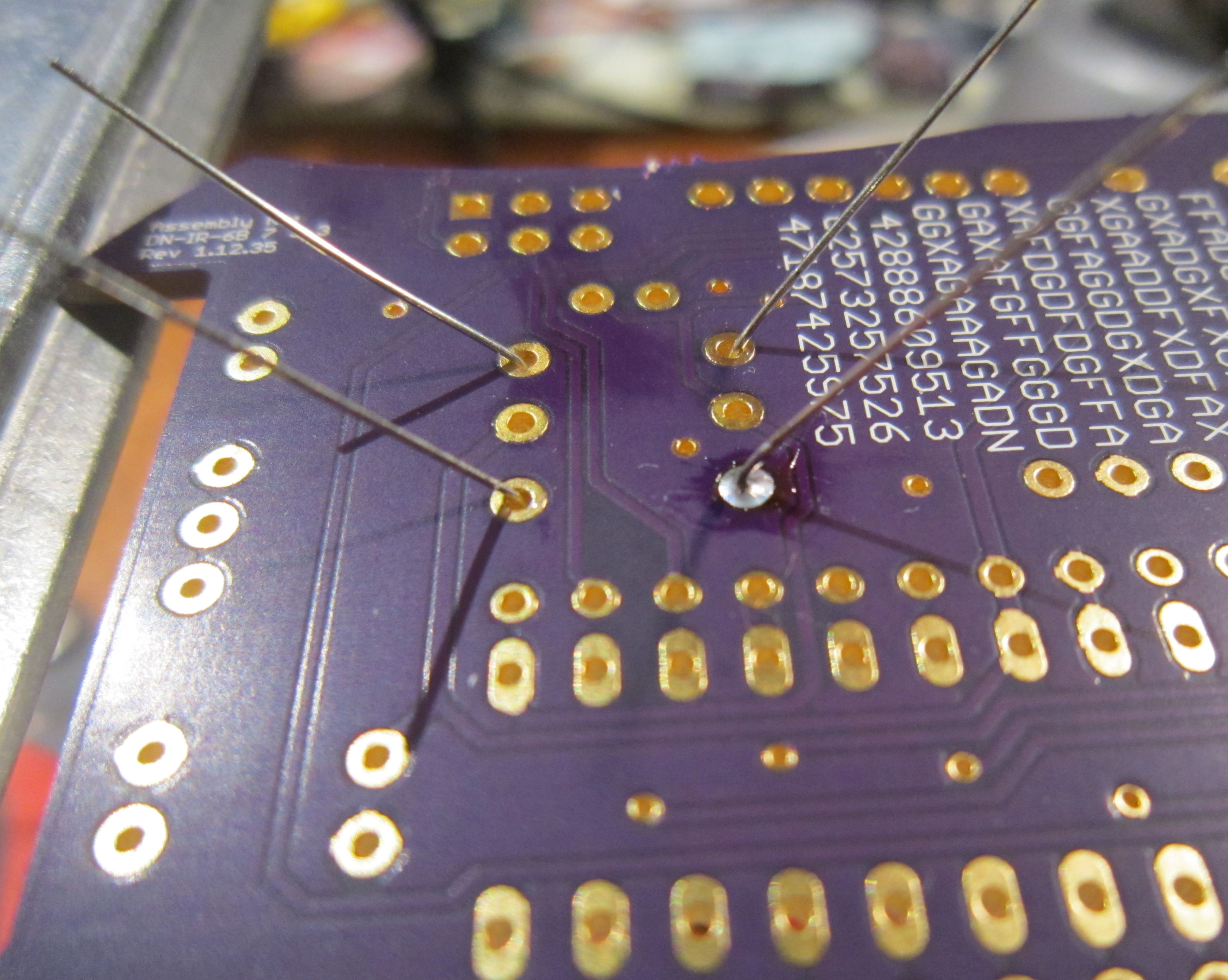
As you can see here you have a nice small cone shaped solder joint.
This is also a good time to check that the components on the top side of the board are still flush with the surface. It is much easier to reheat one solder joint and reposition the part, than it is once you have soldered more than one lead.
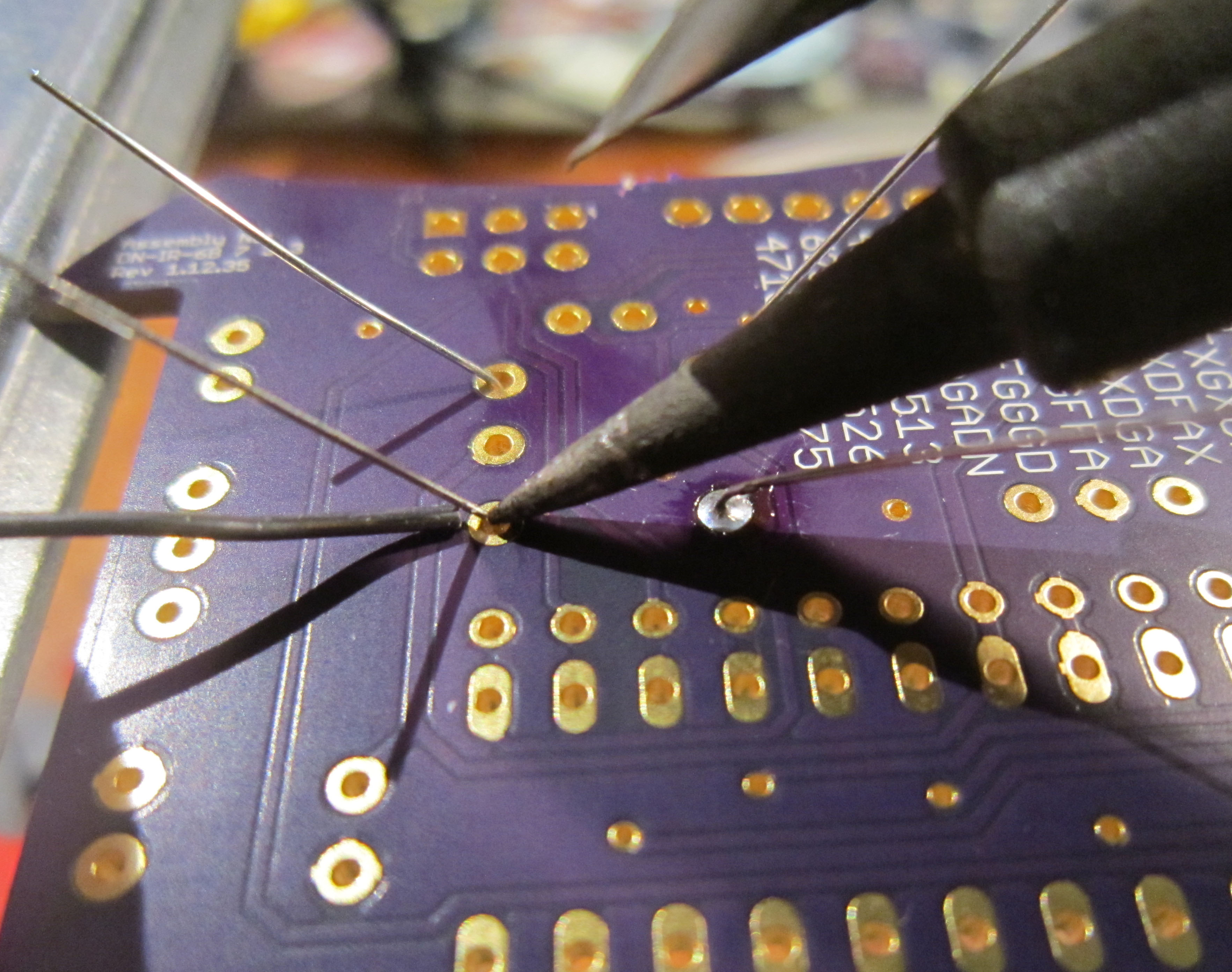
Next solder the other lead of the resistors.
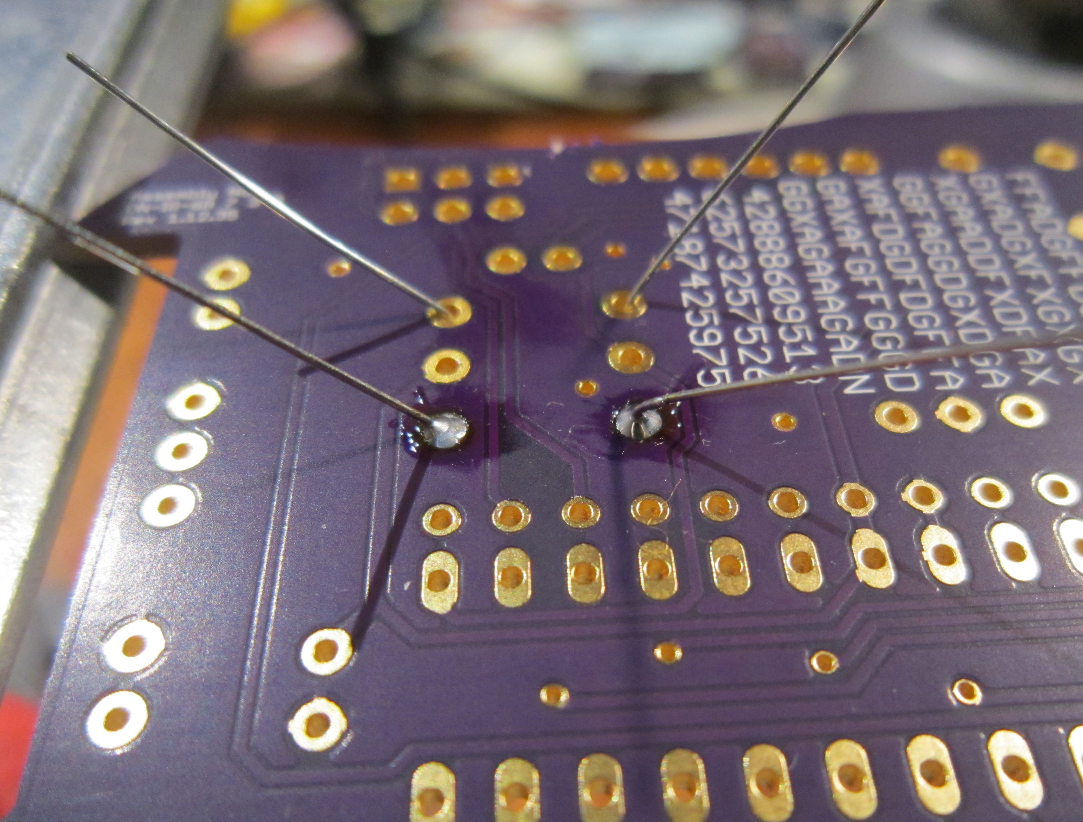
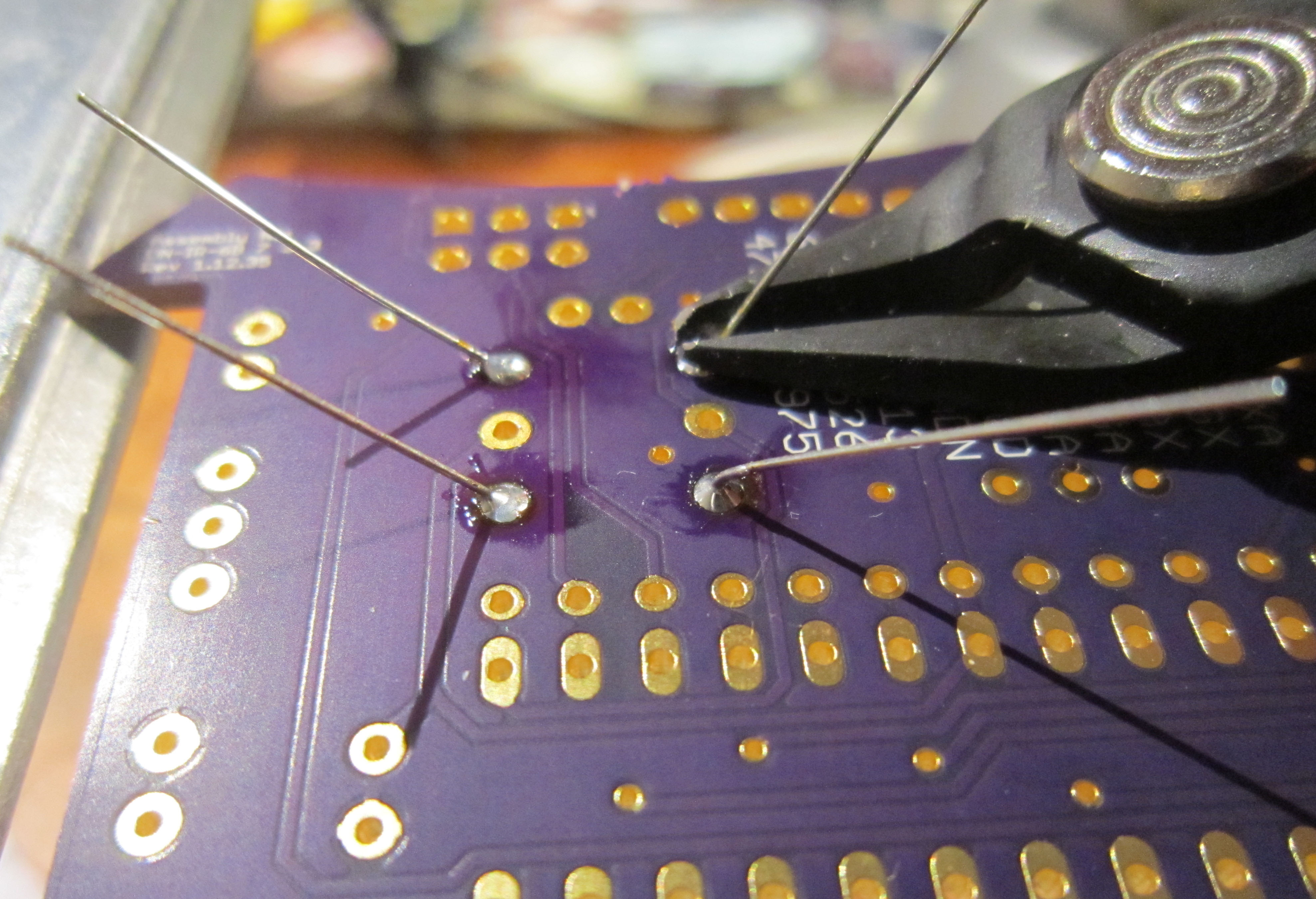
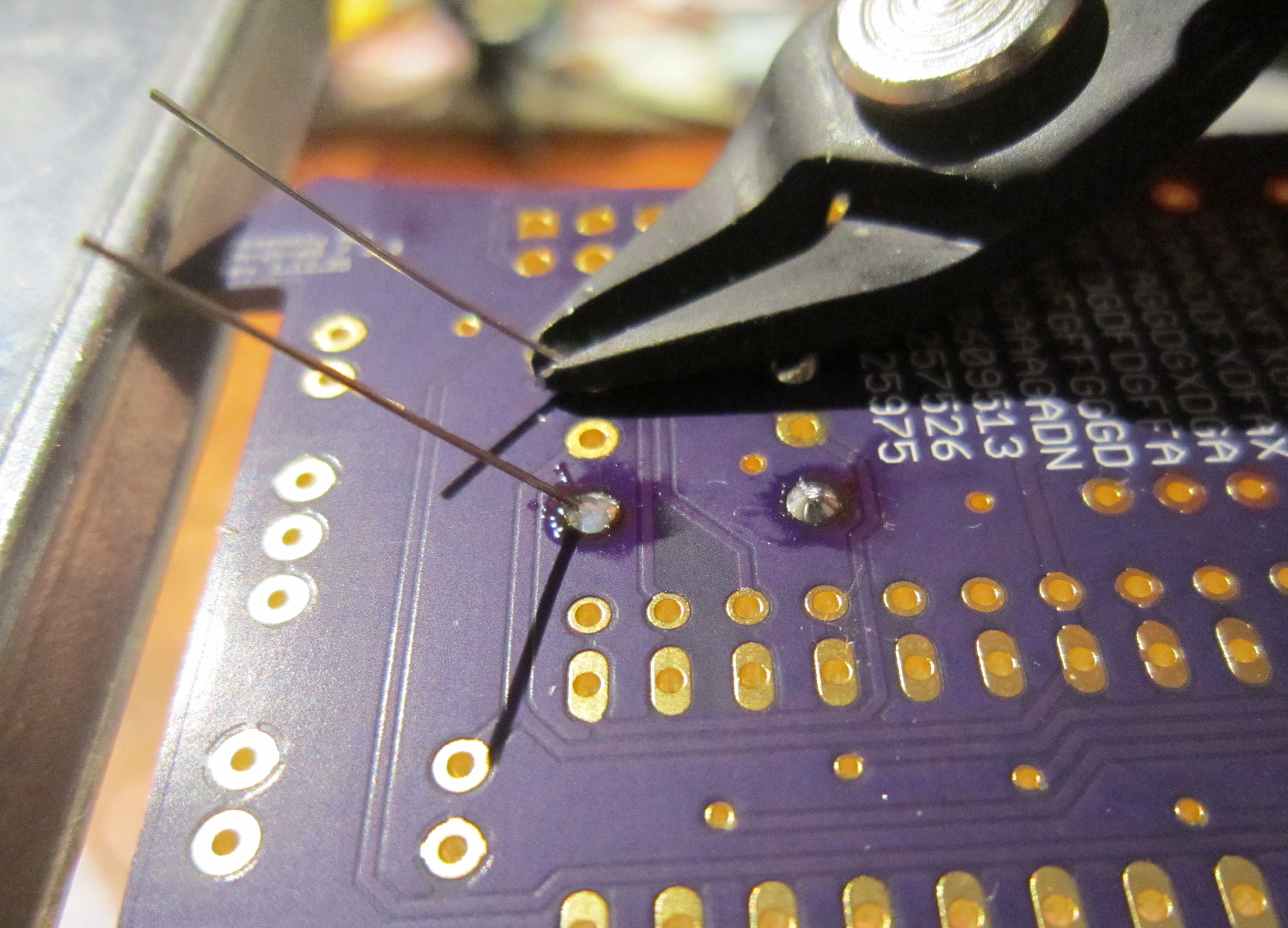
Finally cut the leads flush with the PCB using a pair of diagonal or flush cutters.
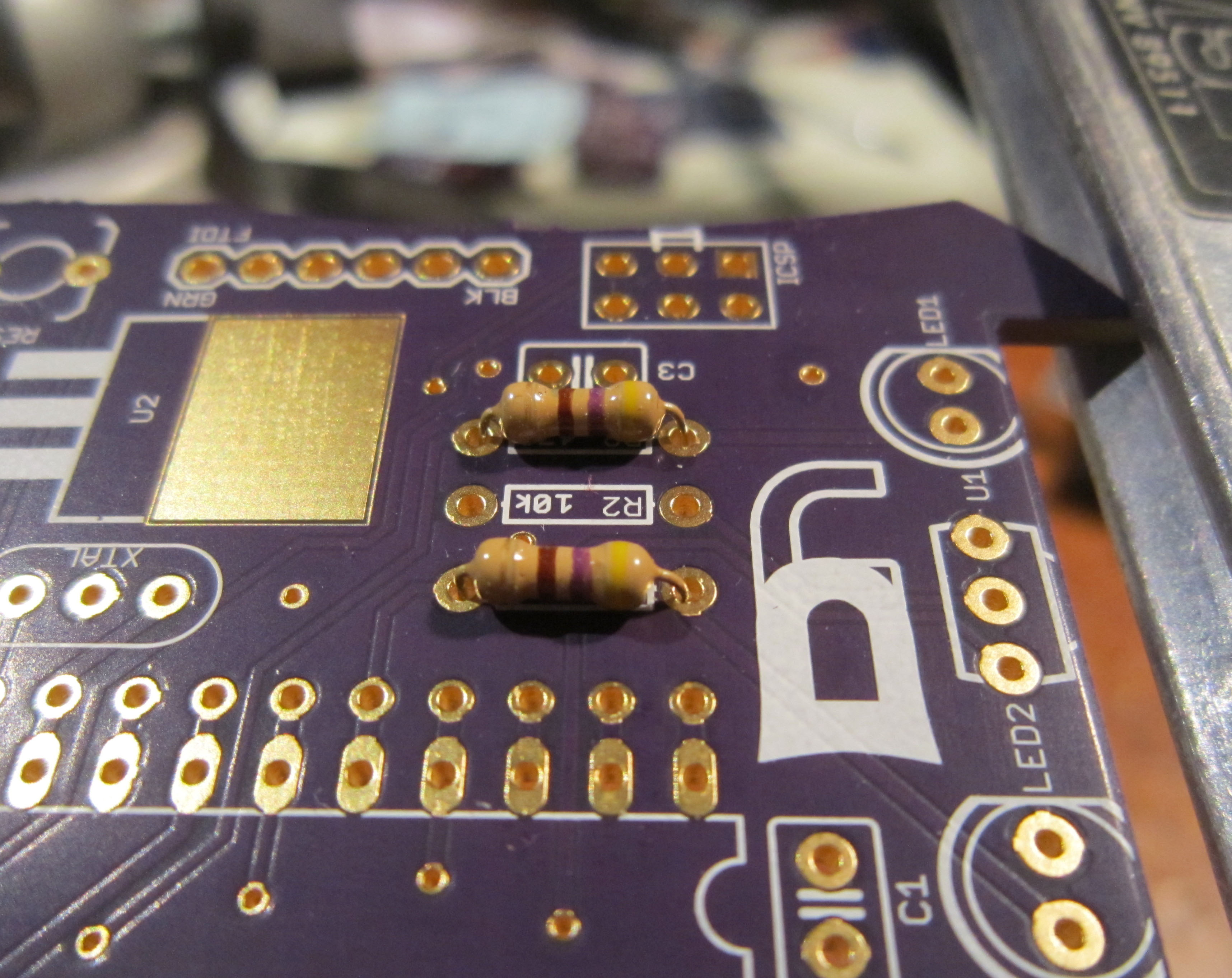
Repeat the above steps and install the 10k ohm resistor R2.
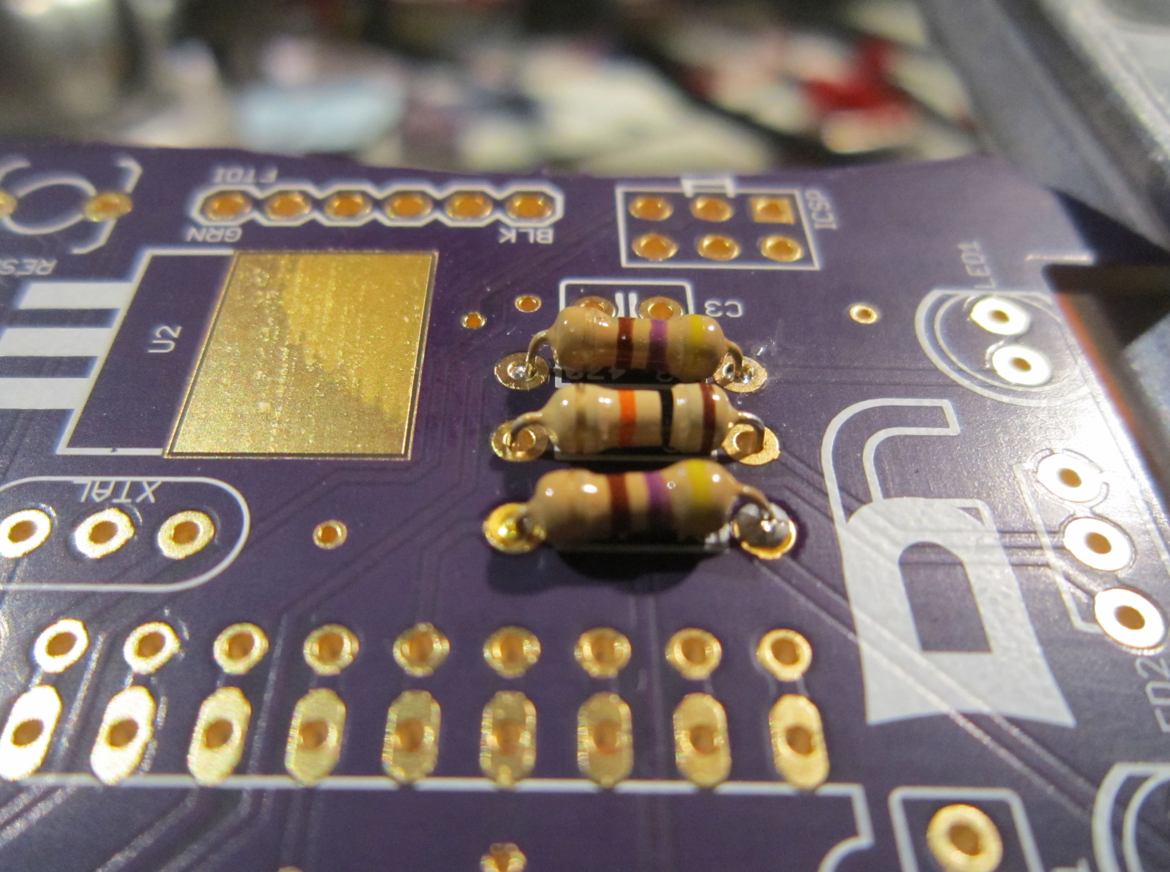
Repeat the above steps and install the 68 ohm resistors R4 and R5.
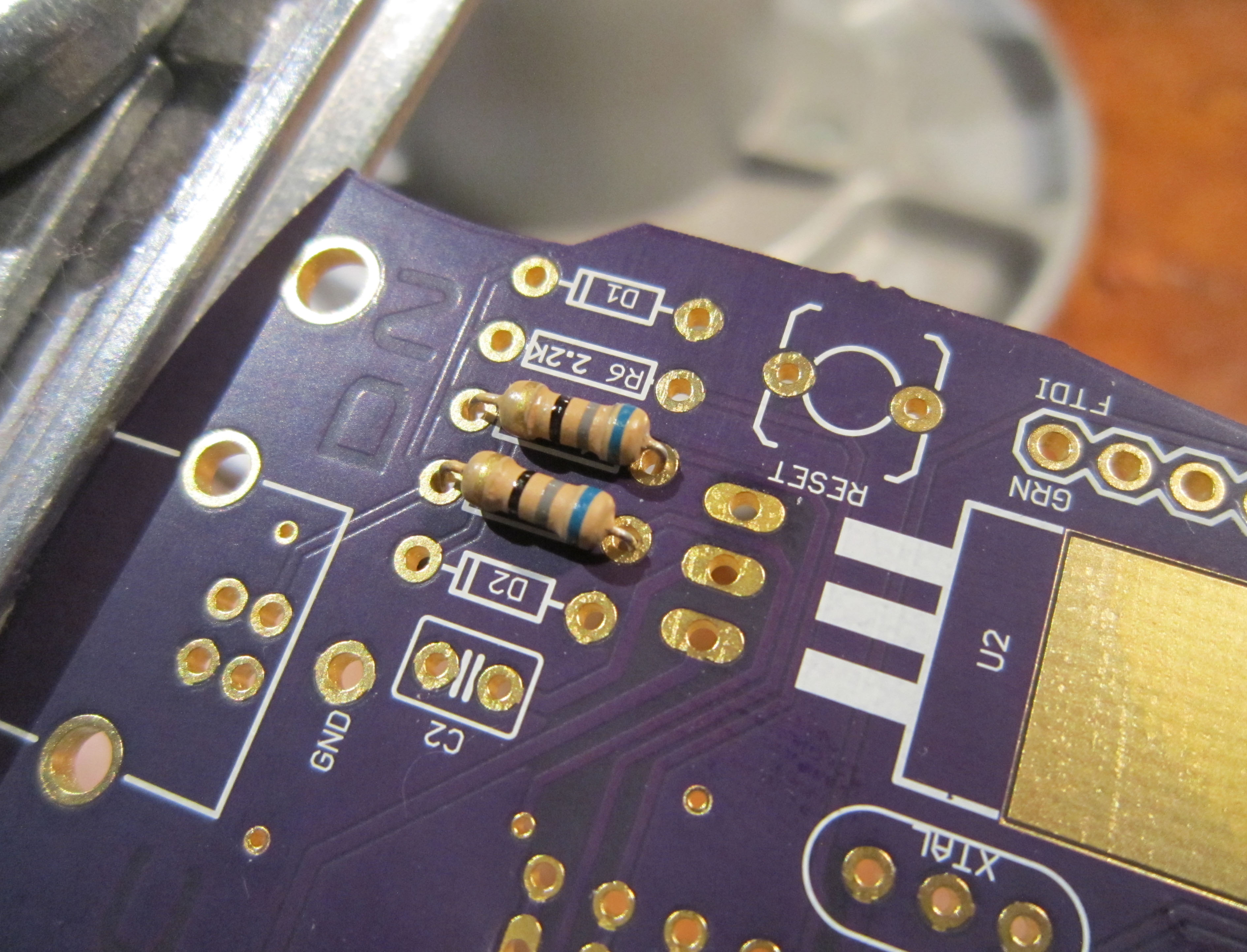
Repeat the above steps and install the 1.5k ohm resistors R6.
Note the silk screen and picture show a 2.2k resistor. For greater reliability, this part was changed to a 1.5k ohm resistor in the kit.
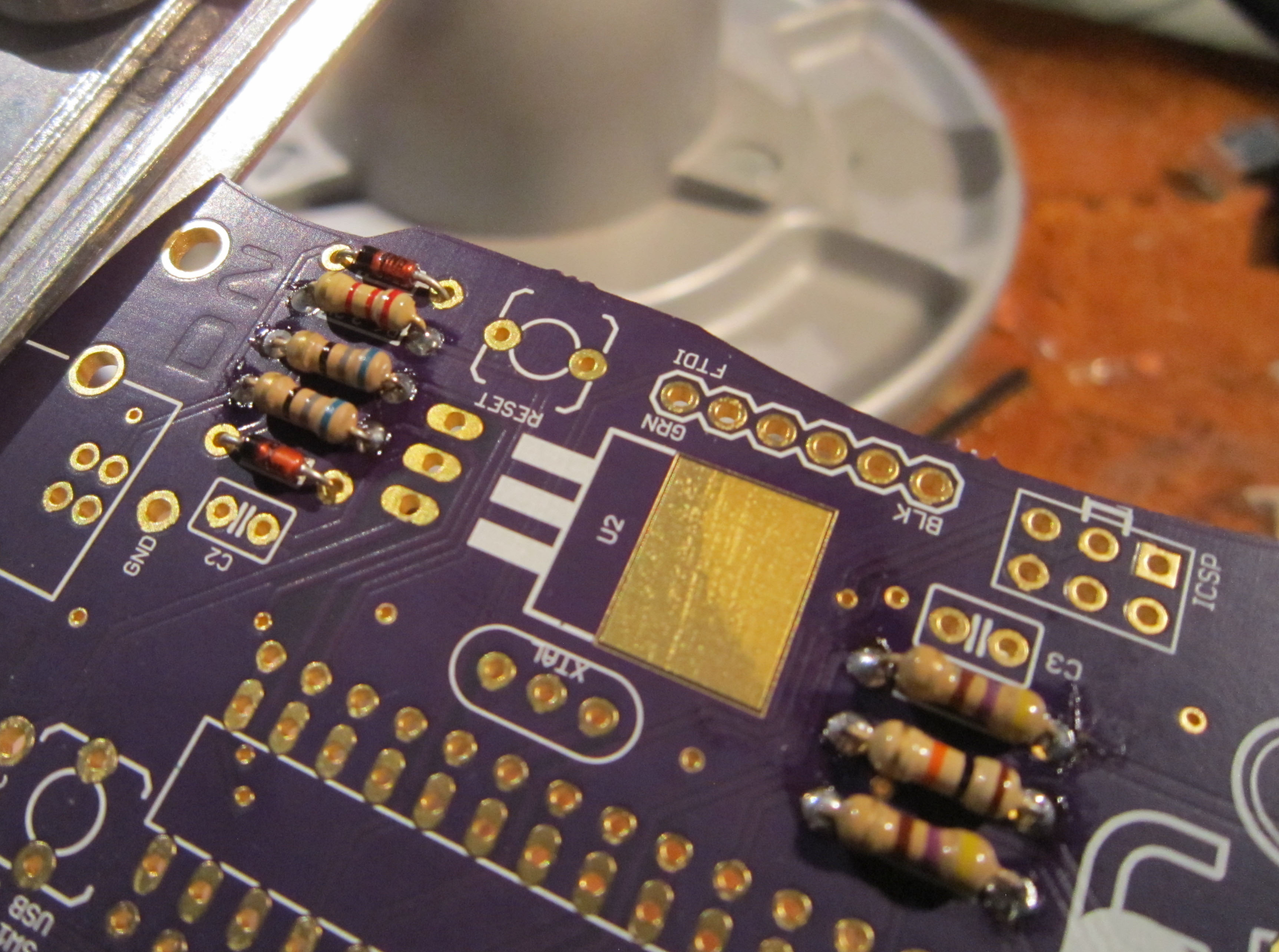
Install the two 3.6 volt zener diodes D1 and D2.
Note these components are polarized. Be sure and match the stripe on the component with the stripe indicated on the board.
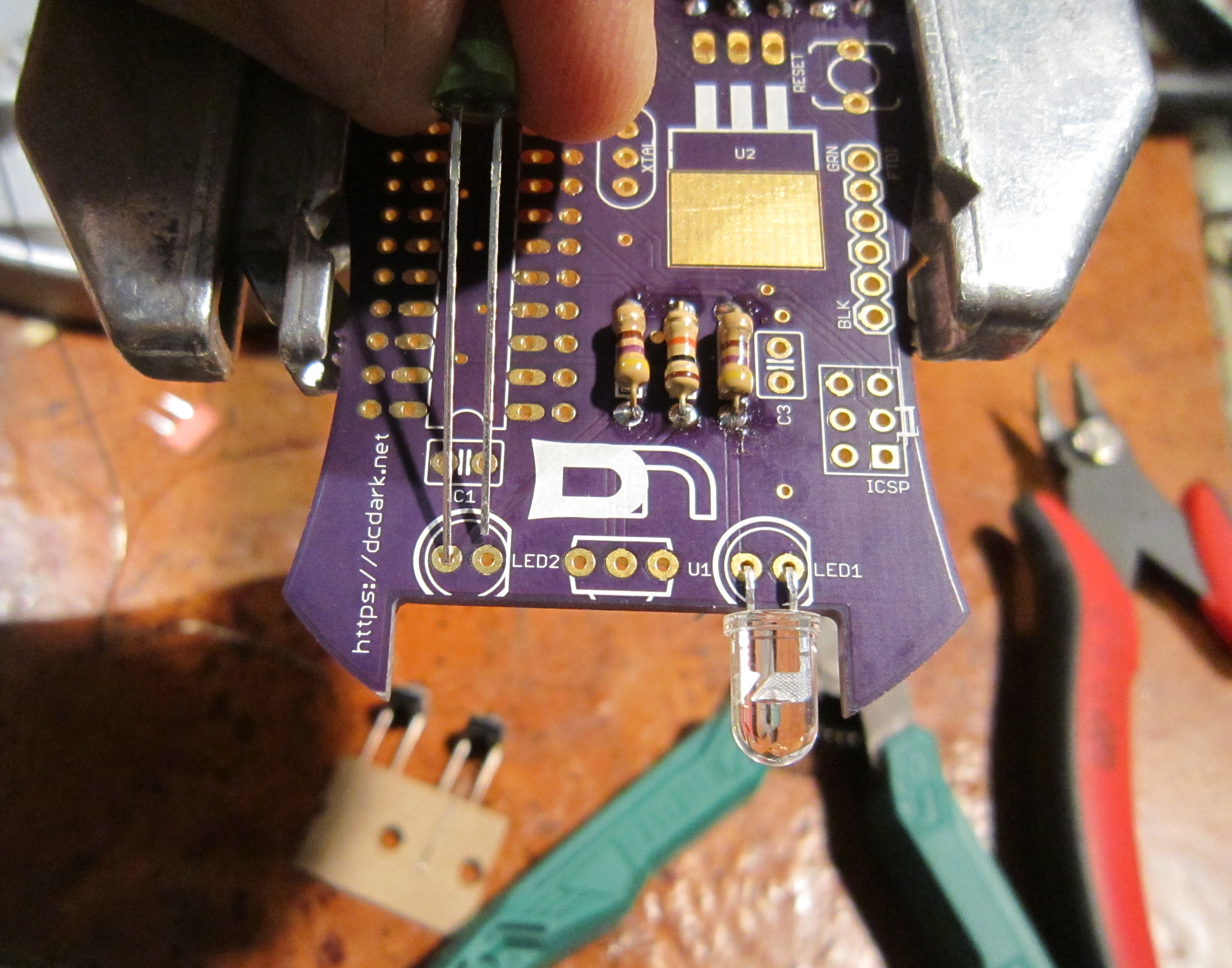
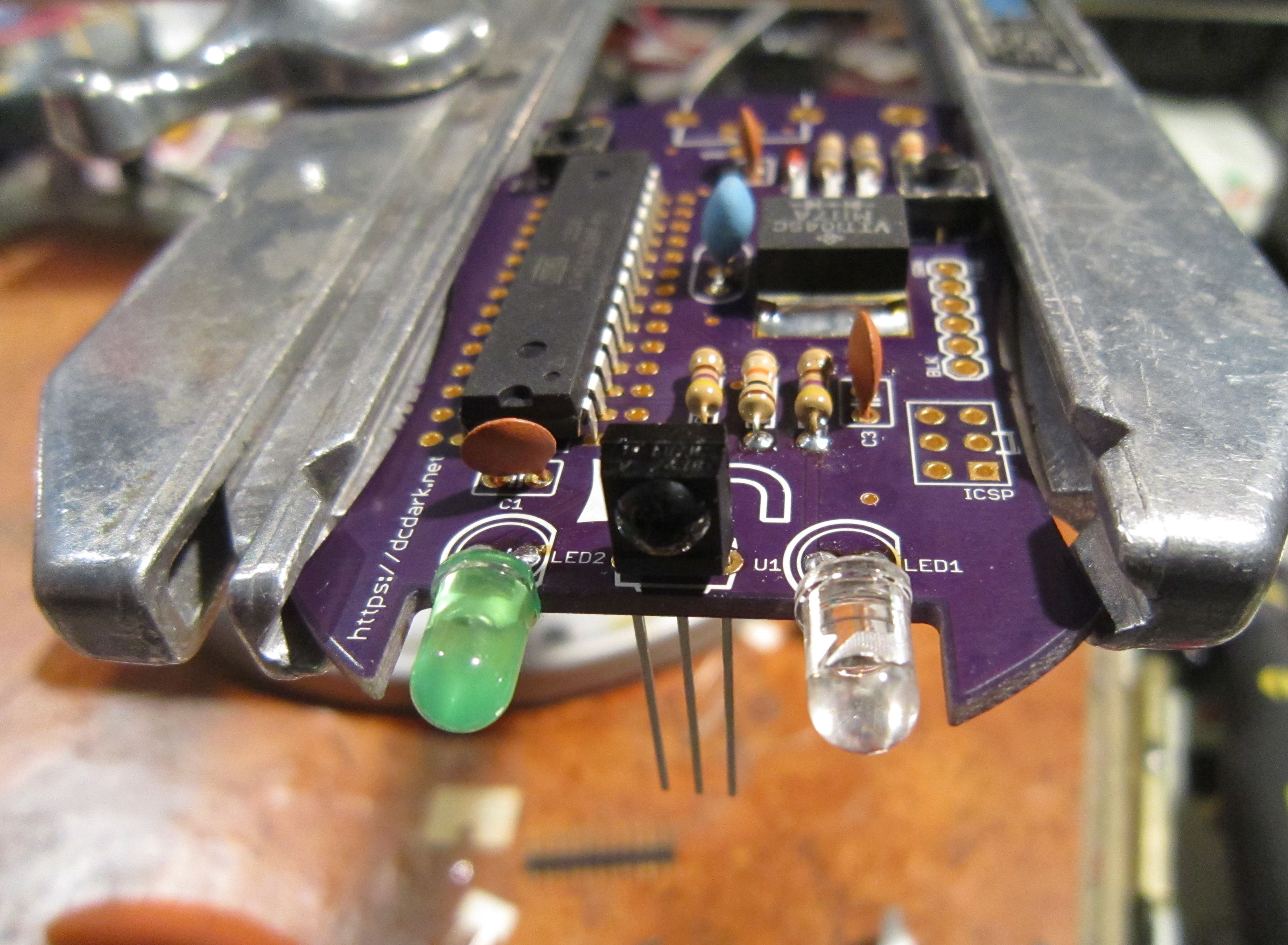
Install the infrared LED (the clear LED) at LED1. The infrared LED will be on the side of the PCB where the ICSP programming header is located.
Install the green LED at LED2. The green LED will be on the side of the PCB where the microcontroller is located.
Note the LED is polarized. The flat of the LED indicates the ground, and the longer lead indicates positive.
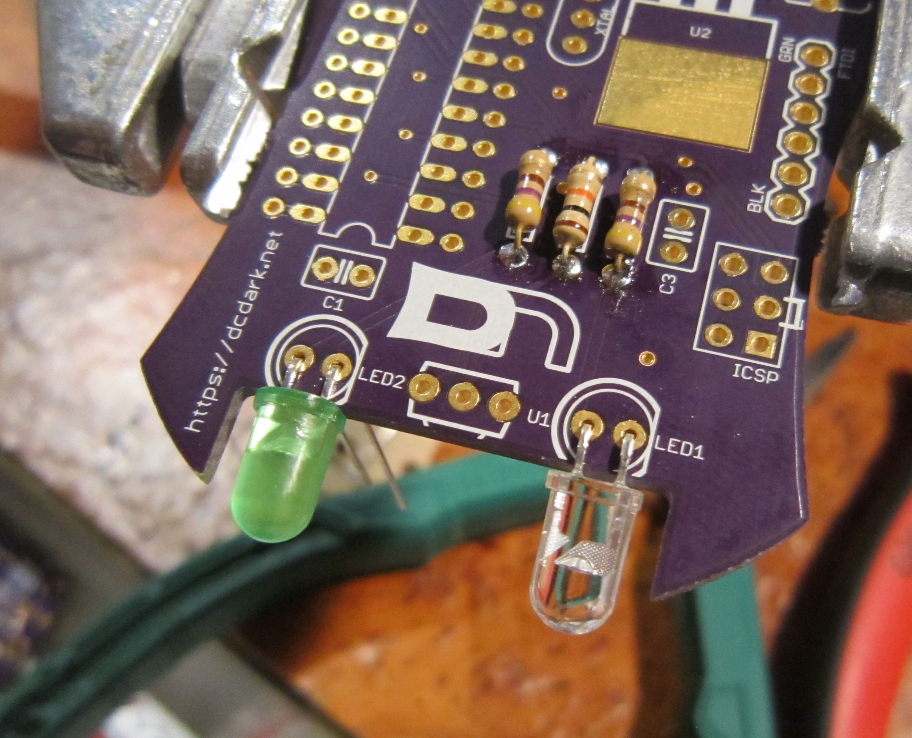
The LEDs should be installed so they are pointing toward the bottom of the badge as shown to allow for infrared communication.
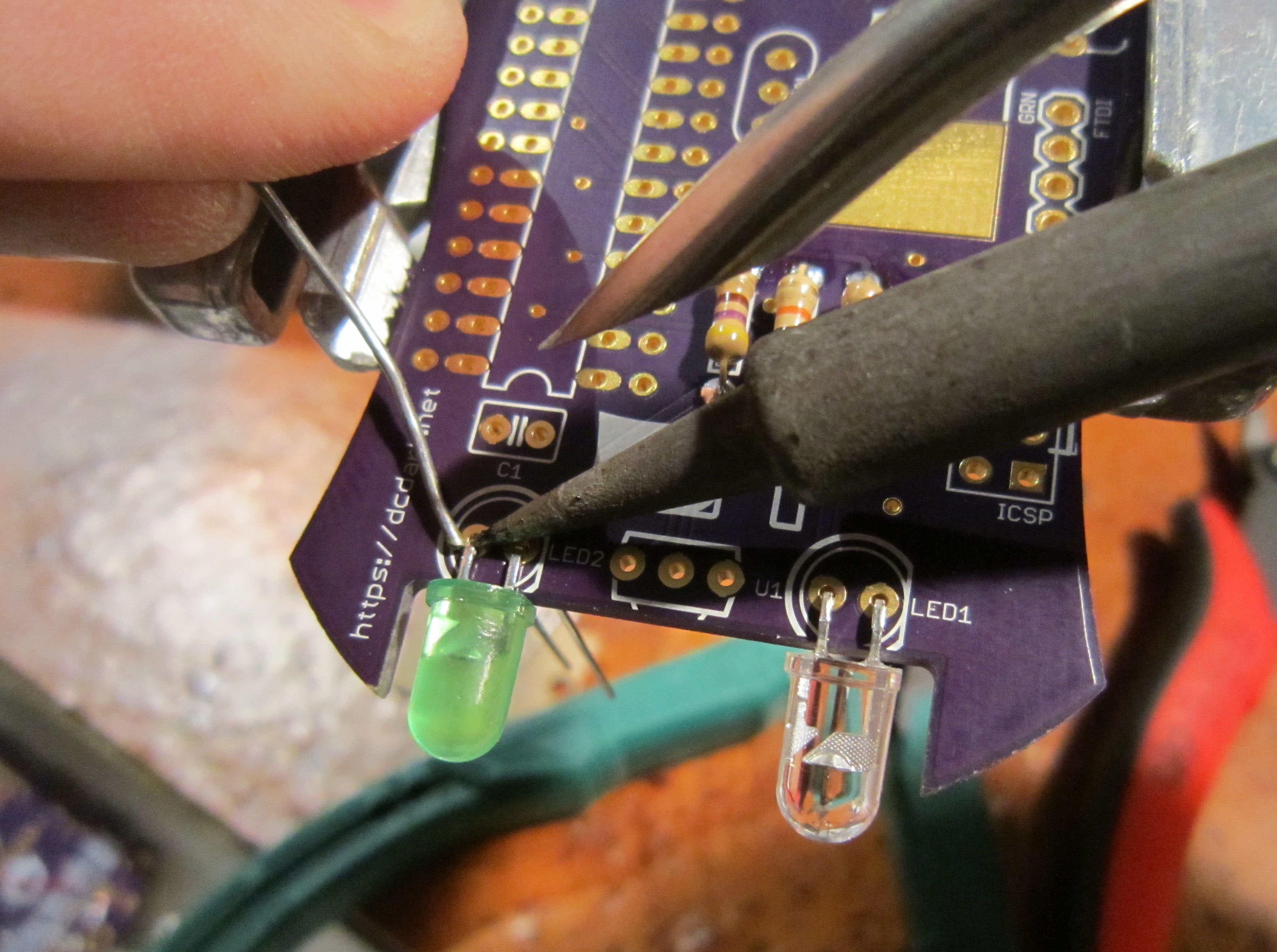
Solder the LEDs on the top side of the board. This will help hold the LEDs in place structurally.
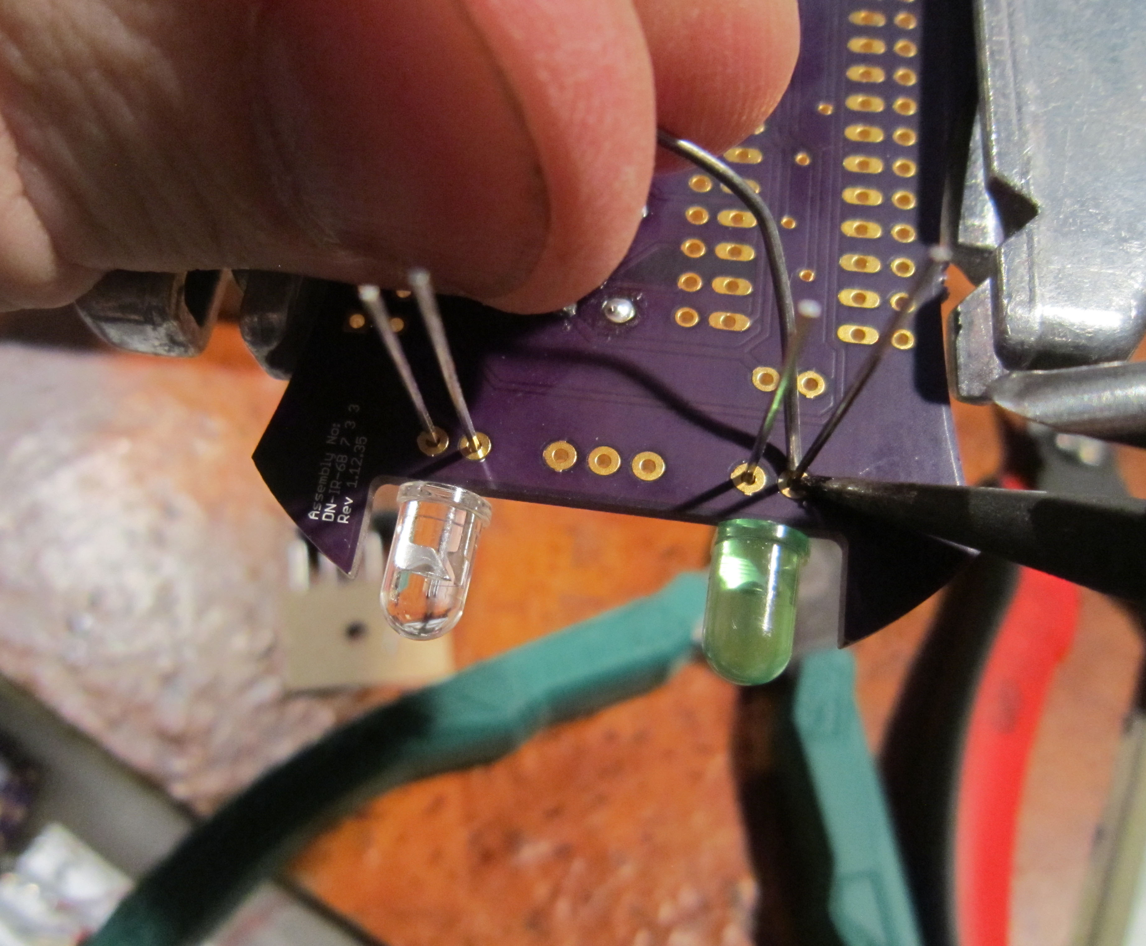
Solder the LEDs on the under side of the board.
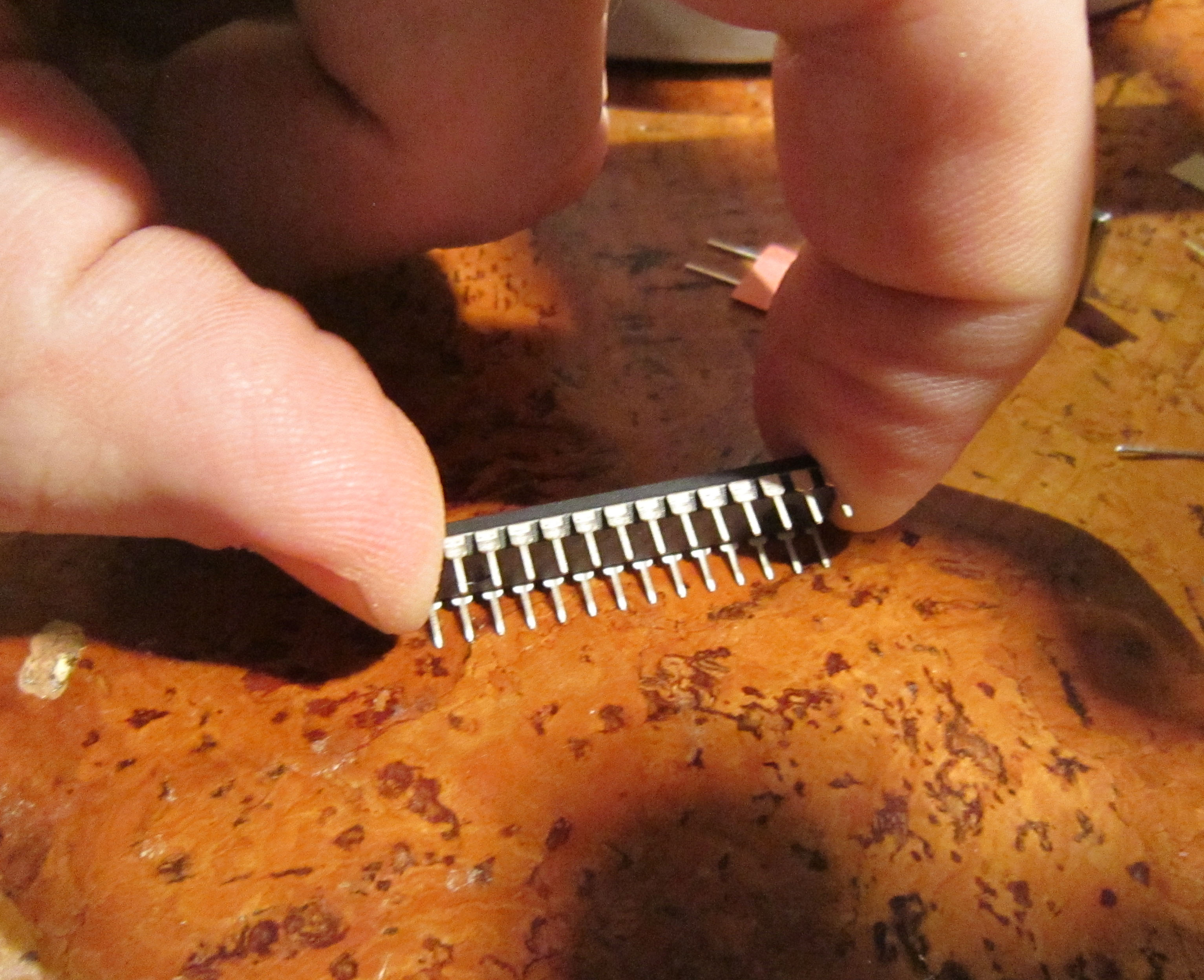
The pins on the microcontroller come splayed out slightly, and need to be straightened to install in the board. An easy way to do this is to rock the chip gently on a flat surface to bring the pins parallel with one another.
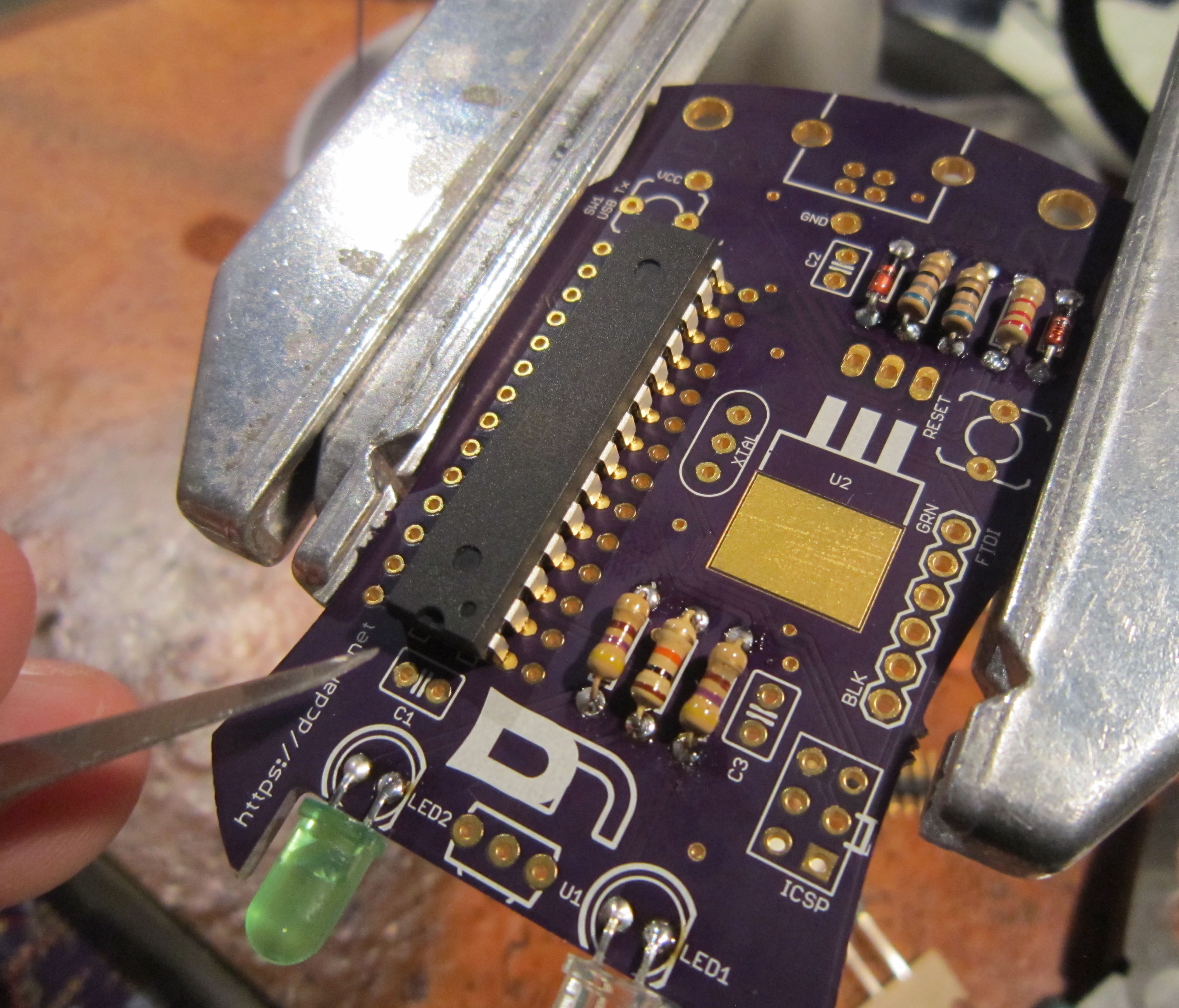
Install the chip. The micro has a notch on one end, which indicates polarity. This will match up with the notch mark on the silk screen.
Solder all the pins on the underside of the board.
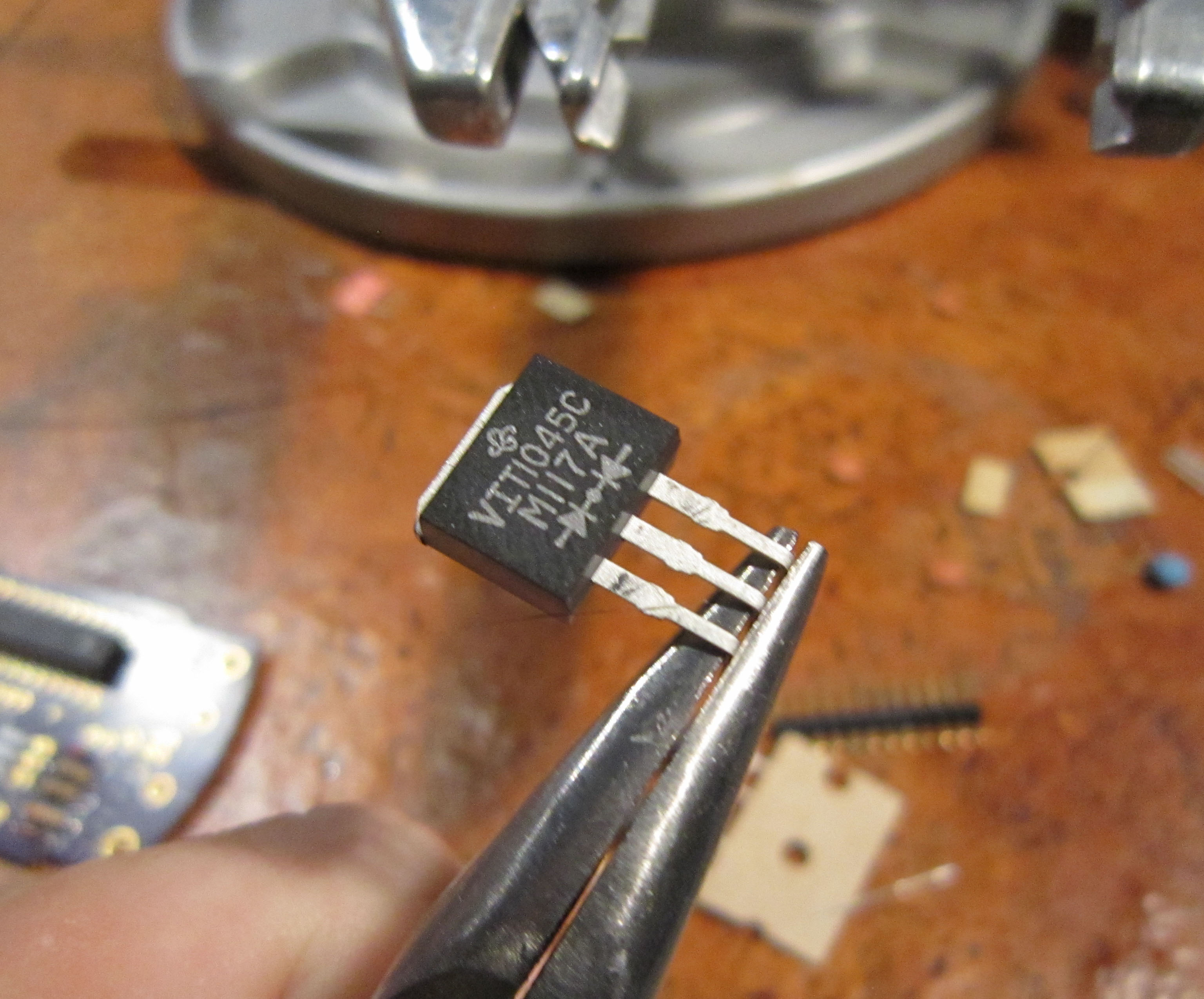
The diode bridge provided power isolation between the batteries and USB/FTDI/ICSP power
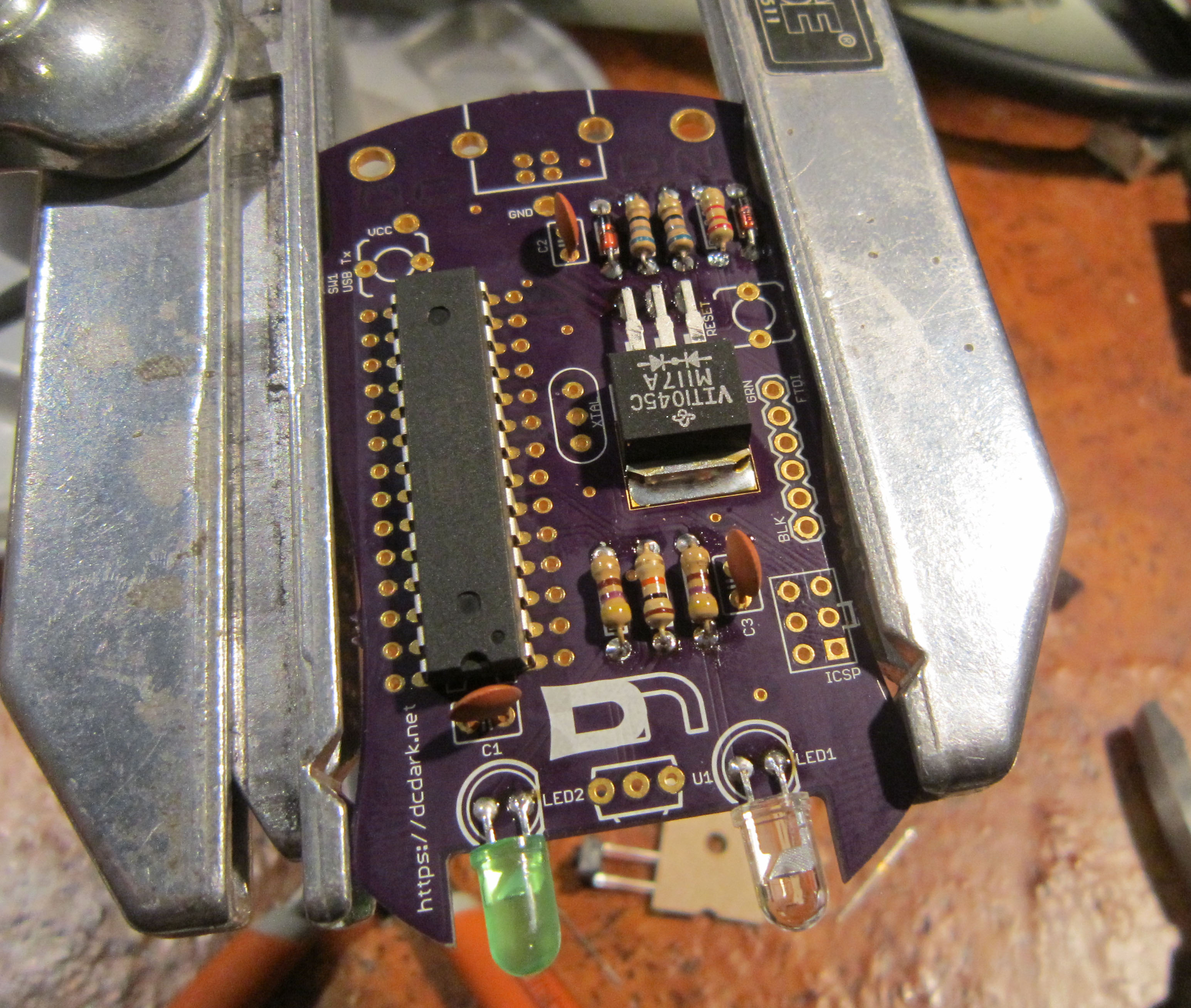
Bend the pins at a right angle as shown. The bend should be about 7mm from the component package, as shown.
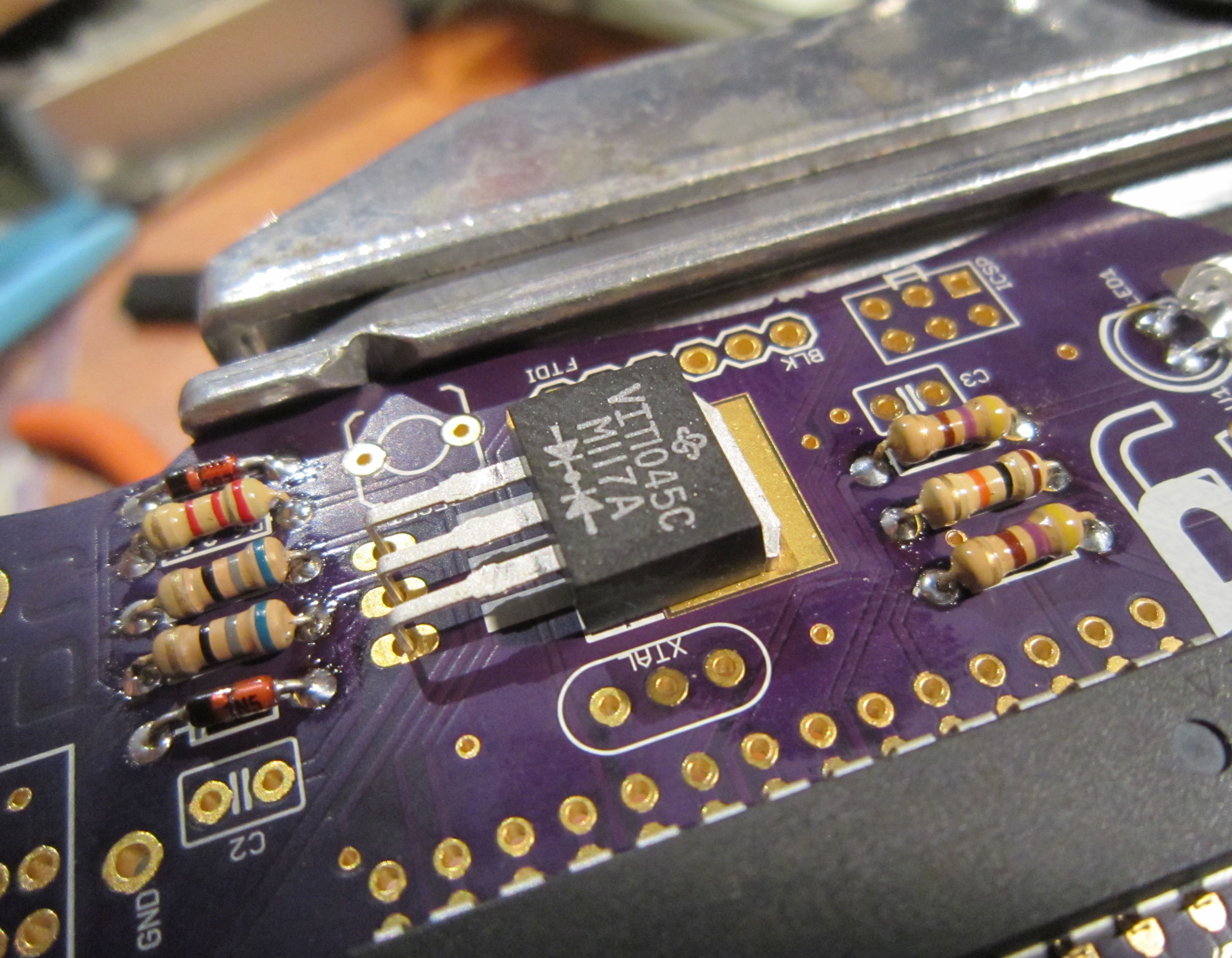
Install the diode bridge
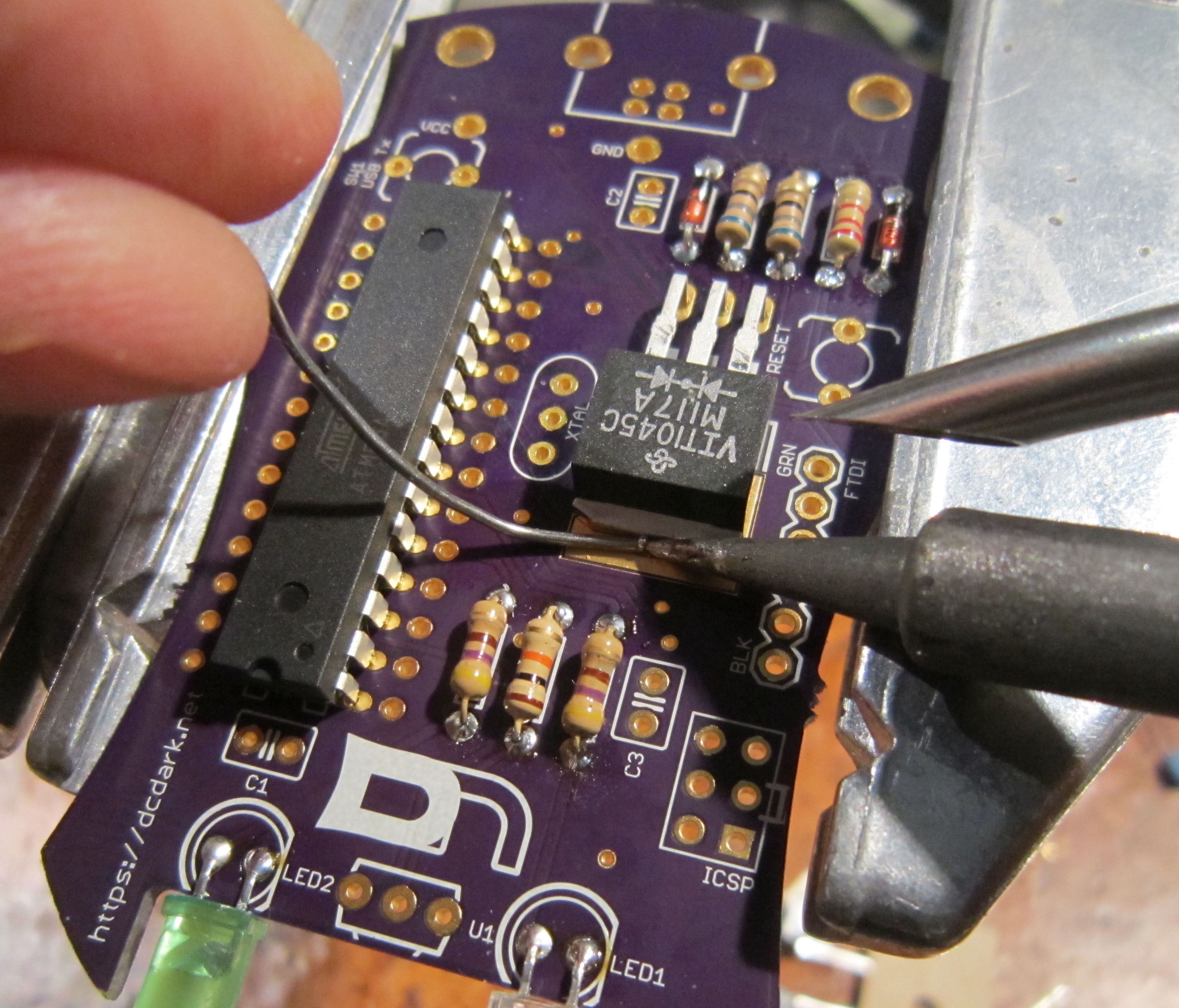
Solder the pins on the underside of the board, then solder the tab on the top side of the board
The tab will require quite a bit of heat. Use the flat of the soldering iron to heat the pad and component tab at the same time.
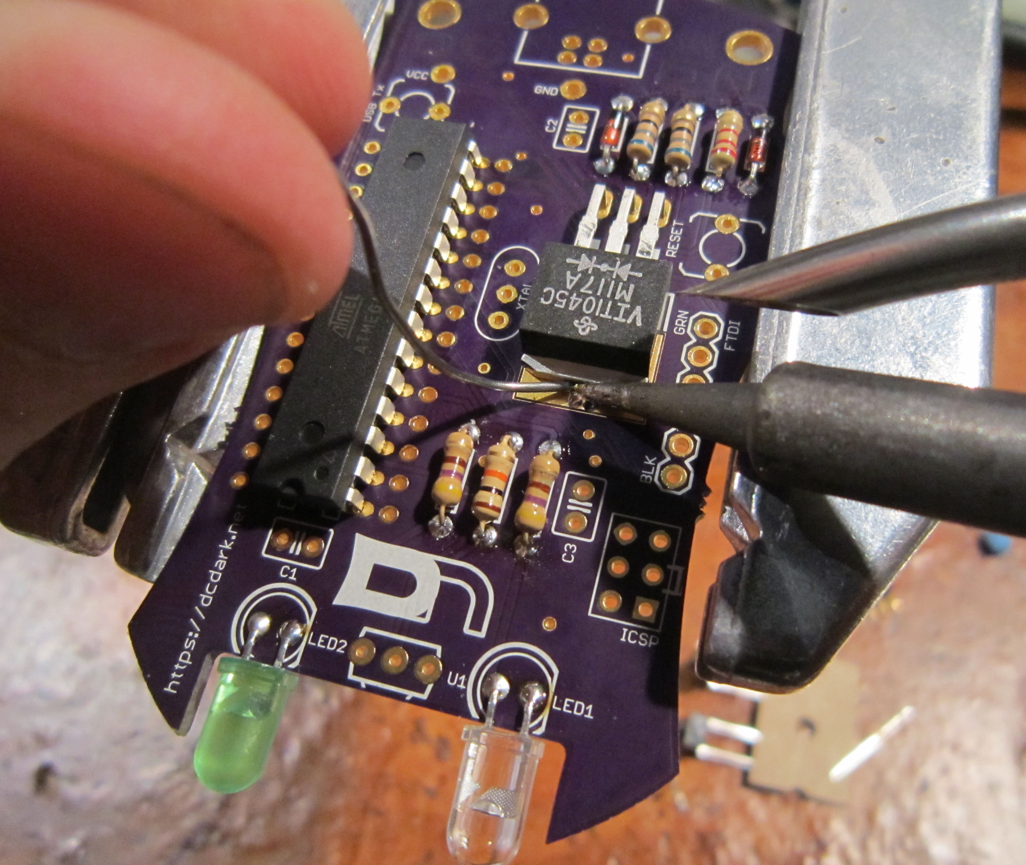
After several seconds, the components will be hot enough and you can start adding solder.
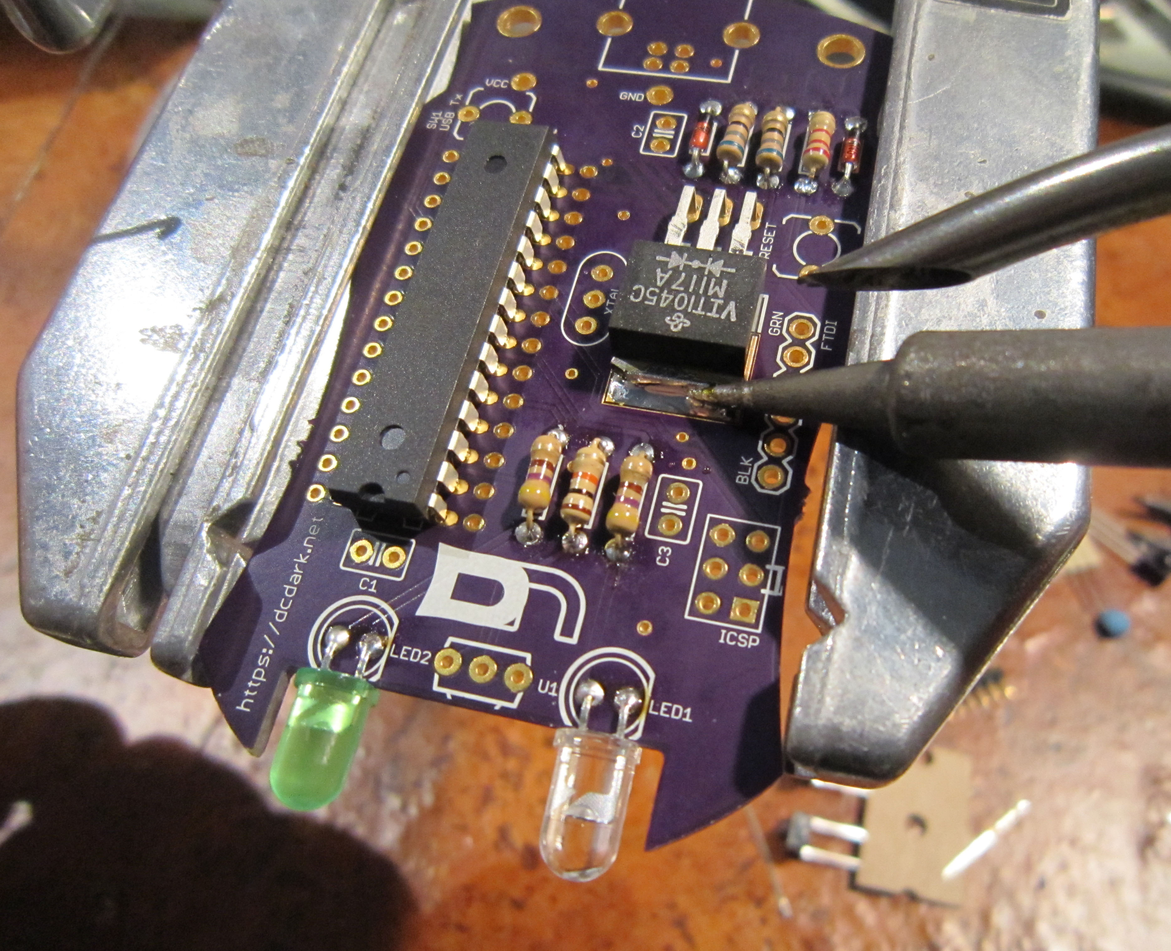
Start adding solder, and slide the soldering iron across the solder joint to to flow the solder over the component and pad.
Install the bypass capacitors in C1, C2, and C3
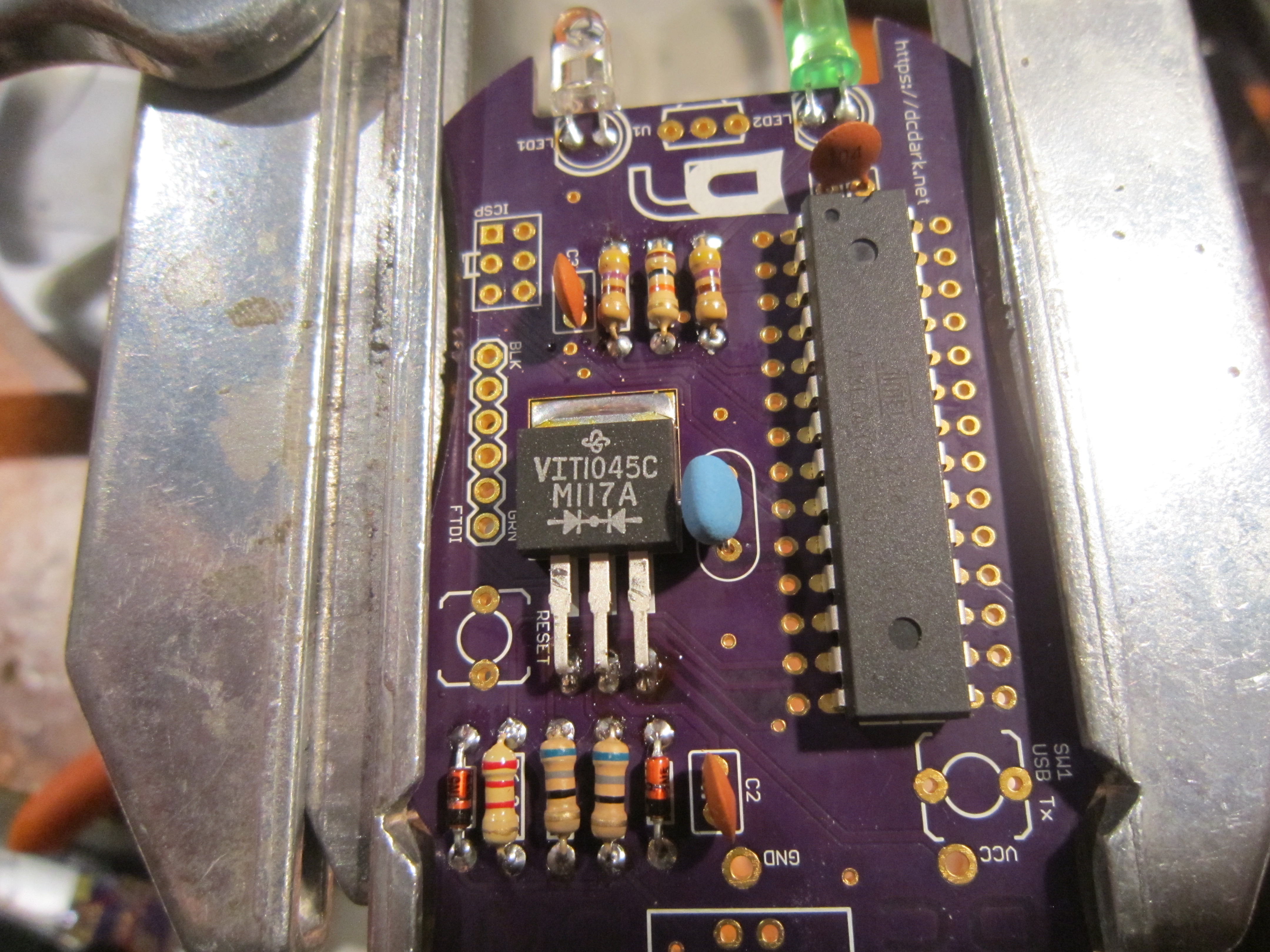
Install the 16Mhz resonator at XTAL
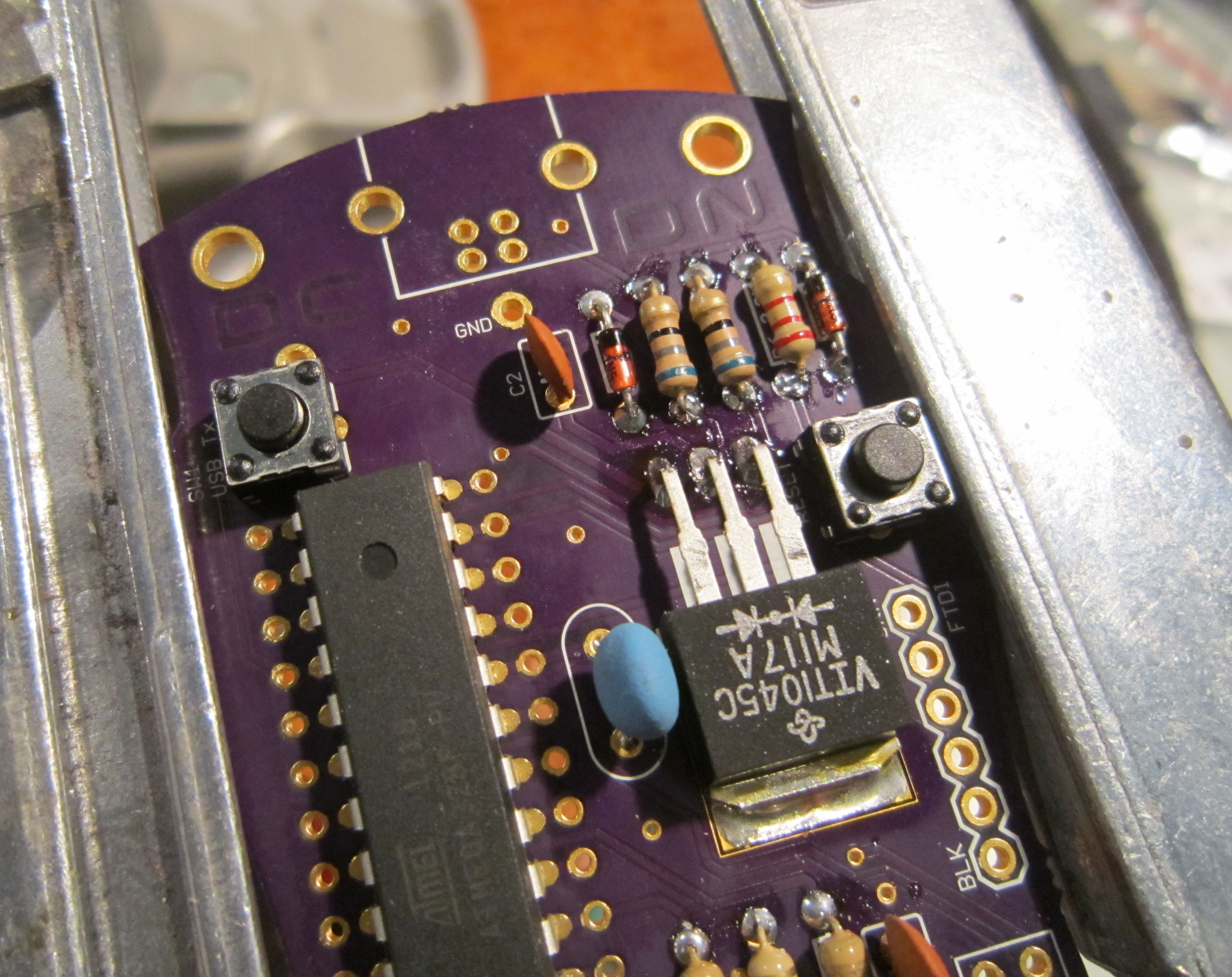
Install the push button momentary switches at SW1 and RESET
Install the infrared receiver module as shown.
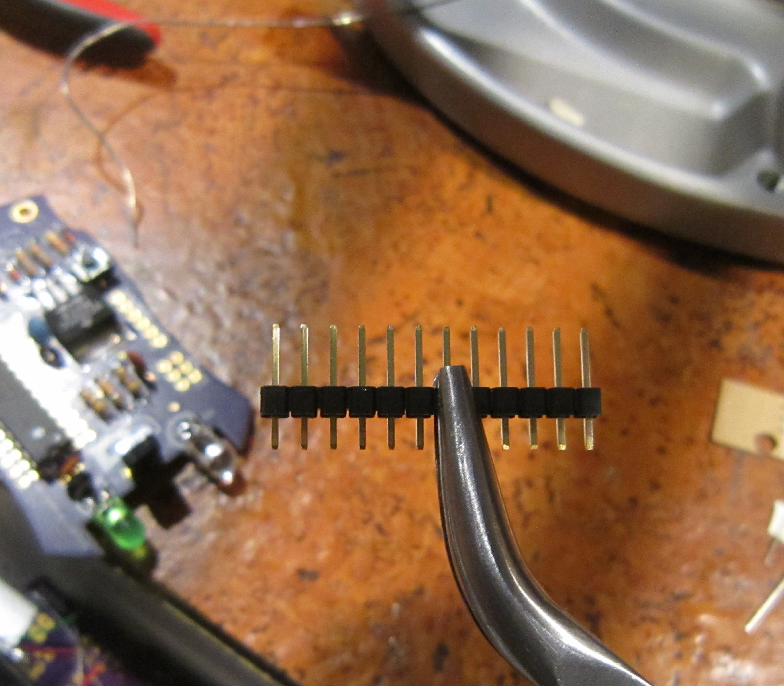
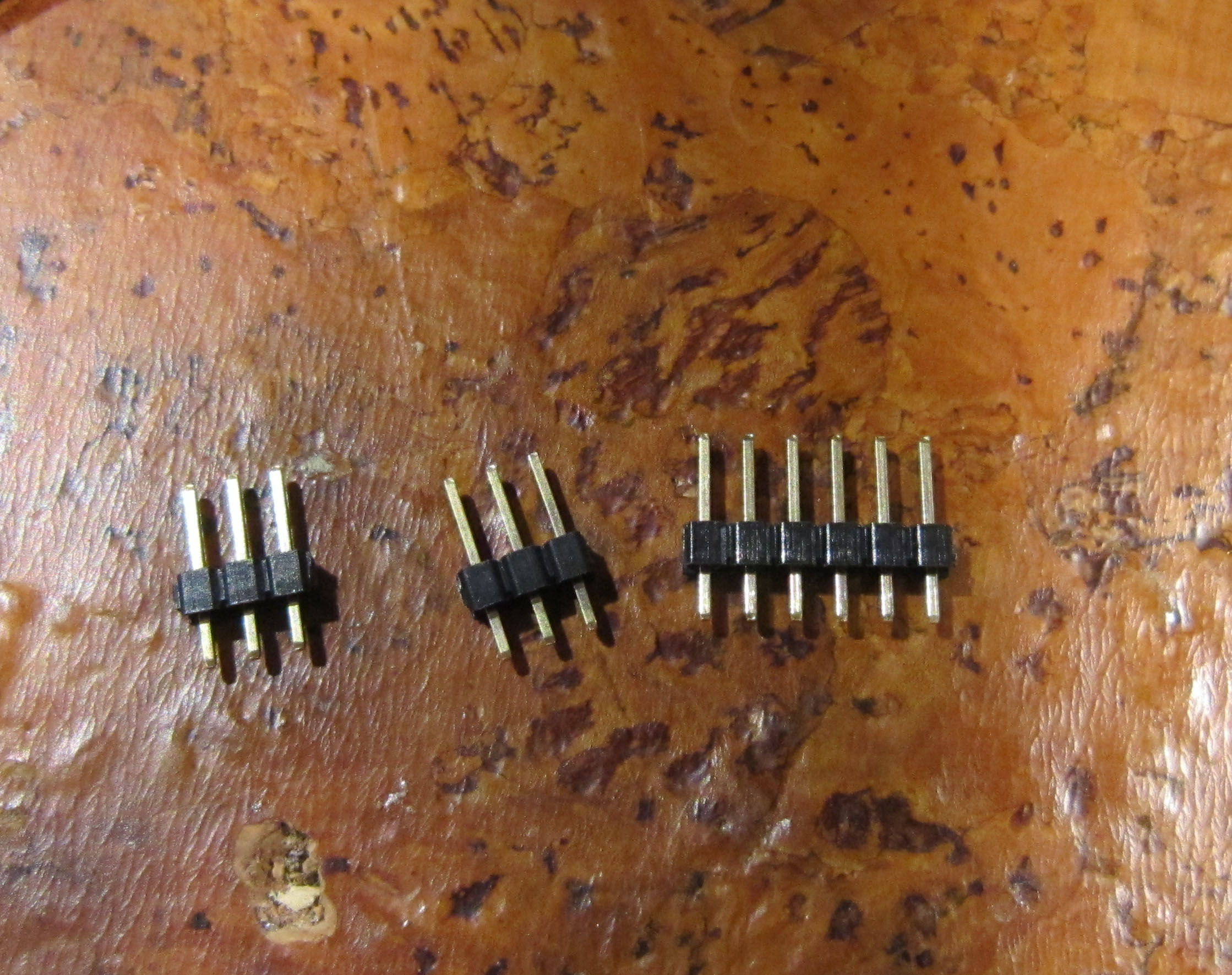
Provided is a 12 pin header, which will be broken in half to get the 6 pin FTDI header.
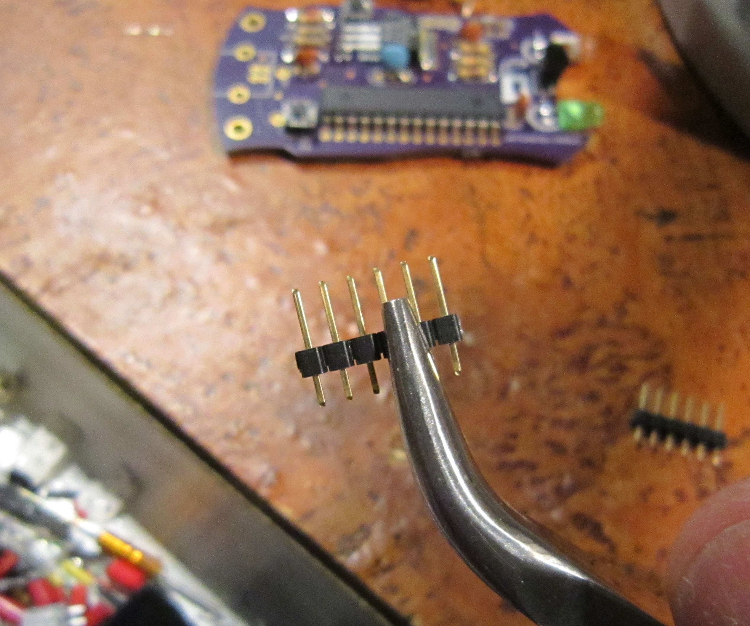
With one of the 6 pin halves, break in half to get two 3 pin headers which will be used for the ICSP header.

Install the headers as shown, soldering on the underside of the board.
Provided is a USB interface, which lets your badge emulate a HID keyboard when you press the USB Tx button.
Install as shown.
Solder the pins and tabs. The tabs are structural and will require a little more solder to fill in the hole.
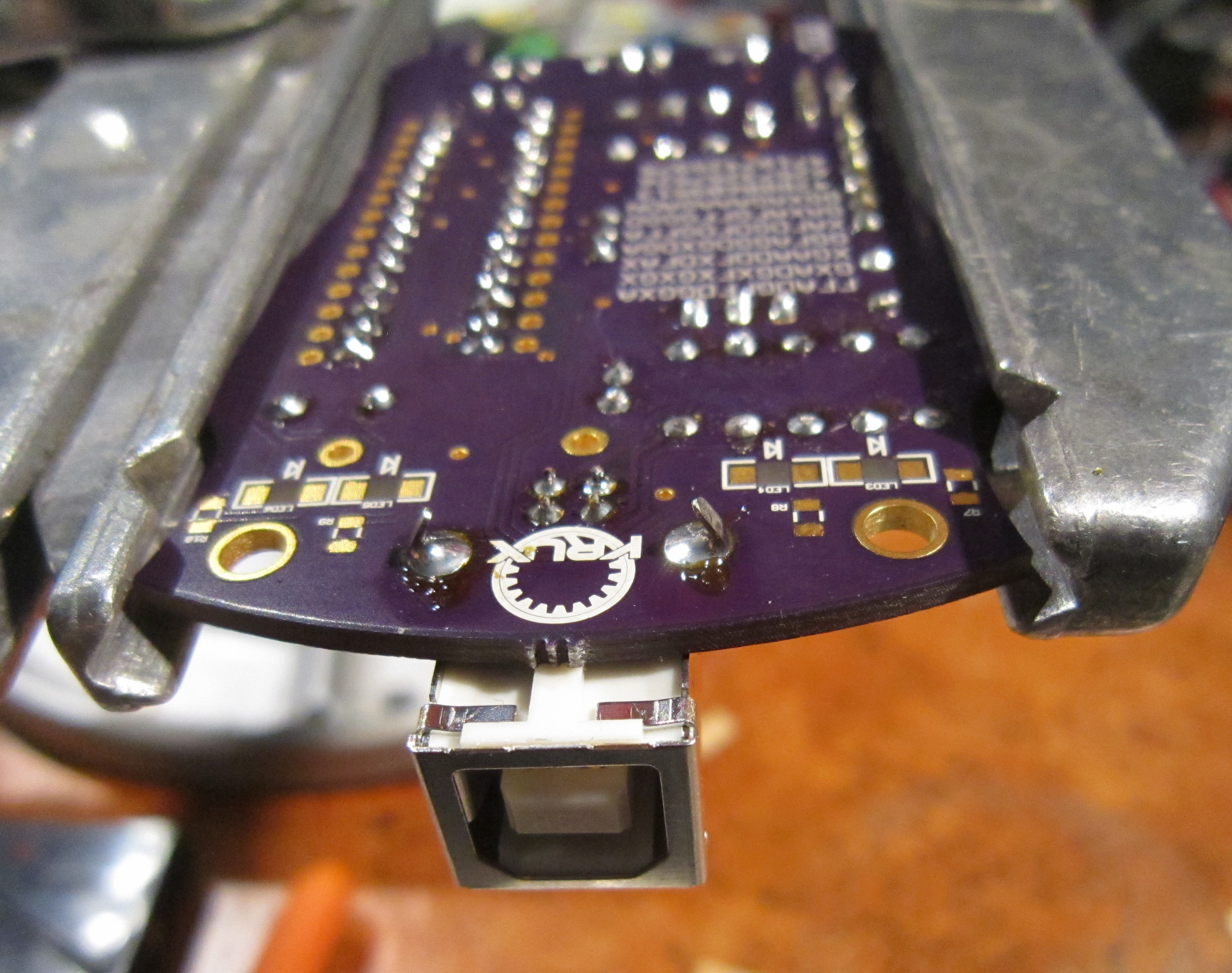
Note before you install the battery holder, this is a good time to take a picture of the cipher text on the back of the board. Decrypt to get extra stuff.
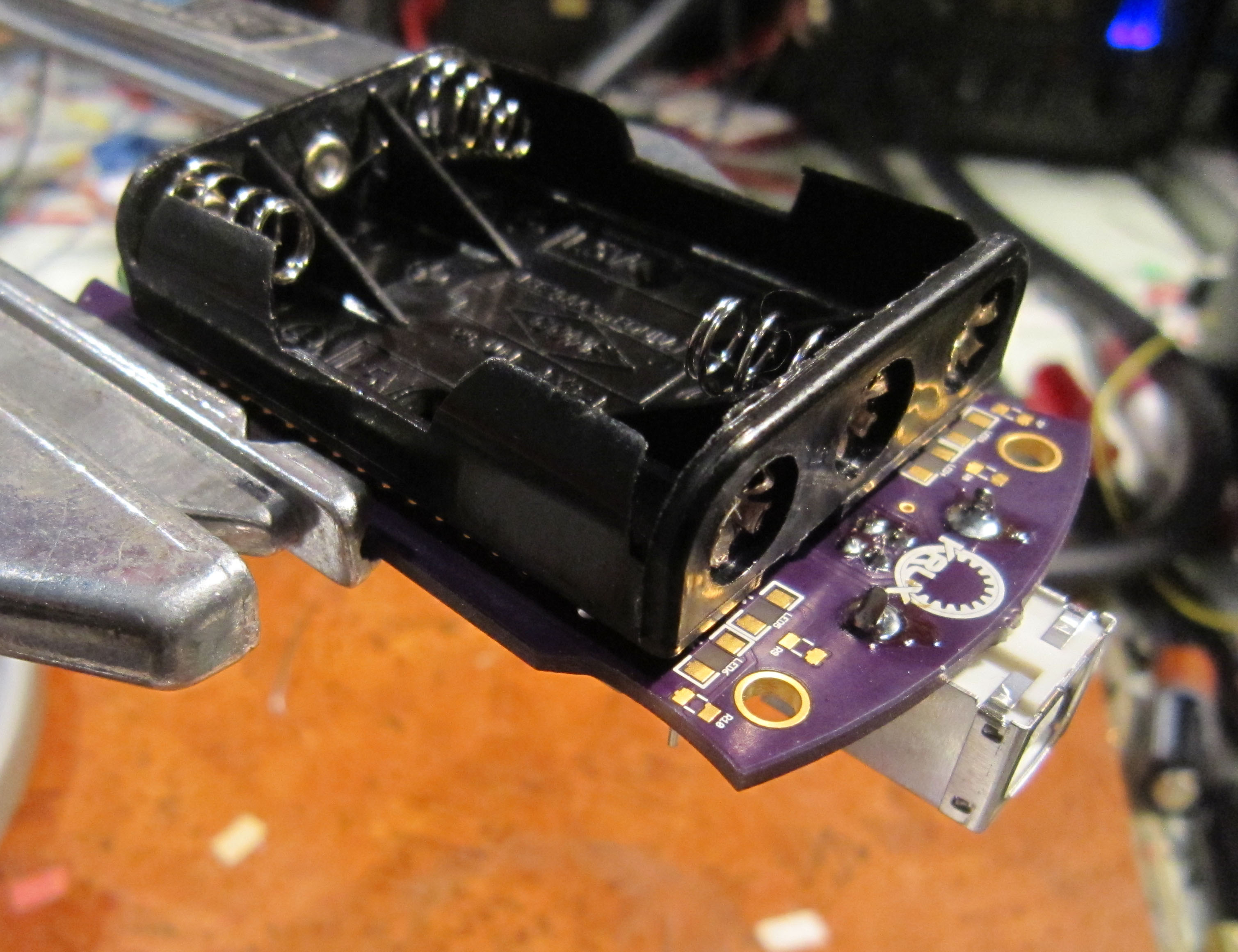
Now you can install the battery holder. The battery holder is soldered in place from the top side of the board.
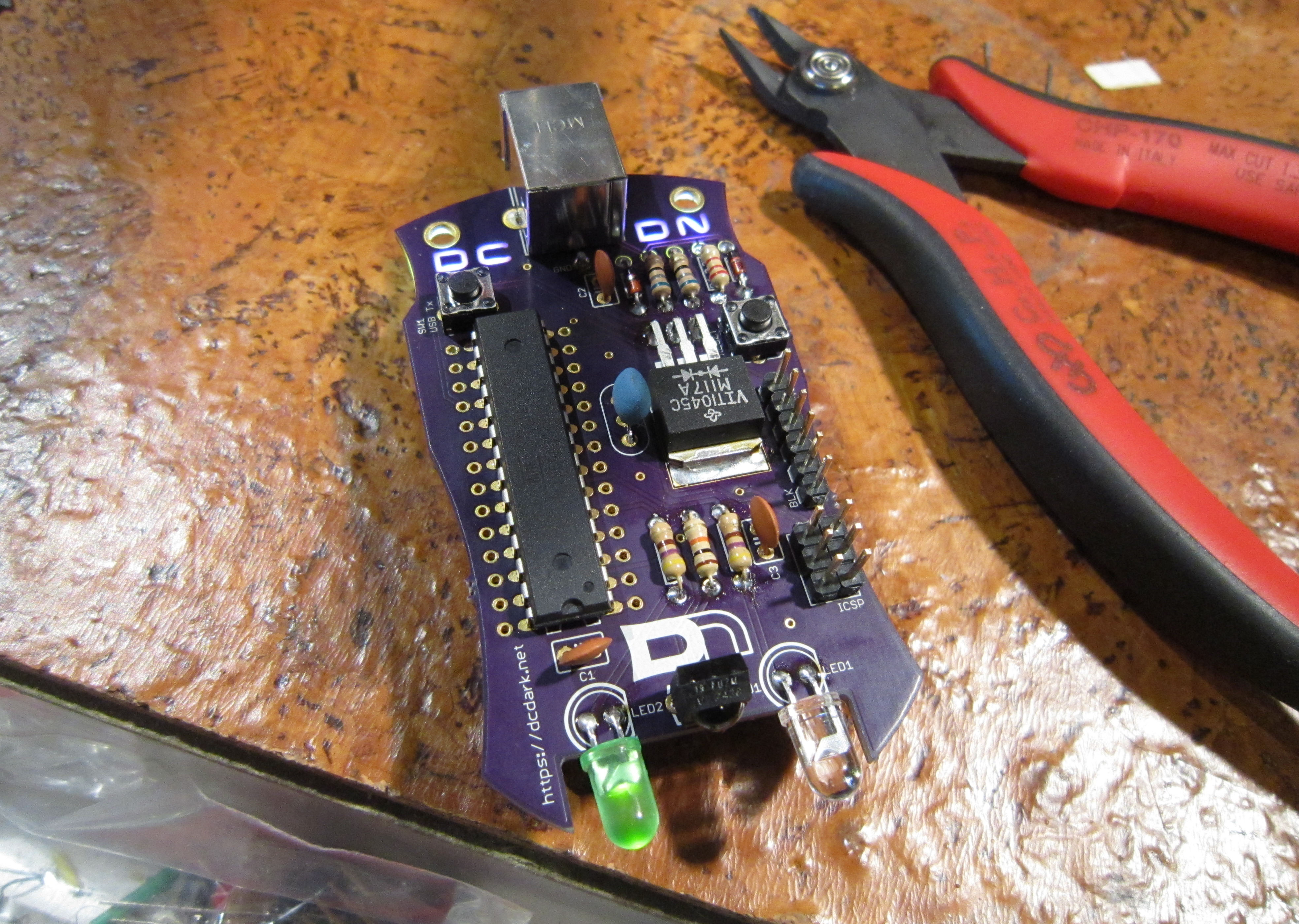
Once you have soldered the battery holder in place, your DEFCON Darknet ID badge is complete. Pair with other Darknet Agents, unlock the badge's secrets, and hack your badge to be even more awesome.
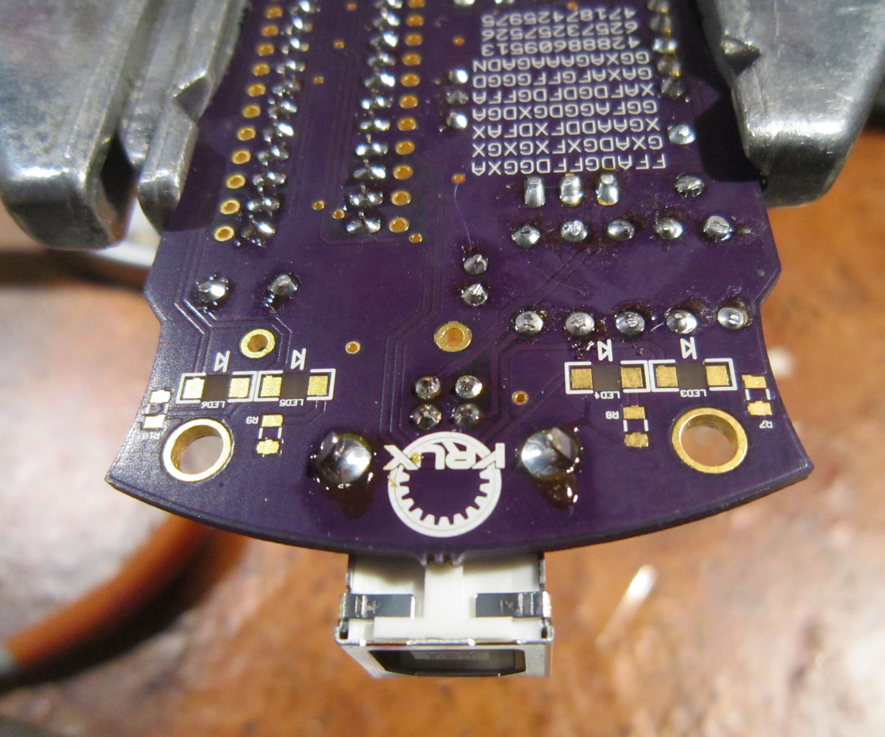
Though not included with the kit, there are SMD pads to install surface mount LEDs to the underside of the board. The LEDs are installed so they shine through the board to light the D C D N letters which have been masked out in the copper layer.
In order to solder the SMD components you will need to desolder your battery holder.
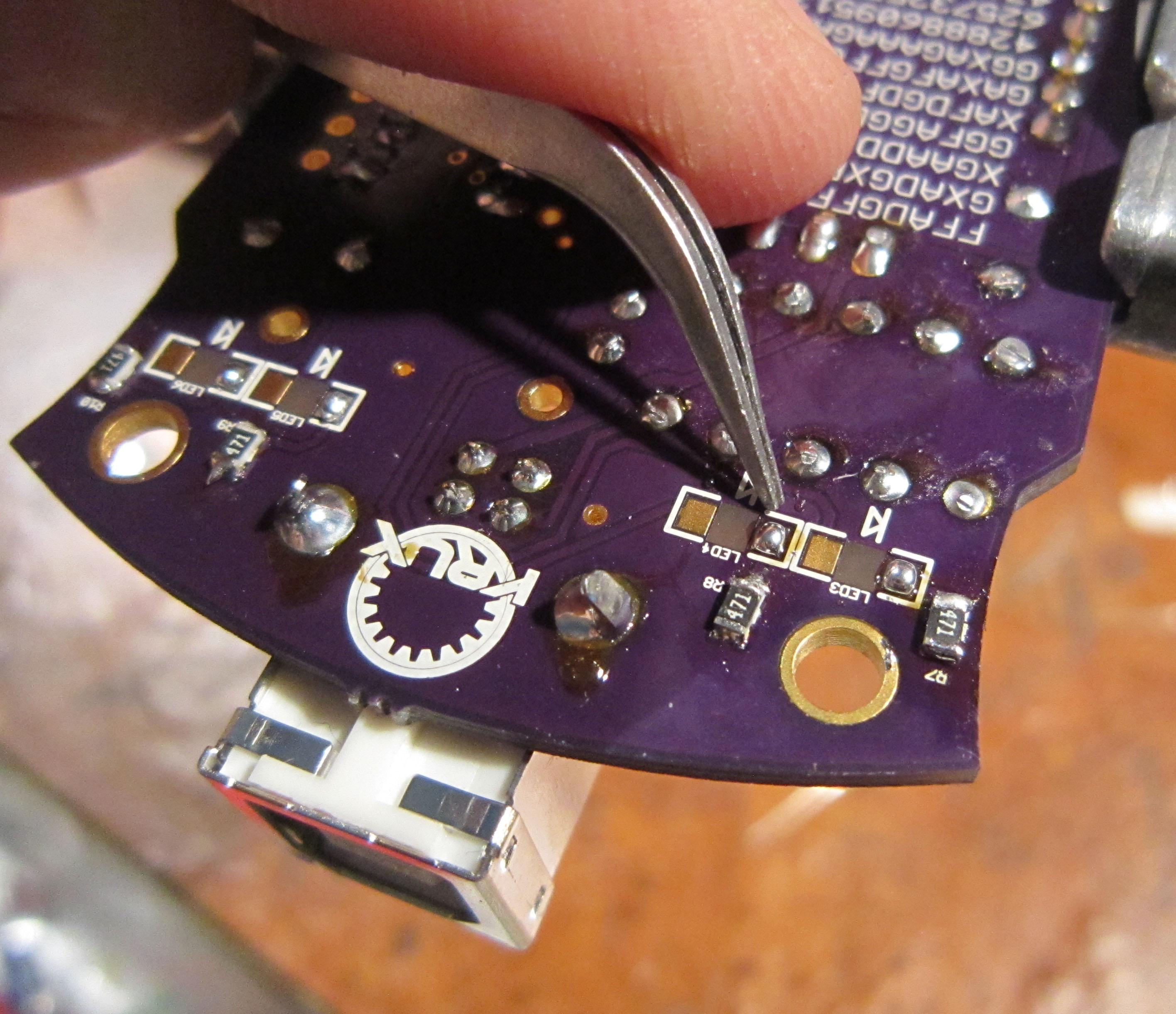
The SMD resistors should be 470 ohm.
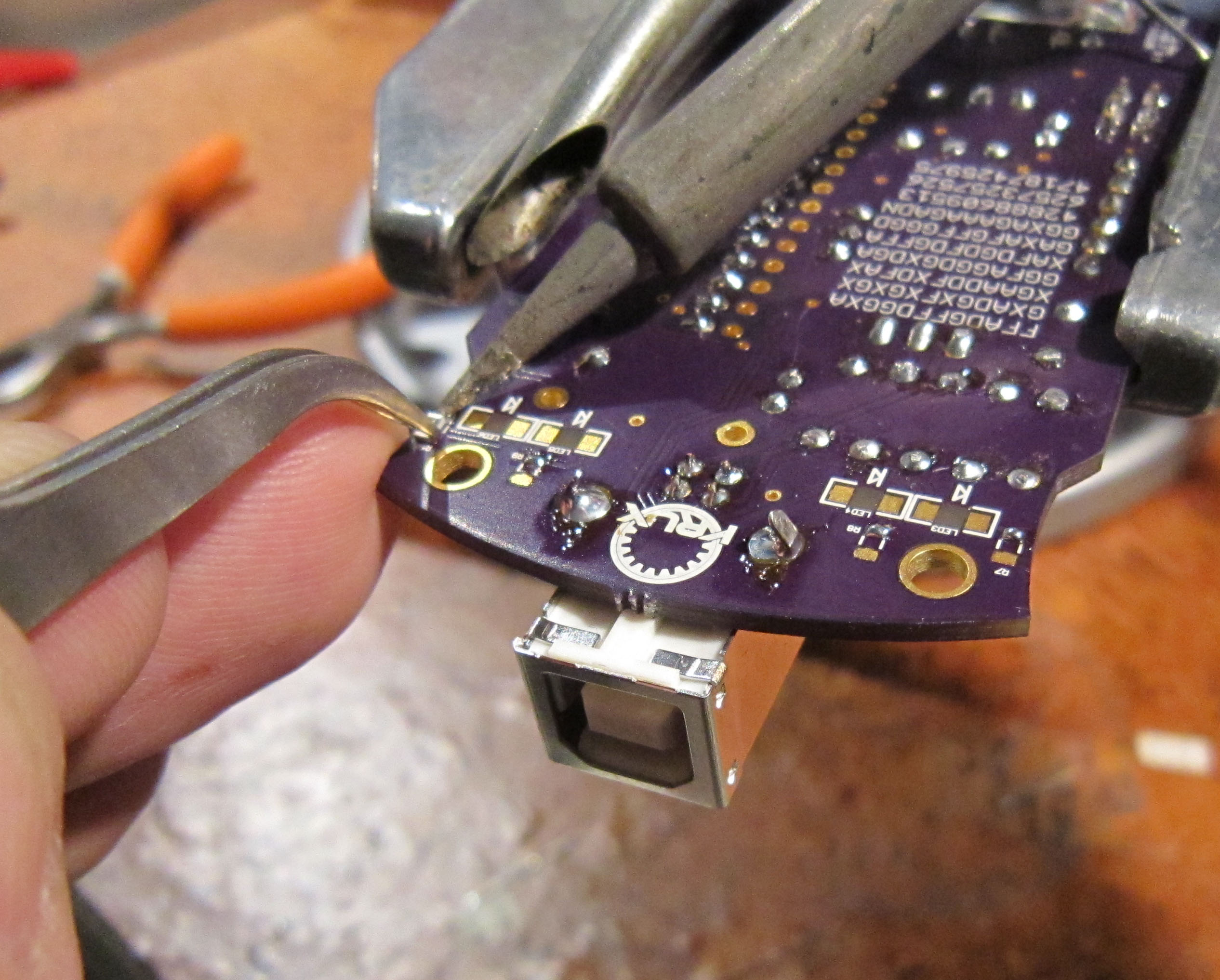
The quick and dirty way to solder SMD components, is to add solder to one of the two SMD pads for each component.
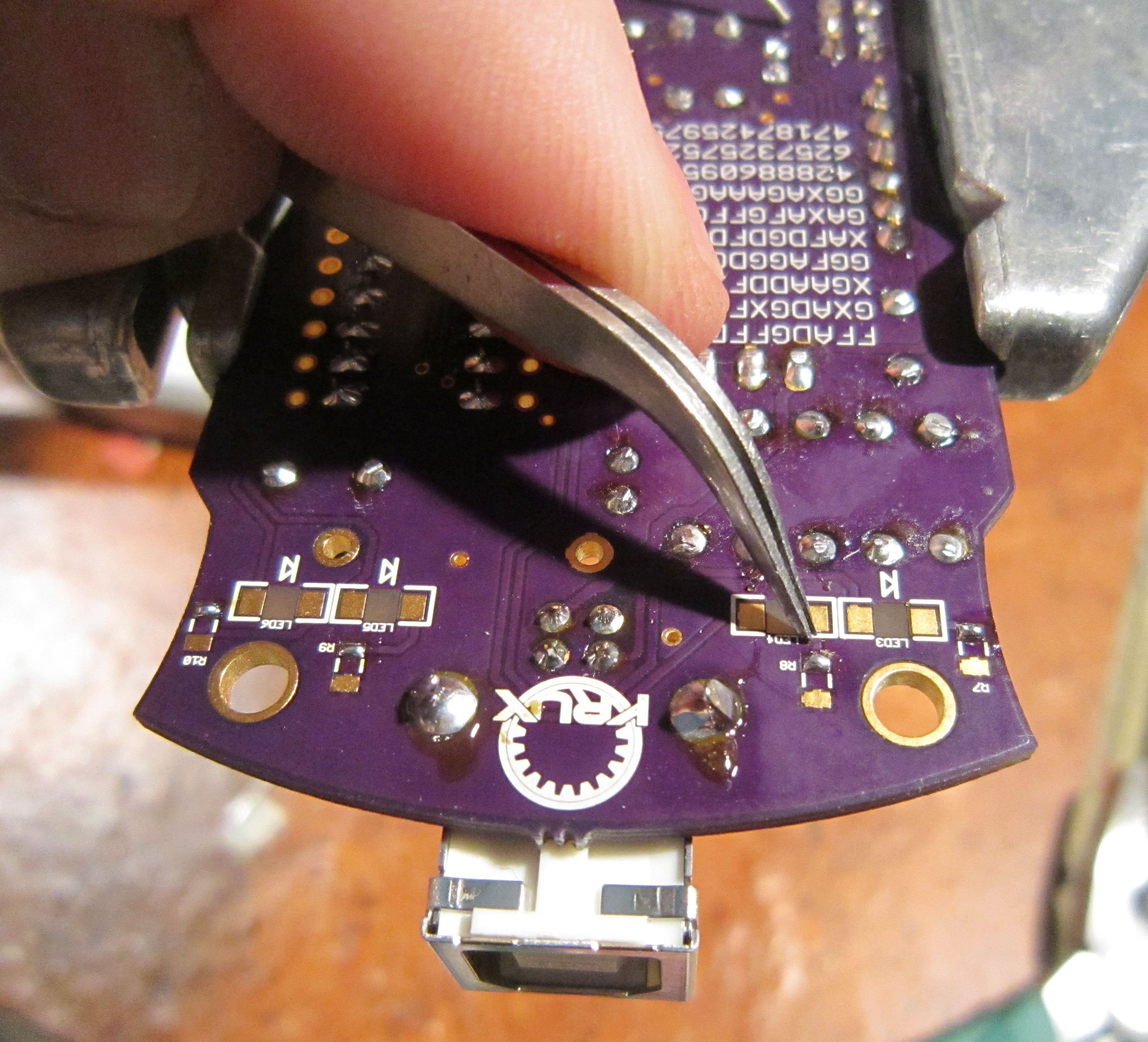
Using tweezers, hold the component in place and use your iron to remelt the solder, which will then hold your component in place.
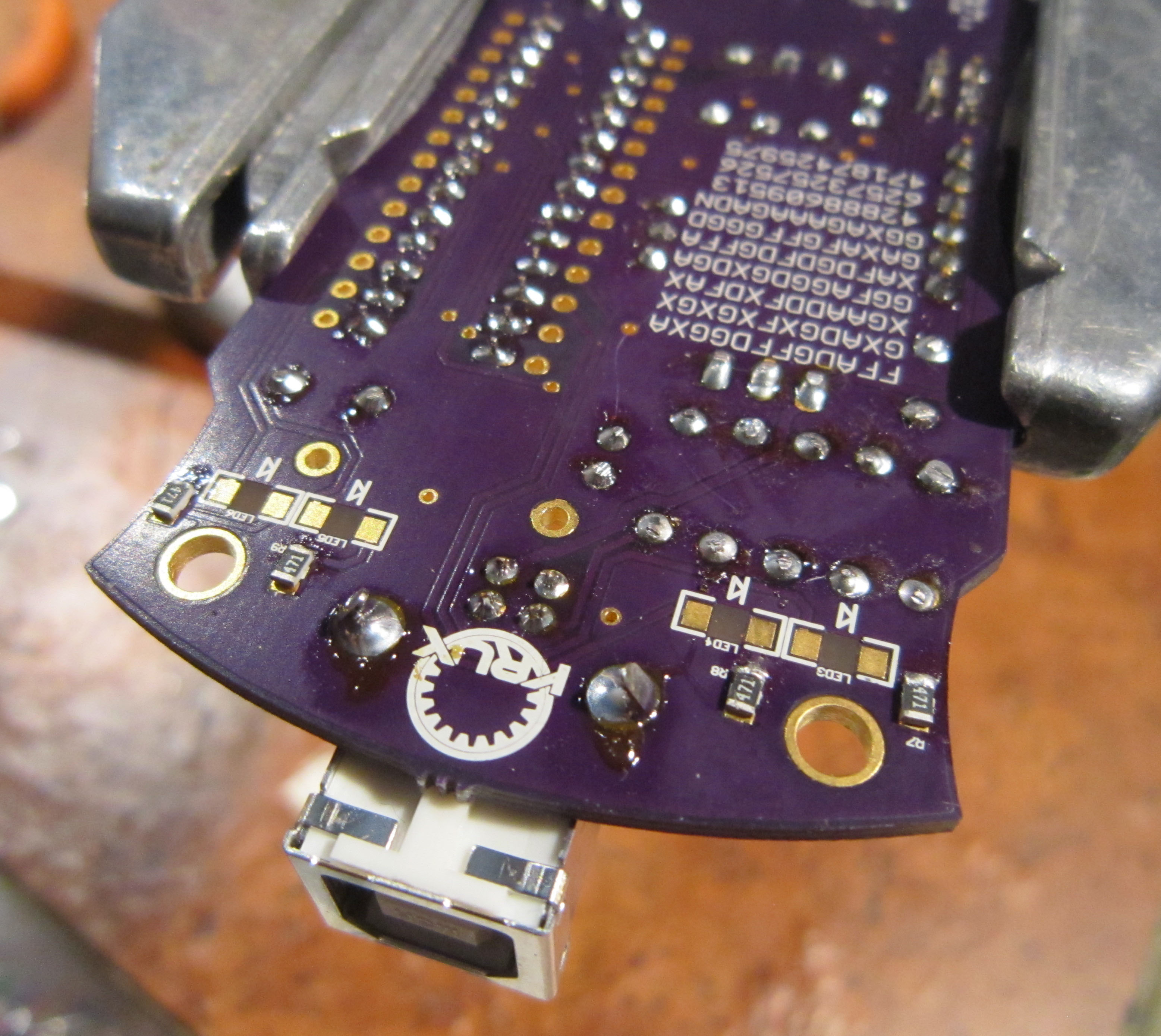
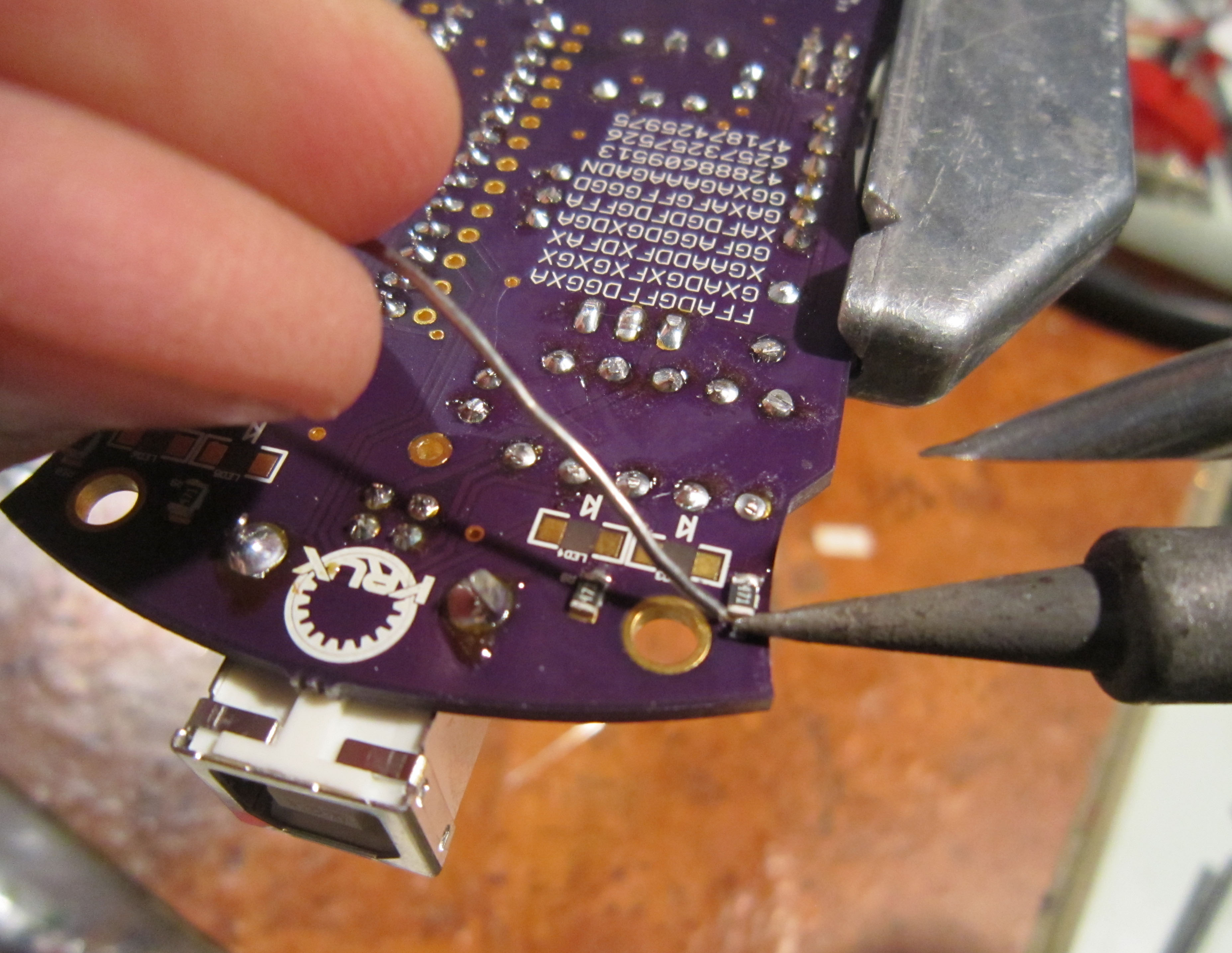
Solder the second pad on each component.
Again, add solder to one of the two SMD pads for each component.
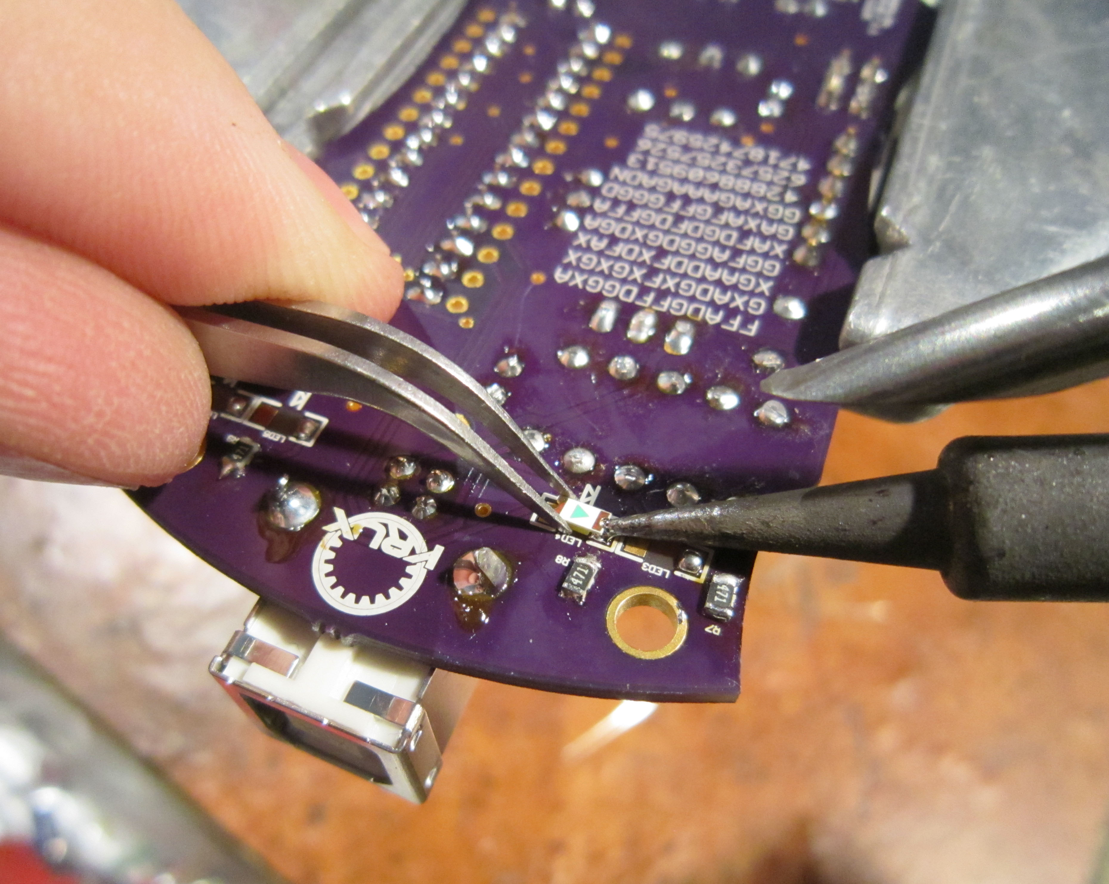
Use tweezers to hold the LED in place in the orientation shown. The Triangle on the underside of the LED will match the silk screen on the board.
Note, you are installing the LEDs upside-down so that they shine through the solder mask and are seen through the front of the board.
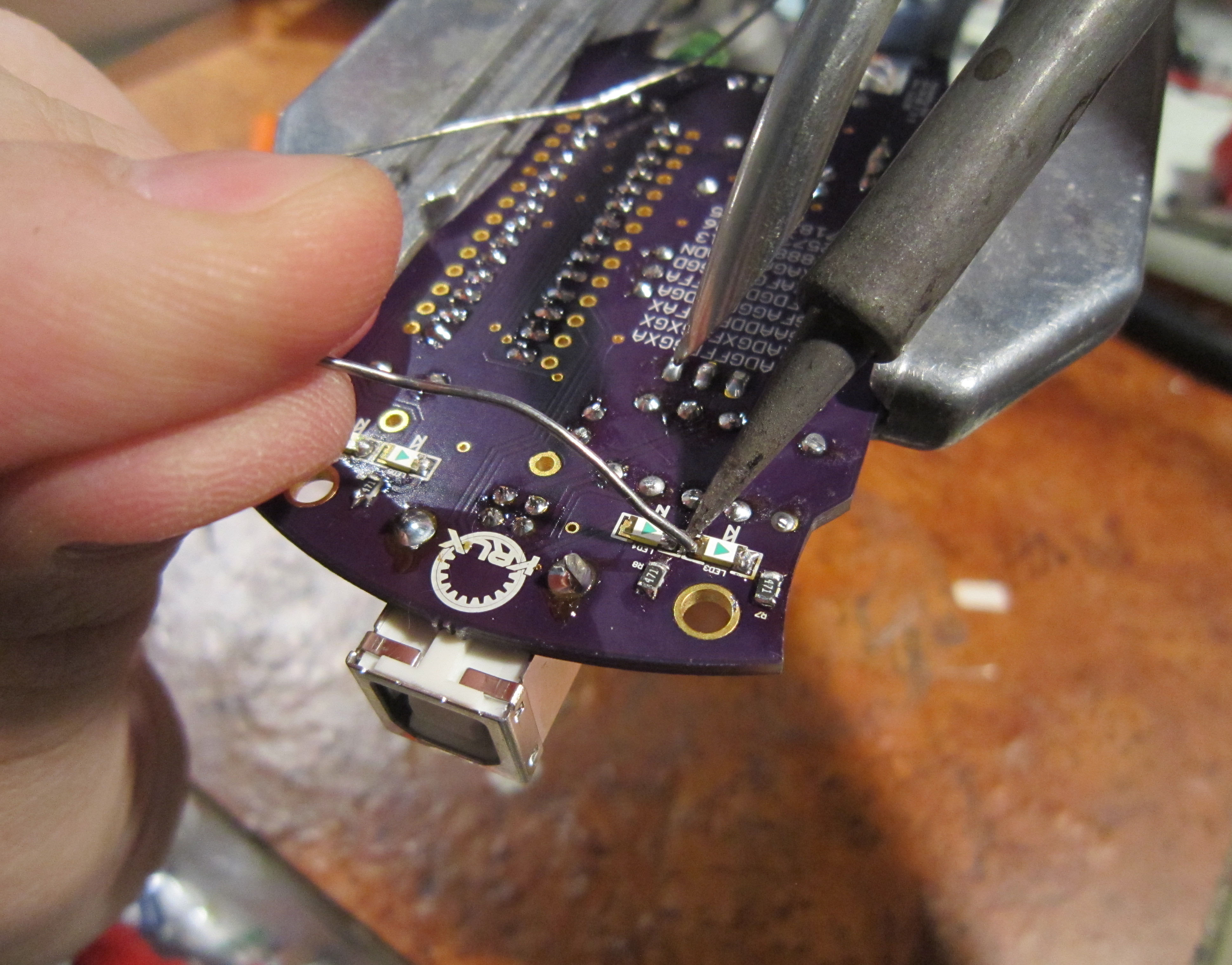
Solder the second pad on each component.
Now your DEFCON Darknet ID badge is really complete. At least until you hack it. Show us what you come up with in the Hardware Hacking Village.