SMD Instructions
Step 1.
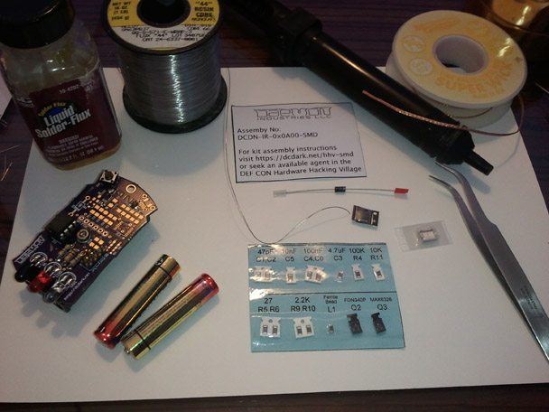
You will need the following tools:
- Temperature controlled soldering iron
- Fine solder
- Flux
- Tip cleaner
- Flush cut diagonal cutters
- Small screw driver
- Tweesers
- Plyers
- Desoldering Braid
- Helping hands
- Scisors
Step 2.
Verify you have the following parts:
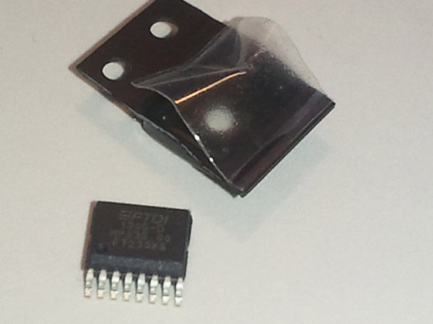
- FTDI chip
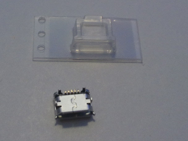
- USB connector
- Diode
- Sheet with SMD components
Step 3.
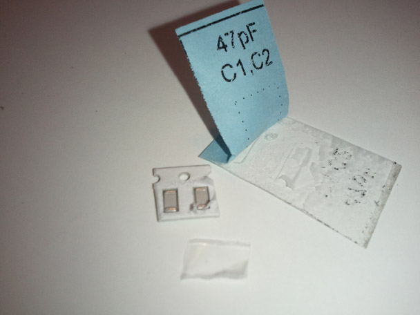
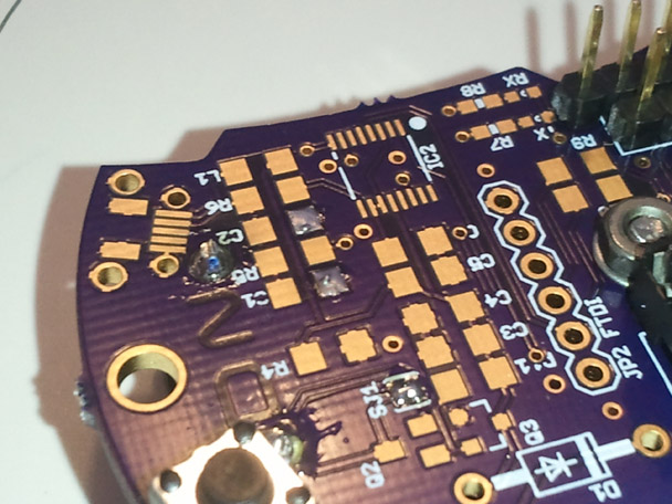
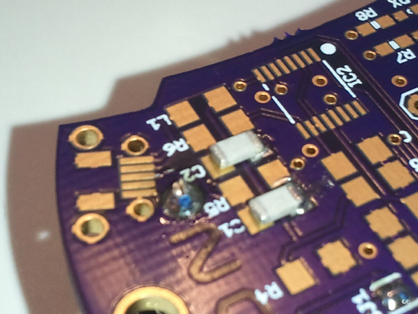
Solder the 47pF capacitors C1 and C2.
Tip: You can easily solder a SMD device by pre-tinning one of the pads, and then heating the pad and part to solder the one side in place. Then once the first pin has been soldered, the other pin or pins can be soldered without the part moving.
C1,C2 47pF
Step 4.
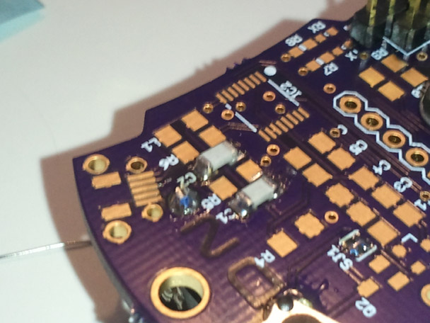
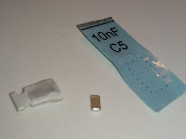
Solder the 10nF capacitor C5.
C5 10nF
Step 5:
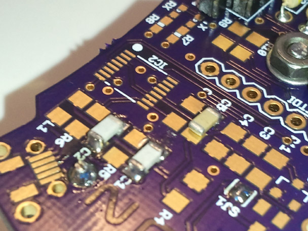
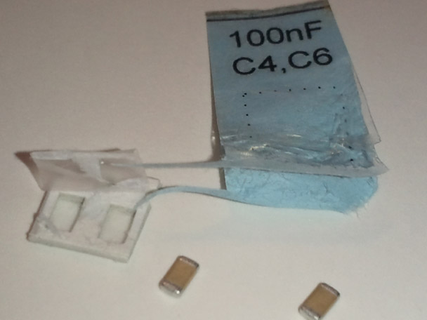
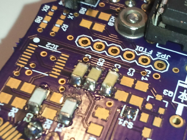
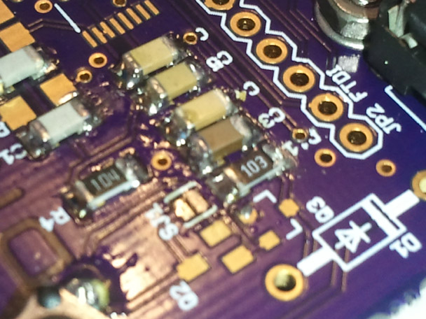
Solder the 100nF capacitors C4 and C6.
Note there is an error in the silk screen, so the marking for C6 has a via. However the parts on the board are in numeric order, C6 is next to C5.
C4,C6 100nF
Step 6:
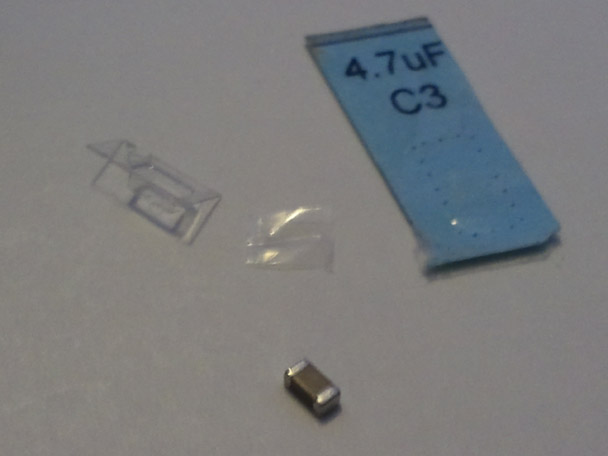
Solder the 4.7uF capacitor C3.
C3 4.7uF
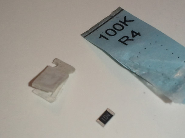
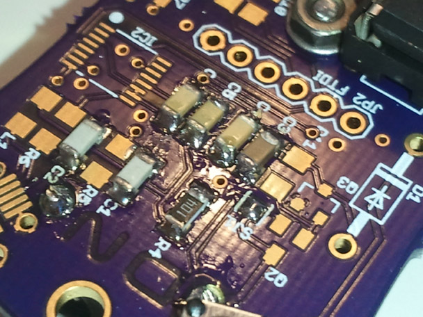
Step 7:
Solder the 100K ohm resistor R4. This part also has a flaw in the silk screen. It's the part next to Q3.
R4 100K ohm
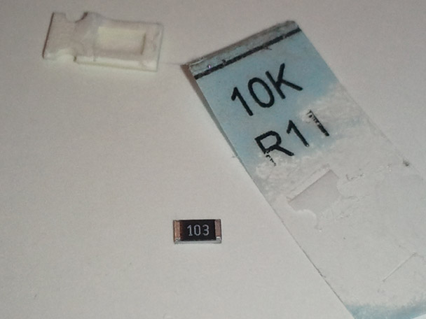
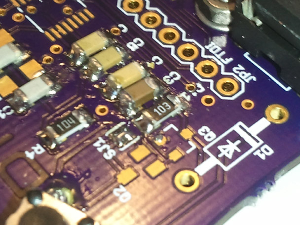
Step 8:
Solder the 10K ohm resistor R11.
R11 10K ohm
Step 9:
If you had previously soldered the SMD power protection bypass jumper, unsolder SJ1
Step 10:
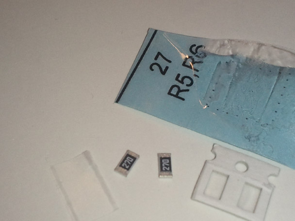
Solder the 27 ohm resistors R5 and R6.
R5, R6 27 ohm
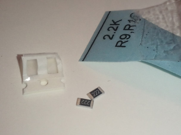
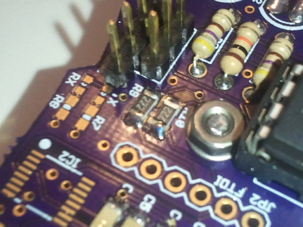
Step 11:
Solder the 2.2K ohm resistors R9 and R10.
R9, R10 2.2K ohm
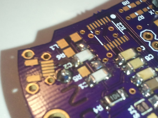
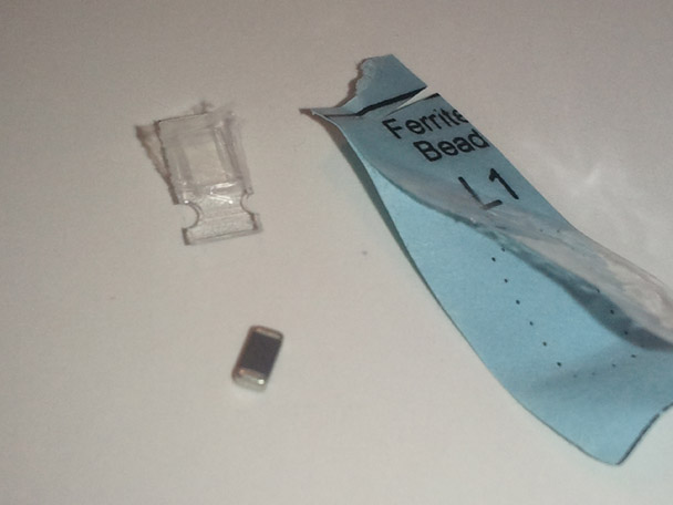
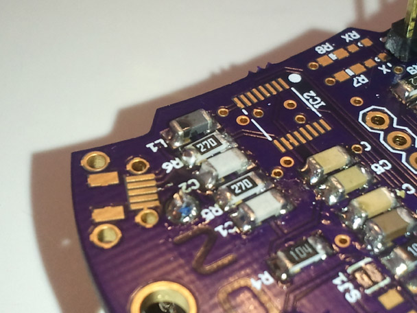
Step 12:
Solder the ferrite bead L1.
L1 Ferrite Bead
Step 13:
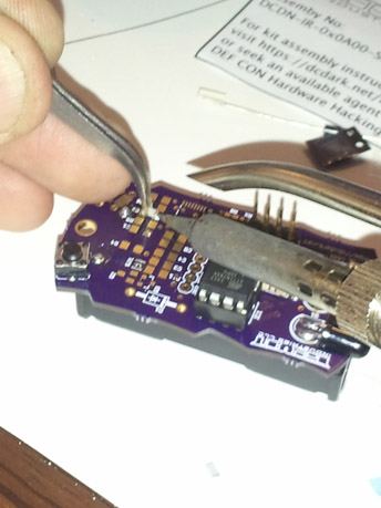
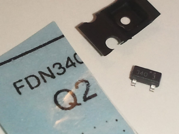
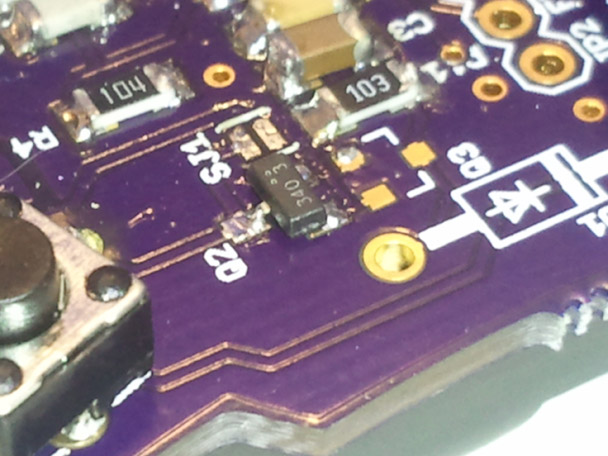
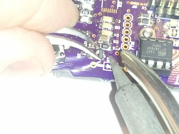
Solder the FDN340P mosfet Q2.
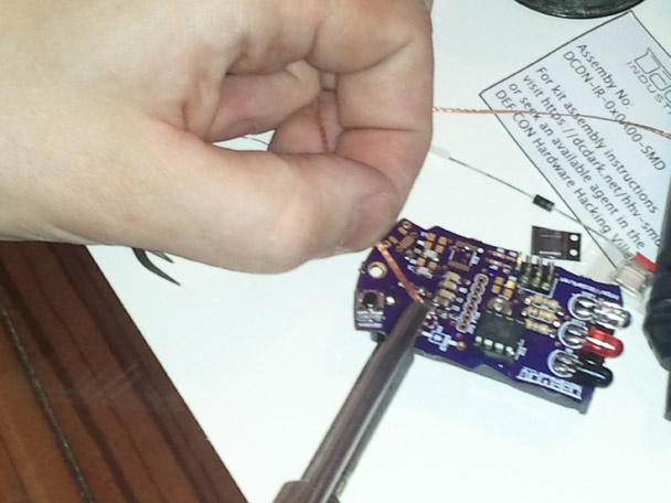
Q2 FDN340P P-Channel Mosfet. This part can be identified by using a mangifying glass or the zoom on your phone camera (as shown) and looking for the numbers 340.
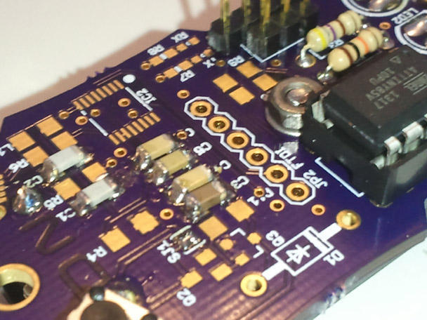
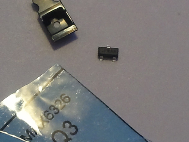
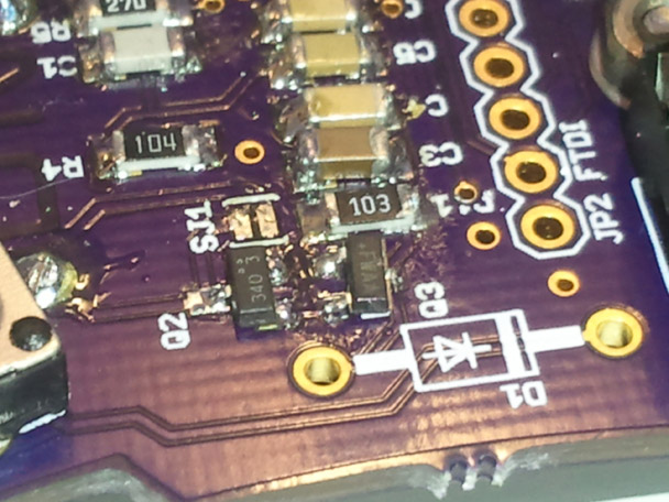
Step 14:
Q3 MAX6328 micro power supervisory circuit. This part can be identified by the text FWAA.
Note: The sheets were printed with MAX6326, but we are using the MAX6328 in this application.
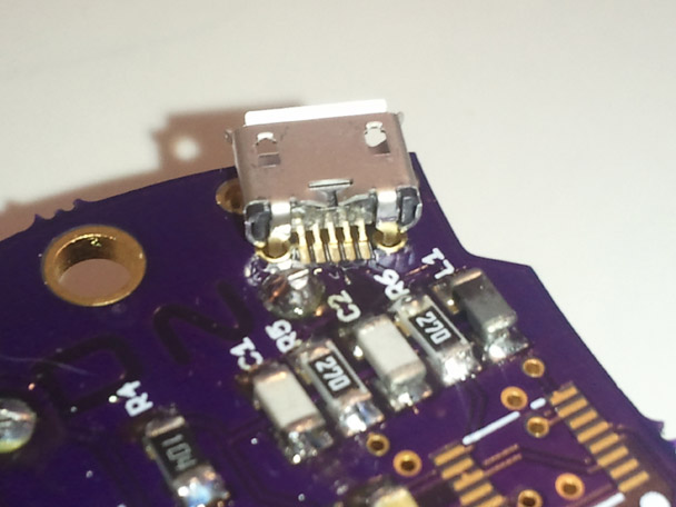
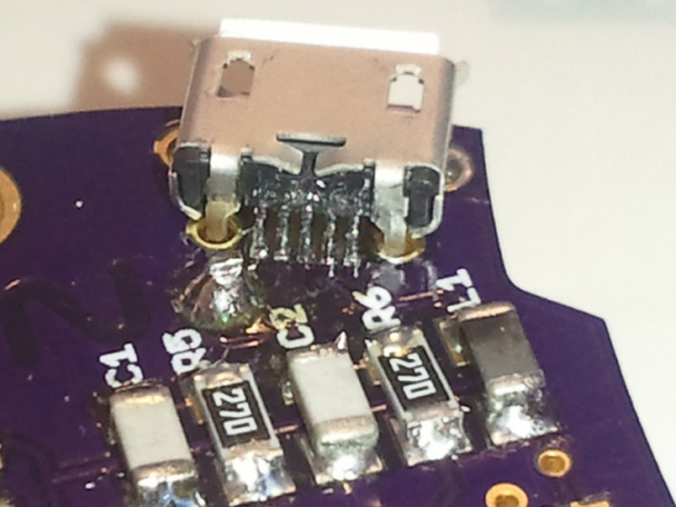
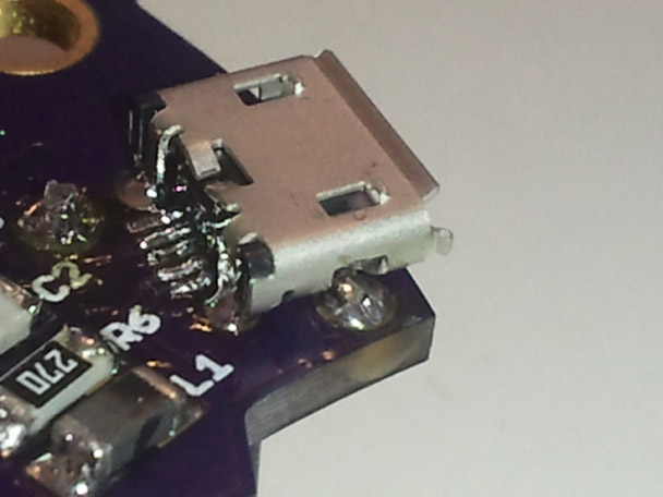
Step 15:
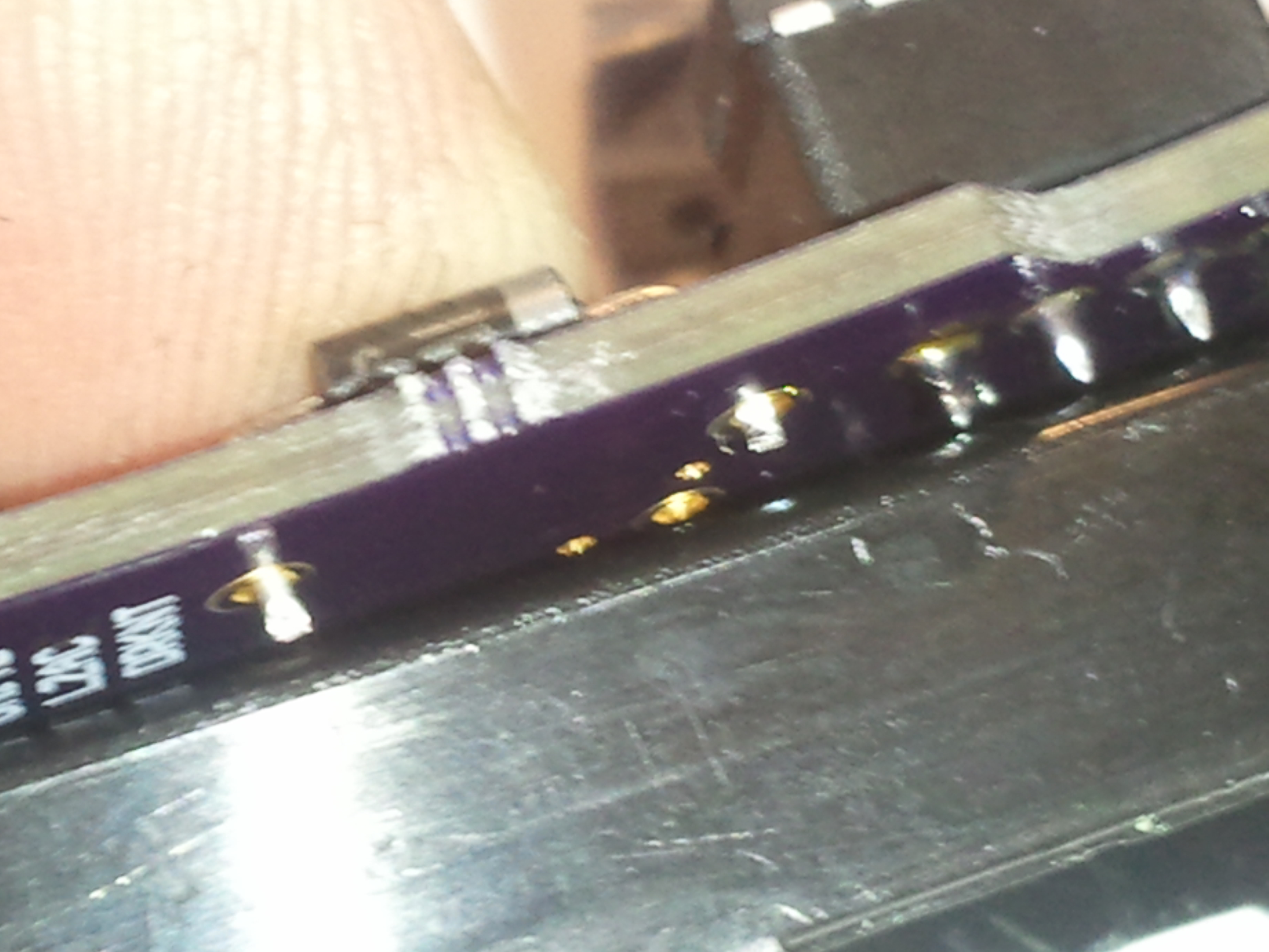
Solder USB connector, first by soldering the leads, and then once in place solder the shield pins to attach structurally to the board.
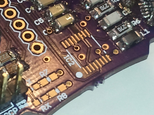
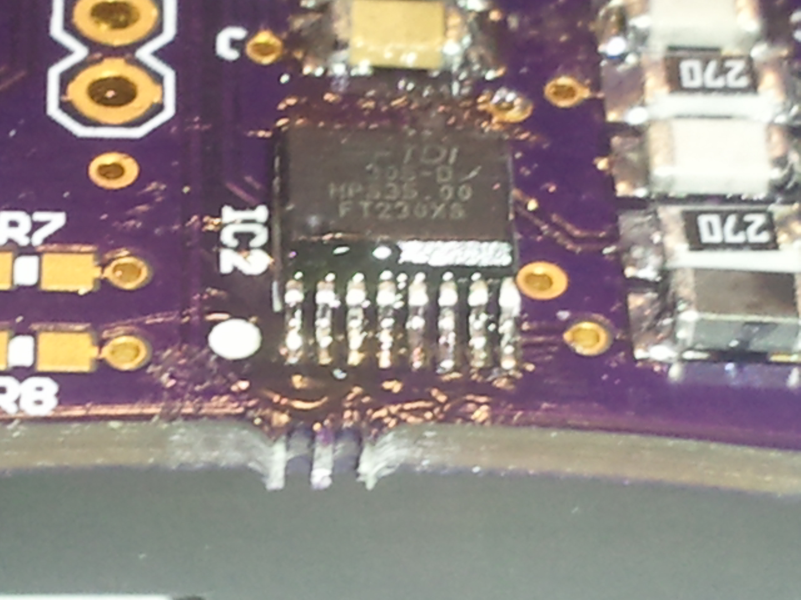
Step 16:
Solder FTDI chip. First start by soldering one corner, then double check the alignement of the chip, and solder the opposing corner pin. Next continue to solder the remaining pins. This part is tricky to solder, but you can clean up any excess solder and bridges pins using solder wick or a solder sucker.
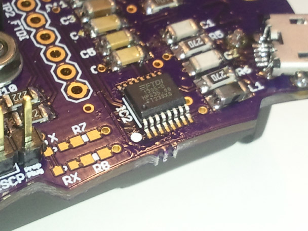
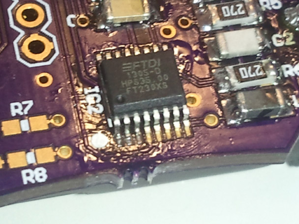
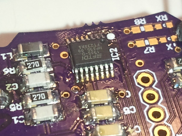
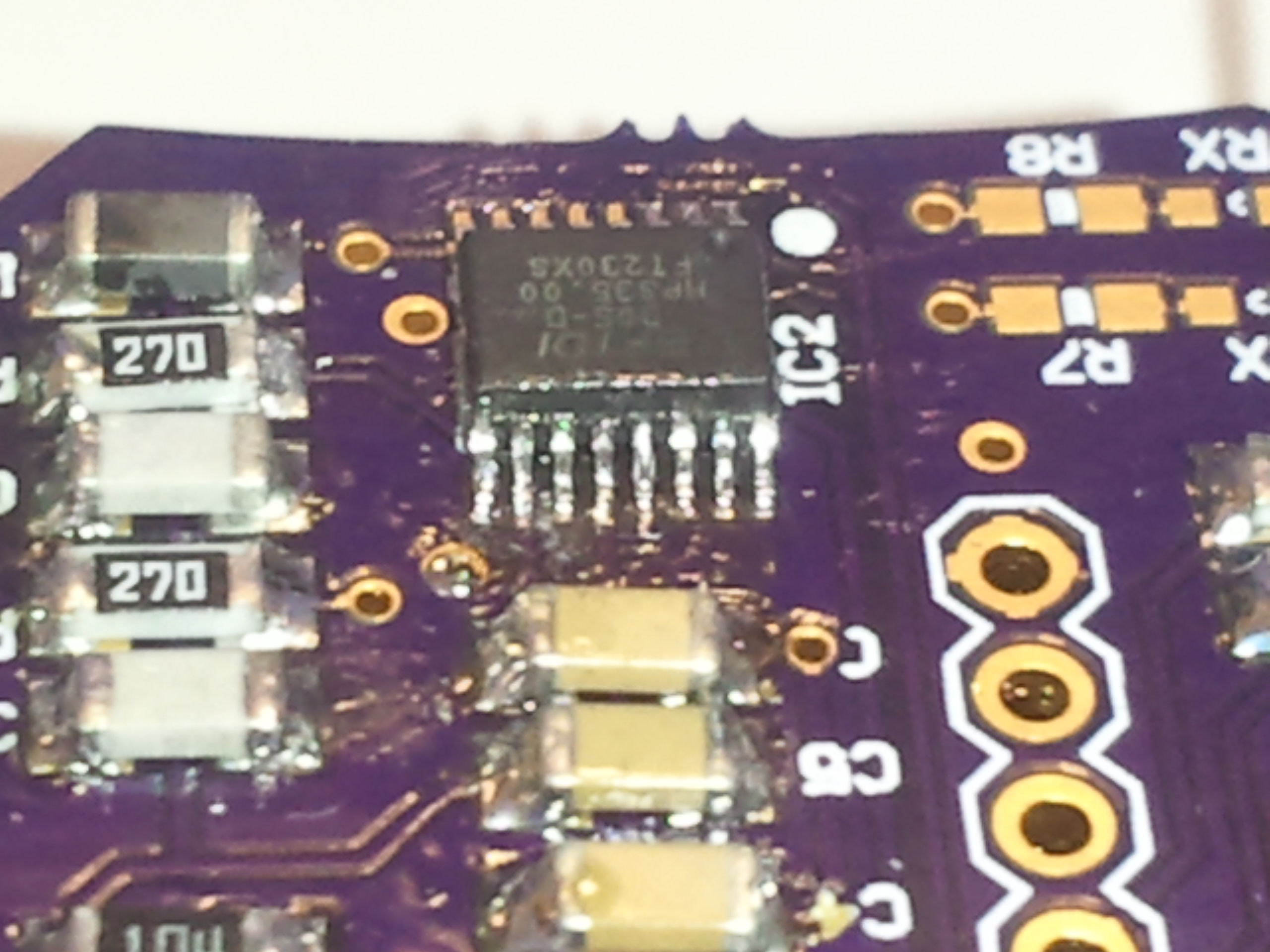
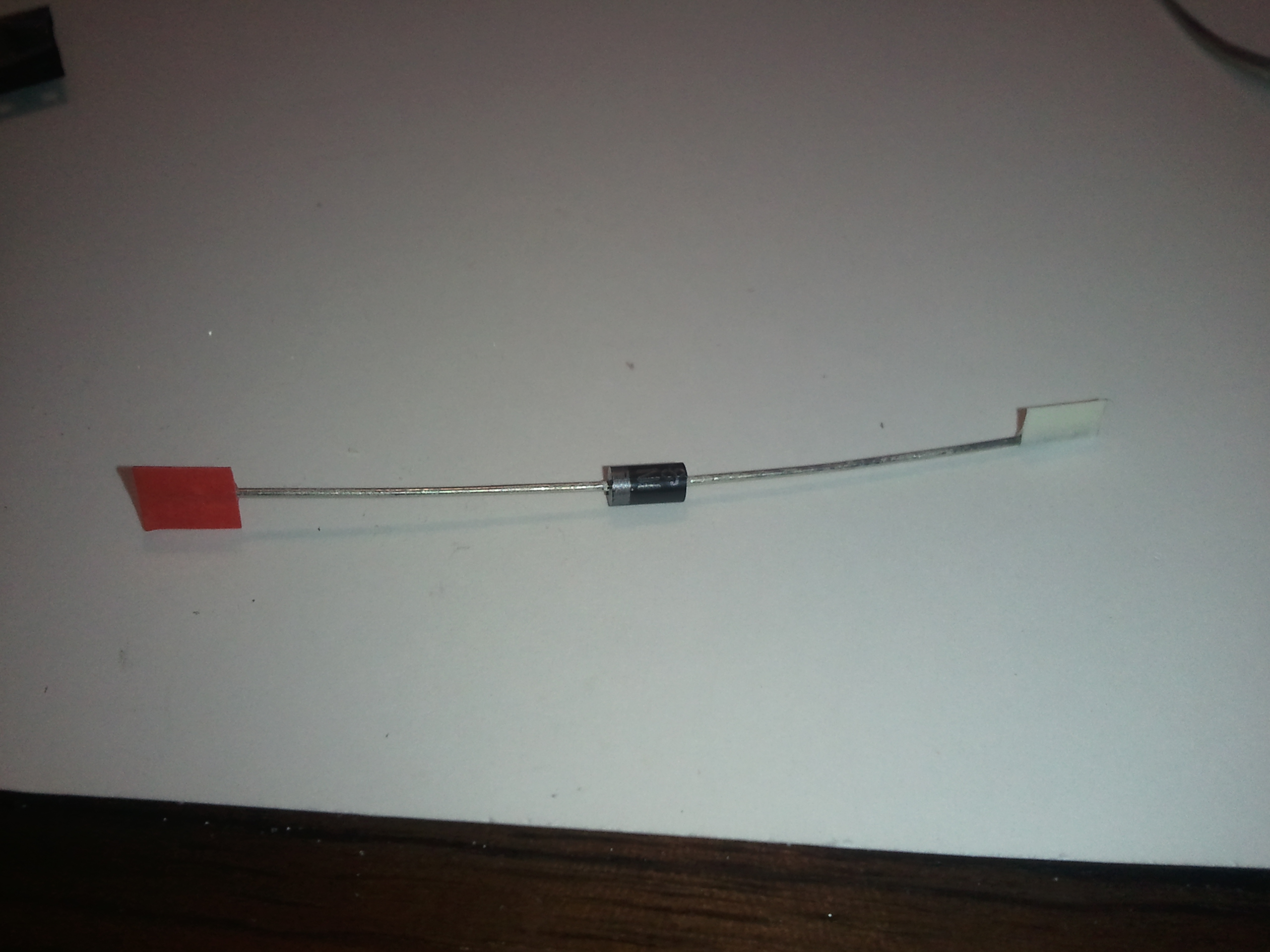
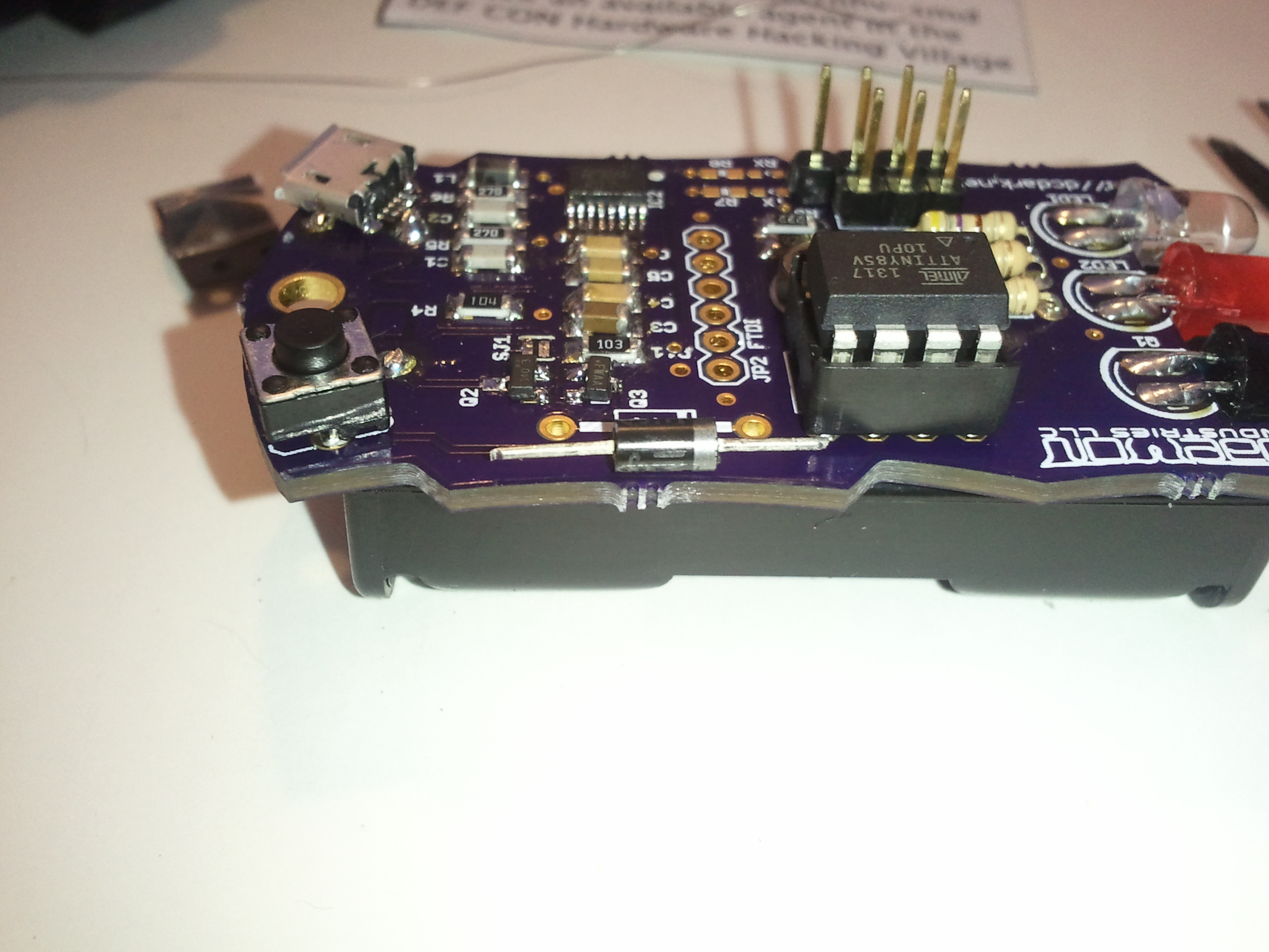
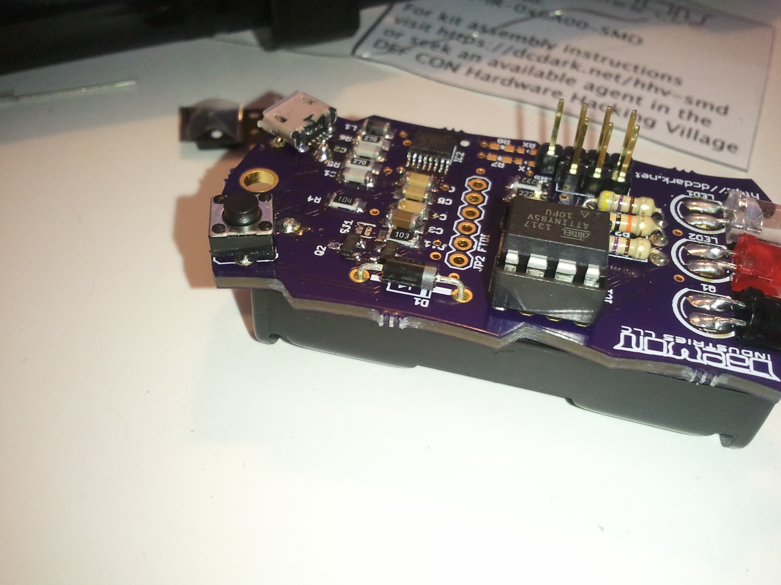
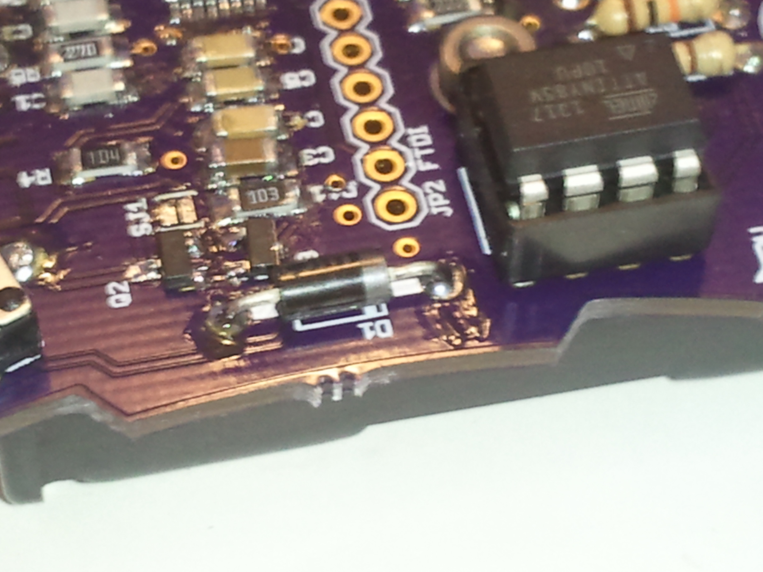
Step 17:
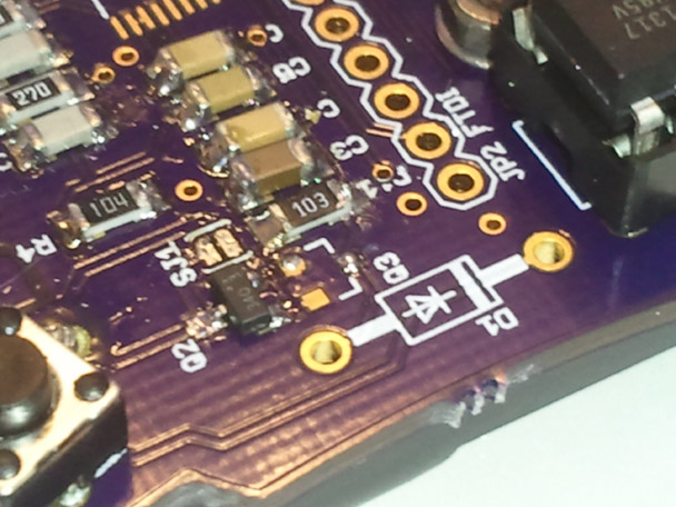
Solder the power protecion diode in place. If you have already soldered the battery pack, cut the leads to length and solder from the top side of the surface after placing the component.
Step 18:
Power on tests
- Install batteries. Verify unit is operational.
- Remove batteries.
- Connect to USB.
- Verify unit powers on.
- Verify serial port is detected, and that serial data is received after pressing the reset button and the chip initializes.
- Verify no voltage is present across the battery terminals. Note: this test is most important, as alkaline batteries will explode if you apply power to them.
You can now safely install the batteries. When unit is plugged into the USB, the power protection circuit will switch off the battery supply, and provide power via the USB. |
