Through Hole Instructions
Step 1.
You will need the following tools:
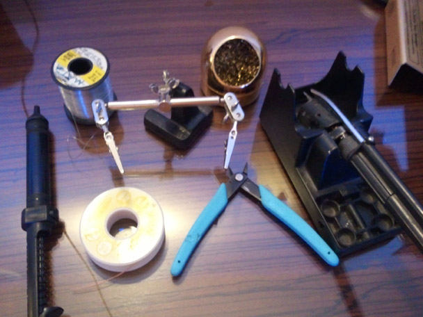
- Temperature controlled soldering iron
- Fine solder
- Flux
- Tip cleaner
- Flush cut diagonal cutters
- Small screw driver
- Tweesers
- Plyers
- Desoldering Braid
- Helping hands
- Scisors
Step 2.
Verify the parts of your kit:
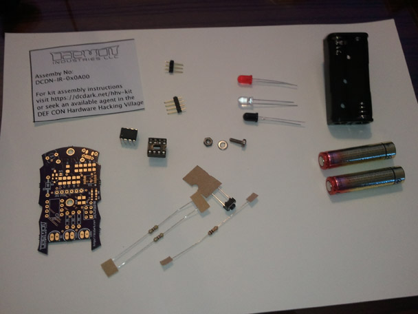
- Instructions sheet
- Circuit board
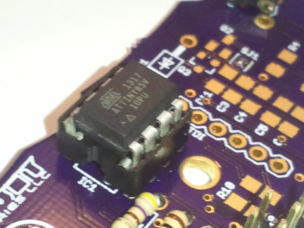
- ATtiny85v
- 8pin socket
- (2) 470 Ohm resistors
- 10k Ohm resistor
- IR LED
- Red LED
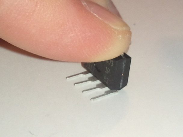
- IR Transistor
- 3 pin header
- 4 pin header
- 2.5mm screw
- 2.5mm washer
- 2.5mm nut
- Battery holder
- (2) AAA batteries
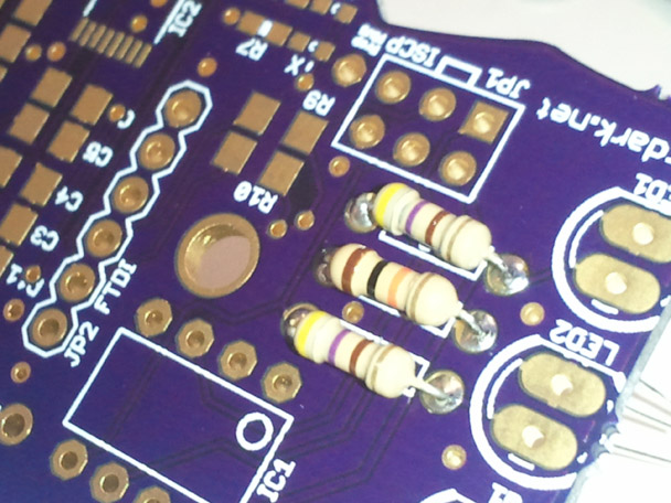
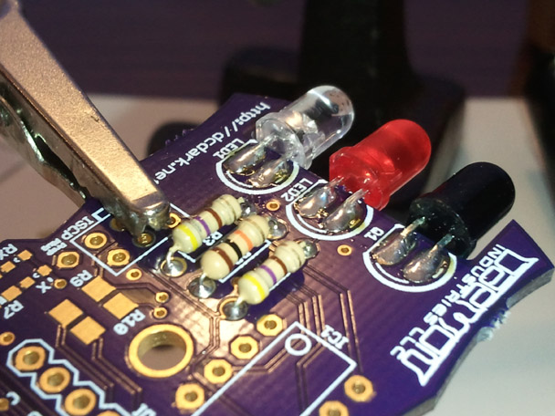
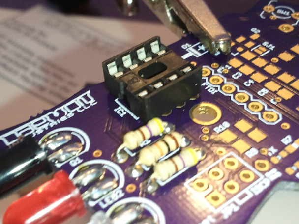
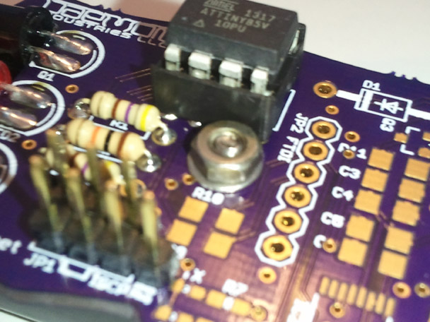
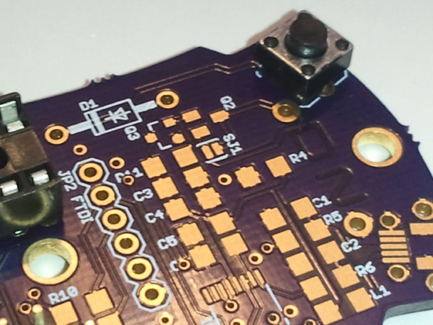
Step 3.
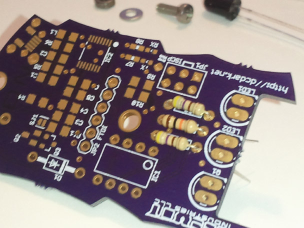
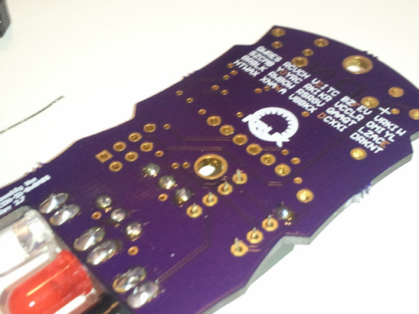
Solder the three resistors.
R1, R3 470 ohm
R2 10k ohm
The 470 ohm resistors have the stripes yellow purple brown gold.
The 10k ohm resistor has the stripes brown black orange gold.
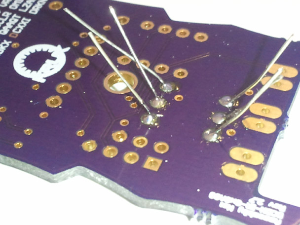
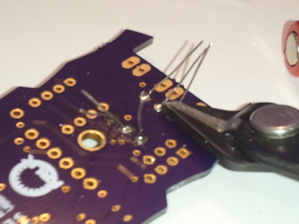
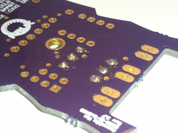
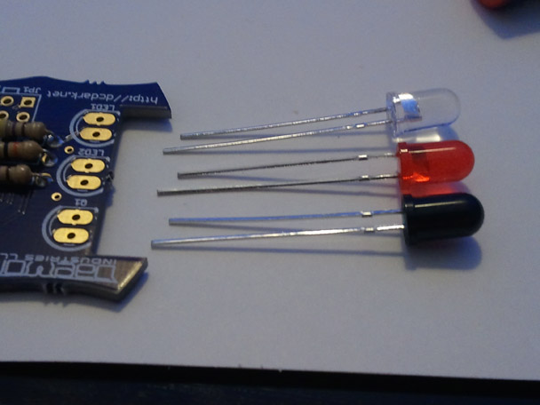
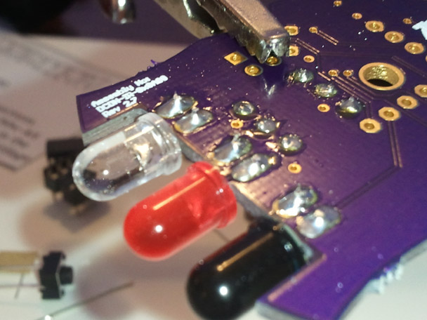
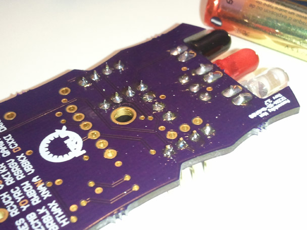
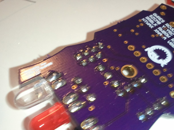
Step 4.
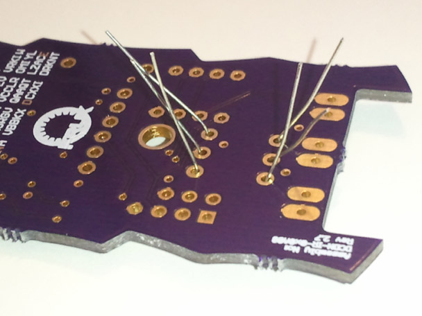
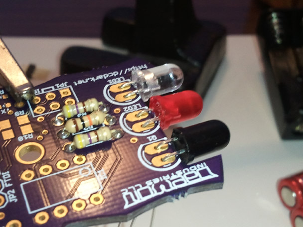
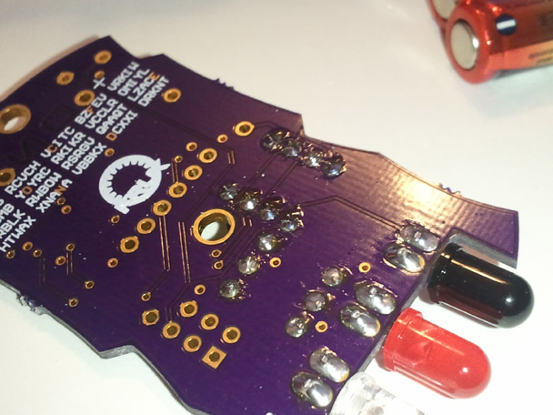
Solder LEDs and IR transistor.
The polarity of the devices is as shown. The flat side should match up with the flat side on the silk screen.. The longer pin is opposite the flat side.
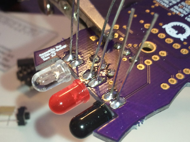
Solder the longer lead first, and then adjust the parts so they are alligned straight. Then solder the opposite side. Finally solder the under side of the board.

Step 5.
Solder the 8 pin socket. It should be orientated so the notch in the socket is on the same side as the pin one indicator on the silk screen.
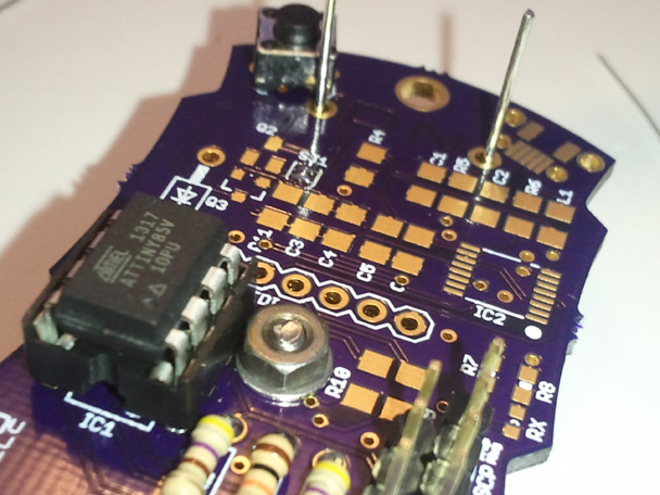
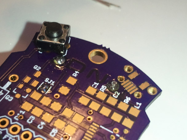
Step 6.
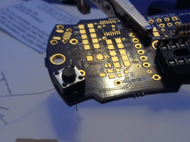
Solder Reset button.
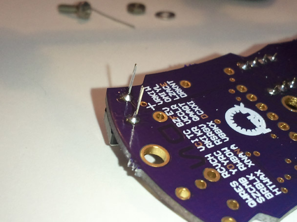

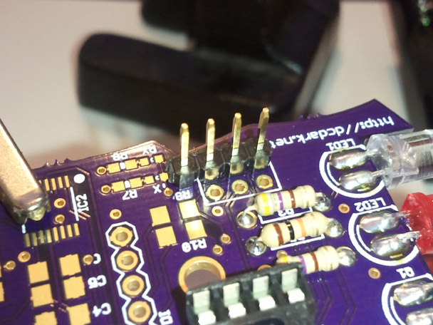
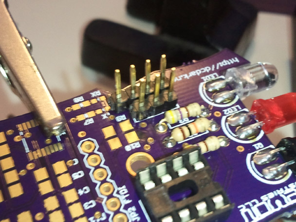
Step 7.
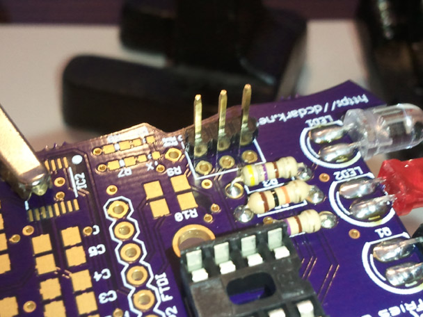
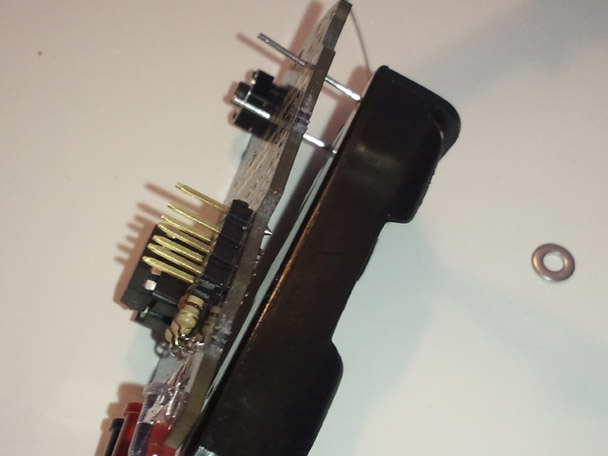
Solder the ISCP programming header. A four pin header and a three pin header are provided.
Note: The fourth pin is optional to allow you to use a Parallax PropPlug to communicate with the board if desired. If you are using the SMD FTDI circuit, then this fourth pin is not needed, and can be trimmed to three pins.
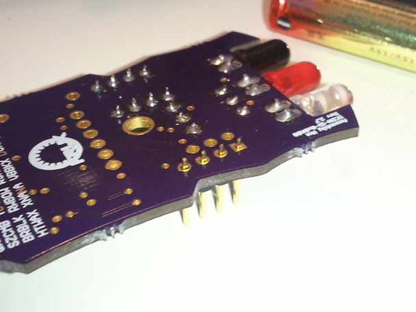
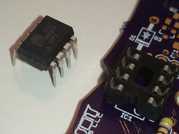
Step 8.
Install Microcontroller. Pin one is orientated toward the notch in the socket, which matches the pin one orientation on the silk screen. You will have to bend the pins in slightly to fit into the socket.
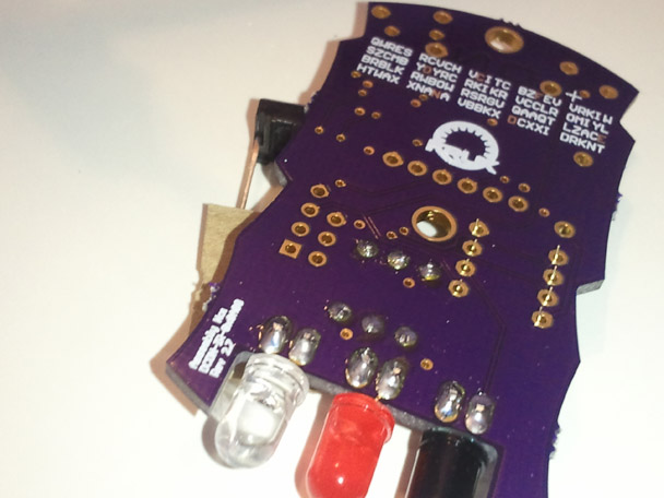
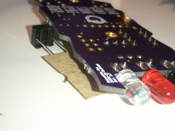
Step 9.
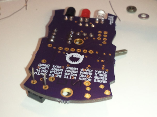
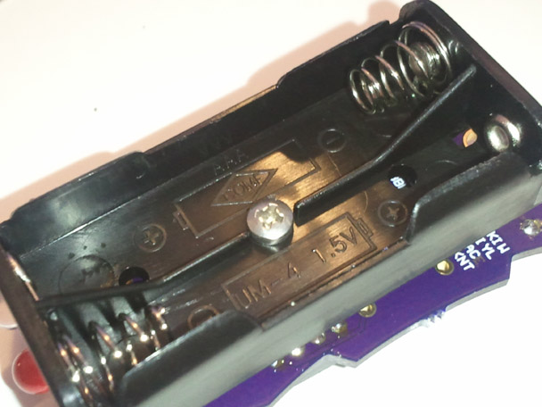
Attach battery pack. Before soldering the battery pack attach using the supplied screw, washer, and nut. The nut and washer go on the front face of the board so as to not interfere with the batteries. Do not over tighten the battery pack. It should be just tight enough that the battery pack is parallel to the PCB.
Step 10.
Solder battery pack
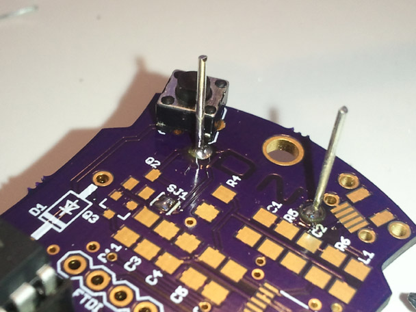
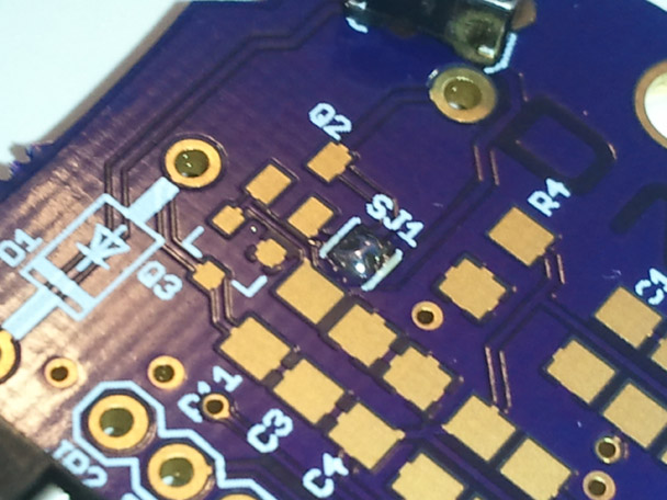
Step 11.
If you are not assembing the surface mount kit, solder the jumper SJ1. This bypasses the SMD power protection circuit.
Step 12.
Install batteries and test.
The red LED should blink when you apply power, and will blink according to which mode the board is in. Pressing the reset button cycles to the next mode. |
